
mud pump valve seat free sample

Alibaba.com offers pump valve, and a variety of different sizes to meet the needs of different customers. If it iss to the type of mud pump seat, it is possible to choose from a set of mud pump seals with alternate patterns, designs, and colors. On the other hand, the pivoted seat is the enduro, and the enduro has a wide range of sizes. If inflated mud pumps are not classified by one type or the other as a part of the body, it is important to consider the size of the seat and will be based on the type of mud pump seat. For a set of the two or less sizes, it is important to find the right type of mud pump seals on Alibaba.com, or known as " mud" seal, and all come in a variety of colors, and designs. Among the most popular mud pump valve seat choices are available based on the type of mud pump.
There are also semi-trush mud pump seats, including electric pump seats, and semi-trush mud pump seats so that airflow can be found on the surface. There are many choices of mud pump seats, including electric pump seats, and semi-trash mud pump seats.

My invention relates to valves of the character employed in mud pumps or other pumps adapted to pump fluid mixtures containing abrasive materials, and relates particularly to an improved form of such valve capable of longer periods of uninterrupted use than valves which are at present employed in pumps of this character.
Mud pump valves of the character to which my invention relates are subject to very rapid wear owing to the presence of abrasive materials, such -as fine particles of rocks, quartz, or sand contained in the drilling fluid or mud, and therefore must be replaced after comparatively short periods of use. Such valves ordinarily include a seat member consisting of an annular ring with a sealing seat near the upper end thereof and a spider structure across the lower portion thereof, and a valve element including a body of metal adapted to strike against the spider when the valve element is in lowered or relatively closed position and a sealing member on the metal body adapted to engage the sealing face of the seat member and prevent leakage of fluid through the valve when the valve is in its closed position. It is an object of my invention to provide a valve of the above character of simple construction yet being capable of giving a greater period of service than valves of complex structure.
It is an object of the invention to provide a valve having a seat member including an annular sealing face or seat and a valve closure member having a circular or annular sealing member of rubber material adapted to enter the space enclosed by the annular sealing seat or face of the seat member and to be deformed by fluid pressure so as to expand against the sealing face of the seat member.
It is a further object of the invention to provide a valve of the above character in which the cooperative parts are so formed that the sealing member preferably wipes the sealing face clean as it moves into closed position, thereby reducing to a minimum the particles of abrasive material which may rest between the sealing member and the sealing face, the result thereof being that the wear between these parts is minimized and the useful life of the valve materially extended.
It is a further object of the invention to provide a valve which may be used for abrasive subo5 stances and which may be also employed in pumps for circulating other fluids, such as crude oils.
It is a still further object of the invention to seal the valve by a sealing member on the valve body having a peripheral annular engagement surface adapted to be received within an annular inwardly faced sealing wall surface of the valve seat, whereby the engagement surface is adapted to be deformed radially outwardly for sealing engagement with the sealing wall surface, the seating movement of the valve body being limited by its engagement with a supporting surface of the seat member, and said supporting surface being at an angle to the direction of opening and closing movement of the valve appreciably greater than the angle of the sealing surface with relation to the direction of opening and closing movement of the valve. The supporting surface thus takes the blow and relieves the sealing member of excessive wear as the valve closes, and by its appreciable angle to the axis of the valve prevents radial distortion of the seat member or *swedging action such as might deform the seat or the valve body, while the smaller angle of the sealing surface with relation to the axis of the valve, insures a tight sealing engagement by radially deforming and confining the sealing member within the inwardly faced annular sealing wall surfade, rather than by merely pressing the sealing member against a cooperating surface lying at an appreciable angle to the axis of the valve.
Further objects and advantages of the invention will be made evident throughout the following part of the specification. Referring to the drawings, which are for illustrative purposes only, Fig. 1 is a partly sectioned elevational view showing a mud pump equipped with valves embodying my invention. Fig. 2 is an enlarged fragmentary cross section showing one of the valves in closed position.
Fig. 3 is an enlarged fragmentary sectional view similar to Fig. 2 showing the valve in relatively open position. Fig. 4 is a fragmentary sectional view showing an alternative manner in which clearance may be provided within the periphery of the sealing member of the valve.
Fig. 6 is a fragmentary sectional view showing a form of my invention adapted for use in other types of pumps, such as oil pumps. Fig. 7 is a section on a plane represented by the line 7-7 of Fg. 2.
In Fig. 1 I show a reciprocating pump 10 having a pumping cylinder I in which a piston 12 is reciprocated by a steam powered engine 13. The rightward portion of the pump 10 is sectioned so as to show discharge valves 14 which are connected with the opposite ends of the cylinder II so that as the piston 12 is reciprocated, fluid will be forced upwardly from the respective ends of the cylinder into an outlet chamber 15 which in mud pumps is connected through a rotary hose to the rotary drilling string.
As shown in Fig. 2, the preferred embodiment of my improved valve 14 includes a seat member 16 and a valve body or closure member IT which moves relative to the seat member 16. The seat member 16 includes an annular wall 18 and a support or spider 20 which extends across the lower portion of the annular wall 18, this spider 20 comprising a number of radial arms 21 extending inwardly from the annular wall 18 and a central hub 22 having an axial opening 23 therein.
Above the spider 20 the annular wall 18 is formed with an annular sealing surface 24. This sealing surface is shown as preferably flaring outwardly and upwardly at a comparatively steep angle; or the sealing surface may have no taper but be cylindrical as will be later described with reference to Fig. 5, it being the steep angle of the sealing surface that greatly contributes to the improved operation and wear resisting qualities of my new valve. The valve body I1 is in the form of a metal enlargement 25 having a lower abutment area which includes abutment surfaces adjacent both"the axis and the periphery of said enlargement and adapted, when the valve is closed, to engage the upper face of the hub 22 and the radial arms 21 which constitute the spider. The abutment surface of the enlargement 25 which is adjacent the periphery thereof engages the abutment formed by the arms 21 adjacent and extending inwardly from the annular wall 18, and the abutment surface of the enlargement 25 which is adjacent the axis thereof engages the abutment formed by the hub 22 adjacent the axis of the valve. The enlargement is equipped with guide means in the form of upwardly and downwardly projecting axial stems 26 and 27 of Sthe character commonly employed in mud pump valves. On the upper face of the body IT is a sealing member 30 consisting essentially of a flat disc of yieldable material, such as rubber or rubber compound, having an opening 31 therein through which the stem 26 projects, the sealing member 30 being held in place on the body 1I by a flange member 32 which is held down against the upper face of the sealing member 30 by means of a pin 33 extended through the stem 26. The sealing member 30 is of such external diameter that it will enter the space enclosed by the surface 24 as the closure member T1 moves from the open position in which it is shown in Fig. 3 to the closed position in which it is shown in Fig. 2. As the member I7 moves to closed position fluid pressure within the chamber 15 is exerted downwardly against the annular upwardly directed surface 34 of the sealing member 30 exposed around the flange 32, such pressure compressing the rubber or yieldable material of the peripheralportion of the sealing member 30 against the upper face of the body 17 and causing the periphery of the sealing member 30 to be expanded or deformed radially outwardly so as to be confined within and radially contact the surrounding annular wall surface 24. The sealing member 30 is shown with a shallow peripheral groove 35 so as to form the semblance 7 of a lip 36, but for some uses satisfactory results may be obtained where the upper face of the sealing member 30 is left flat.
A feature of the invention is to make the diameter of the sealing member 30 of such measure relative to the diameter of the sealing surface 24 that not later than when the body 17 engages the spider 20 the fluid pressure in the chamber 15 will have caused the peripheral face 37 of the sealing member to engage the sealing surface 24, with the peripheral face 37 sealing against the sealingsurface 24 when the valve is closed.
Another feature of the invention which may be employed, is to make the diameter of the sealing member 30 of such measure relative to the diameter of the sealing surface 24 that the fluid pressure in the chamber 15 will cause the peripheral face 37 of the sealing member to make wiping contact with the -surface 24 as the closure member 17 moves toward closed position. The sealing member 30 may be of such size that when the body IT, during its downward movement, reaches the position indicated by the dotted lines in Fig. 3, the fluid pressure in the chamber 15 will cause the lower edge of the peripheral face 37 of the sealing member 30 to engage the upper edge of the wall surface 24. As the closure member 14 then continues downwardly toward fully closed position, such as shown in Fig. 2, the surfaces 24 and 37 wipe across one another and remove from each other much of the collected material. It may be that fine abrasive materials will remain on the surfaces 24 and 37, but the condition of the valve after it has been in use for a considerable period of time indicates that this wiping action at least removes the larger partides of material which would prevent a sealing action between the periphery of the sealing member 30 and the wall surface 24. For illustration, as the closure member 17 moves to closed position, the lower peripheral corner 37" of the sealing member may wipe materials from the wall surface 24, and the upper annular corer 38 of the wall surface 24 may wipe materials from the face 37 of the sealing member 30, leaving these surfaces in such condition that a practical seal will, result. .For example, the seal formed is of such practical efficiency that I have been able to employ a single valve structure continuously for a period of over ninety days, replacing the sealing member but once during this period. At the time of signing this application this valve is still in use with the second rubber or sealing member 30.
Another feature of the invention is to yieldably urge the sealing member 30 into sealing engagement with wall surface 24, so that the sealing member may accommodate itself to wear of the metal parts of the valve structure without excessive wear of the resilient sealing member.
For this purpose the flange member 32 is of such restricted diameter that the enlargement 25 as well as the sealing member 30 project appreciably radially beyond the flange member. An appreciable area of the upper surface of the sealing member is thus exposed to the fluid pressure in chamber 15 for tightly seating the sealing member against wall surface 24, and in the event of the metal parts of the assembly being excessively worn so that the sealing member 30 is forced further down into the annular seat 24 before tightly closing the valve, the restricted diameter of the flange member 32 permits such flexing of the outer peripheral portion of the sealing member 30 as will readily adapt it to its new seating position, with said flexing of the outer peripheral portion of the sealing member avoiding cutting through and destruction of the sealing member.
A further feature of my new construction is that the parts are so. formed as to provide an annular space 40 within or below the peripheral edge 37" of the sealing member in which material dislodged from the surface 24 as the valve body moves into closed position may collect. As shown in Fig. 2, the space 40 is a continuous annular space formed by reducing the diameter of tAe body 17 immediately below the sealing member 30. In Fig. 4 I show a space 40a having the same purpose which is formed by chamfering the upper peripheral edge of a body 17a which closely fits the lower portion of the wall surface 24.
In Fig. 5 I show a form of my invention which is exactly the same as the valve shown in Figs. 2 and 3 with the exception that the sealing face or inwardly directed wall surface 24a is cylindrical for a greater part of its length and is slightly chamfered at the corner 38a. Corresponding to the surface 24a, the peripheral surface 37a of the sealing member 30a is cylindrical and may be of such diameter that responsive to fluid pressure, wiping engagement between the surfaces 24a and 37a will be accomplished as the closure member 17a moves into the closed position shown in Fig. 5, it being understood that upon reaching such closed position, fluid pressure against the sealing member causes radial expansion of its annular face 34a into tight sealing engagement with the surface 24a.
In Fig. 5 the wall surface 24a is shown cylindrical for a portion of its length and slightly flared at its upper end. In Figs. 2, 3, and 4, the wall surface 24 is shown comparatively steeply upwardly flared for the purpose of self-adjustment of the parts as the upper face of the support or spider wears down due to the repeated hammering of the body 17 thereagainst during the operation of the pump. Accordingly, in the preferred practice of my invention the wall surface 24 may have such a comparatively steep angle that the annular peripheral engagement surface of the sealing member is adapted to be radially expanded and confined within the annular wall surface 24, and moves relative to surface 24 in the direction of closing movement of the valve so as to permit ready dislodgement of abrasives rather than trapping the same between the surfaces 24-37; and the wall 24 may be flared at such a steep angle as to compensate for the wear between the surfaces 24 and 37 and between the bottom of the body 17 and the upper face of the support 20. As the stopping position of the body 17 moves downwardly as the result of the last named wear, the sealing member, which has worn slightly, assumes a stopping position relative to a lower portion of the wall surface 24 of slightly reduced diameter.
In Fig. 6 I show an alternative form of my valve having a seat member 16 of a form identical with the illustration thereof in Figs. 2, 3, and 4. In this form of the invention, however, the sealing member 30 is replaced by a dished or cupshaped sealing member 50 having a circular wall 51 and an upturned, slightly upwardly flared lip or wall 52 which provides an outer surface 53 adapted to enter the annular wall surface 24 and to be forced outwardly by fluid pressure against the upper and inner faces of the lip 52. The sealing member 50 may be made of leather and may be held in place on the body 17 by use of a flat metal disc 54 of a size to fit under the holddown flange 32. This alternative form of my invention isespecially designed for use in high pressure oil pumps or high pressure pumps for transferring other liquids. The same wiping action between the surfaces 24 and 53 of the members 16 and 50 may be accomplished, and the pounding effect due to the high pressure on the upper face of the movable valve part is received by the spider or support 20.
Another feature of the invention is that the supporting of the seat member which takes the blow when the valve closes, is at an appreciable angle to the direction of opening and closing movement of the valve, while the sealing engagement between surfaces 24-37 is at a slight angle to the direction of opening and closing movement. For example, as shown at Fig. 2, the surface 24 flares upwardly and radially outwardly at a steep angle, and the engagement surface 37 of the sealing member flares upwardly and radially outwardly at substantially the same steep angle; while the upper surface of- pider 20 which provides the abutment surface which takes the blow when the valve closes, is at an angle which is not nearly as steep.
Consequently the hammering blow of the closing valve is directed against the cooperating support of the seat member, at an angle which is at least a near approach to a right angle, so as to avoid swedging action or radial distortion of the seat member; and the sealing engagement at surfaces 24-37 is in a plane which is either parallel or close to parallel to the direction of movement of the valve, whereby material will readily dislodge from between the surfaces 24-37, and the sealing engagement is made by radially outwardly deforming and confirming the sealing member within the annular wall 24. The arresting abutment and the sealing engagement at different angles to the axis of the valve, with the arresting abutment at the greater angle, thus cooperate to define a construction wherein the valve is seated without undue wear of the sealing member and without distortion of either the valve seat or the valve body, and with foreign material dislodged from between the body and seat, and the sealing engagement resulting from radial expansion and confinement of the sealing member within an annular sealing wall of the valve seat.
I claim as my invention: 1. A valve of the character described, including: a seat member comprising an annular wall of short tubular form and a support consisting of an open-work structure extending across one end of said annular wall, the other end of said annular wall providing an outwardly flared, inwardly faced sealing wall surface; a valve body adapted to move to and from said support, said valve body comprising a guide means and an enlargement adapted to engage said support; and an annular sealing member on the upper face of said enlargement having an outwardly flared resilient peripheral portion providing an annular engagement surface adapted to engage said wall surface as said valve body moves into engagement with said support and being of such diameter relative to said wall surface as to engage said wall surface at a point b3fore said enlargement engages said support and to have a wiping movement relative to said wall surface as said enlargement moves from said point into engagement with said support, there being a space below said annular engagement surface to receive the wipings removed from said wall surface by said annular engagement surface, and the peripheral portion of the upper face of said sealing member being exposed to fluid pressure whereby such fluid pressure may deform the periphery of said sealing member outwardly to increase the pressure of the sealing engagement of said sealing member with said wall surface.
2. A valve of the character described, including: a seat member comprising an annular wall of short tubular form and a support consisting of an open-work structure extending across one end of said annular wall, the other end of said annular wall providing an outwardly flared, inwardly faced sealing wall surface; a valve body adapted to move to and from said support, said valve body comprising a guide means and an enlargement adapted to engage said support; and an annular sealing member on the upper face of said enlargement having an outwardly flared resilient peripheral portion providing an annular engagement surface adapted to engage said wall surface as said valve body moves into engagement with said support and being of such diameter relative to said wall surface as to engage said wall surface at a point before said enlargement engages said support and to have a wiping movement relative to said wall surface as said enlargement moves from said point into engagement with said support.
3. A valve of the character described including: a seat member comprising an annular wall and a support below the upper end of the annular wall, the upper end of the annular wall providing an outwardly flaring annular sealing surface; a valve body adapted to move to and from the support, said valve body comprising a guide means and an enlargement adapted to engage the support; and an annular sealing member on the upper face of said enlargement having a resilient peripheral portion providing an annular engagement surface adapted to engage 5o said annular sealing surface as the valve body moves into engagement with the support and being of such diameter relative to the annular sealing surface as to engage said annular sealing surface at a point before said enlargement en5. gages the support and to have wiping movement relative to the annular sealing surface as said enlargement"moves from said point into engagement with the support, there being a space below the annular engagement surface of suffi(; cient size to receive materials wiped from the annular sealing surface by the sealing member as said sealing member moves into closed position relative to the seat member.
4. A valve of the character described includ5, ing: a seat member comprising an annular wall and a support below the upper end of the annular wall, the upper end of the annular wall providing an outwardly flaring annular sealing surface; a valve body adapted to move to and fronh 7o the support; and an annular sealing member on the upper face of the body having an outwardly flared resilient peripheral portion providing an annular engagement surface adapted to engage said annular sealing surface as the valve body moves into engagement with the support and being of such diameter relative to the annular sealing surface as to engage said annular sealing surface at a point before the body engages the support and to have wiping movement relative to the annular sealing surface as the body moves from said point into" engagement with the support, the peripheral portion of the upper face of the sealing member being exposed to fluid pressure whereby such fluid pressure may deform the periphery of the sealing member to increase the pressure of the sealing engagement of the sealing member with the annular sealing surface.
5. A valve of the character described, including: a seat member comprising an annular wall and a support below the upper end of the annular wall, the upper end of the annular wall providing an outwardly flaring annular sealing surface; a valve body adapted to move to and from the support; an annular sealing member on the upper face of the body having a resilient peripheral portion providing an annular engagement surface adapted to engage said annular sealing surface as the valve body moves into engagement with the support and being of such diameter relative to the annular sealing surface as to engage said annular sealing surface at a point before the body engages the support and to have wiping movement relative to the annular sealing surface as the body moves from said point into engagement with the support; and a retaining member overlying the sealing member and of a diameter whereby the sealing member and the valve body project radially beyond the retaining member, so that the peripheral" portion of the sealing member may be flexed to accommodate it to the annular sealing surface and the upper face of said peripheral portion of the sealing member is exposed to fluid pressure whereby such fluid pressure may deform the periphery of the sealing member to increase the pressure of the sealing engagement of the sealing member with the annular sealing surface.
6. In a valve; a seat member comprising an annular wall and an abutment surface below the upper end of and in the bore defined by the annular wall, the abutment surface being adjacent the axis of the annular wall, the upper end of the annular wall providing an outwardly flaring annular sealing surface; a valve body adapted to move to and from the abutment surface parallel to the axis of the annular wall, the abutment surface being adapted for engagement by the valve body at an angle to the axis of the annular wall appreciably greater than the angle of the annular sealing surface to said axis; and an annular sealing member on the valve body having a resilient peripheral portion providing a peripheral engagement surface normally, flaring at substantially the same angle as that of the an- go nular sealing surface and of such diameter as to engage said annular sealing surface before the valve body engages the abutment surface, the peripheral portion of the sealing"member being exposed to fluid pressure for deforming its flar- g6 ing peripheral engagement surface for sealing contact with the annular sealing surface.
7. In a valve; a seat member comprising an annular wall and an abutment surface below the upper end of and in the bore defined by the annular wall, the upper end of the annular wall providing an outwardly flaring annular sealing surface; a valve body adapted to move to and from the abutment surface parallel to the axis of the annular wall, the abutment surface being adapted for engagement by the valve body at an angle to the axis of the annular wall appreciably greater than the angle of the annular sealing surface to said axis; and an annular sealing member on the valve body having a resilient peripheral portion providing a peripheral engagement surface normally flaring at substantially the same angle as that of the annular sealing surface, said peripheral portion of.the sealing member being of such diameter and exposed to fluid pressure so that its flaring peripheral engagement surface engages the annular sealing surface before the valve body engages the abutment surface, and seals against the annular sealing surface when the valve is closed.
8. In a valve; a seat member comprising an annular wall and an abutment surface below the upper end of and in the bore defined by the annular wall, the upper end of the annular wall providing an outwardly flaring annular sealing surface; a valve body adapted to move to and from the abutment surface parallel to the axis of the annular wall, the abutment surface being adapted for engagement by the valve body at an angle to the axis of the annular wall appreciably greater than the angle of the annular sealing surface to said axis; and an annular sealing member on the valve body having a resilient peripheral portion providing a peripheral engagement surface normally flaring at substantially the same angle as that of the annular sealing surface, said peripheral portion of the sealing member being of such diameter and exposed to fluid pressure so that its flaring peripheral engagement surface engages the annular sealing surface before the valve body engages the abutment surface, and seals against the annular sealing surface when the valve is closed; and there being space below said flaring peripheral engagement surface when the valve is closed, adapted to receive material dislodged from the annular sealing surface.
9. In combination; a valve body adapted to move to and from a cooperating annular valve seat parallel to the axis of the valve body; and an annular sealing member on the valve body having, a resilient peripheral portion providing a peripheral engagement surface normally flaring upwardly and outwardly, the valve body having an abutment surface adapted to engage the valve seat, said abutment surface being at an angle to the axis of the valve body appreciably greater than the angle of said flaring peripheral engagement surface to said axis, the flaring peripheral engagement, surface being of such diameter as to engage the valve seat before the abutment surface of the valve body engages the valve seat, and the peripheral portion of the sealing member being exposed to fluid pressure for deforming its flaring peripheral engagement surface for sealing contact with the valve seat.
10. In combination; a valve body adapted to move to and from a cooperating annular valve seat parallel to the axis of the valve body; and an annular sealing member on the upper face of the valve body having a resilient peripheral portion including an upstanding lip providing a peripheral engagement surface normally flaring upwardly and outwardly, the valve body having abutment surfaces adjacent both the periphery and the axis thereof adapted to engage the valve seat, said abutment surface being at angles to the axis of the valve body appreciably greater than the angle of said flaring peripheral engagement surface to said axis, the flaring peripheral engagement surface being of such diameter as to engage the valve seat by the time the abutment surfaces of the valve body engage the valve seat, and the lip of the sealing member being exposed to fluid pressure for deforming the flaring peripheral engagement surface of the sealing member for sealing contact with the Valve seat.
11. In combination; a valve body adapted to move to and from a cooperating annular valve seat parallel to the axis of the valve body; and an annular sealing member on the valve body having a resilient peripheral portion providing a peripheral engagement surface normally flaring upwardly and outwardly, the valve body having an abutment surface adjacent the periphery thereof adapted to engage the valve seat,"said abutment surface being at an angle to the axis of the valve body appreciably greater than the angle of said flaring peripheral engagement surface to said axis, the flaring peripheral engagement surface being of such diameter as to engage the valve seat by the time the abutment surface of the valve body engages the valve seat, and the peripheral portion of the sealing member being exposed to fluid pressure for deforming its flaring peripheral engagement surface for sealing contact with the valve seat.
12. In combination; a valve body adapted to move to and from a cooperating annular valve seat parallel to the axis of the valve body; and an annular sealing member on the valve body having a resilient peripheral portion providing a peripheral engagement surface normally flaring upwardly and outwardly, the valve body having an abutment surface adjacent the axis thereof adapted to engage the valve seat, said abutment surface being at an angle to the axis of the valve body appreciably greater than the angle of said flaring peripheral engagement surface to said axis, the abutment surface being rigid throughout its area, the flaring peripheral engagement surface being of such diameter as to engage the valve seat by the time the abutment surface of the valve body engages the valve seat, and the peripheral portion of the sealing member being exposed to fluid pressure for deforming its flaring peripheral engagement surface for sealing contact with the valve seat.
13. In combination; a valve body adapted to move to and from a cooperating annular valve seat parallel to the axis of the valve body; and an annular sealing member on the valve body having a resilient peripheral portion providing a peripheral engagement surface normally flaring upwardly and outwardly, the valve body having an abutment surface adapted to engage the valve seat, said abutment surface being at an angle to the axis of the valve body appreciably greater than the angle of said flaring peripheral engagement surface to said axis, the abutment surface being rigid throughout its area, the flaring peripheral engagement surface being of such diameter as to engage the valve seat by the time the abutment surface of the valve body engages the valve seat, and the peripheral portion of the sealing member being exposed to fluid pressure for deforming its flaring peripheral engagement surface for sealing contact with the valve seat.
14. In a valve; a seat member comprising an annular wall and an abutment surface below the upper end of and in the bore defined by the annular wall, the abutment surface being adjacent the axis of the annular wall, the upper end of the annular wall providing an outwardly flaring annular sealing surface; a valve body adapted to move to and from the abutment surface parallel to the axis of the annular wall, the abutment surface being" adapted for engagement by the valve body at an angle to the axis of the annular wall appreciably greater than the angle of the annular sealing surface to said axis; an annular sealing member on the upper face of the valve body having a resilient peripheral portion including an upstanding lip providing a peripheral engagement surface normally flaring at substantially the same angle as that of the annular sealing surface and of such diameter as to engage the annular sealing surface by the time the valve body engages the abutment surface; and a retaining member overlying the sealing member and of a diameter less than that of the upstanding lip whereby said lip is exposed to fluid pressure for deforming its flaring peripheral engagement surface for sealing contact with the annular sealing surface; there being space below said flaring peripheral engagement surface when the valve is closed, for reception of material dislodged from the annular sealing surface. 15. In a valve; a seat member comprising an annular wall and an abutment surface below the upper end of and in the bore defined by the annular wall, the upper end of the annular wall providing an outwardly flaring annular sealing surface; a valve body adapted to move to and from the abutment surface parallel to the axis of the annular wall, the abutment surface being adapted for engagement by the valve body at an angle to the axis of the annular wall appreciably 85 greater than the angle of the annular sealing surface to said axis; an annular sealing member on the upper face of the valve body having a resilient peripheral portion providing a peripheral engagement surface normally flaring at substantially the same angle as that.of the annular sealing surface; and a retaining member overlying the sealing member and of a diameter less than that of said peripheral portion of the sealing member, said"peripheral portion of the sealing member being of such diameter and exposed to fluid pressure so that its flaring peripheral engagement surface engages the annular sealing surface by the time the valve body engages the abutment surface, and seals against the annular sealing surface when the valve is closed; the valve body and the sealing member when moved to closed position cooperating with the seat member to define a space for reception of material dislodged from the annular sealing surface.
16. In a valve; a seat member comprising an annular wall and an abutment surface below the upper end of and in the bore defined by the annular wall, the upper end of the annular wall providing an outwardly flaring annular sealing surface; a valve body adapted to move to and from the abutment surface parallel to the axis of the annular wall, the abutment surface being adapted for engagement by the valve body at an angle to the axis of the annular wall appreciably greater than the angle of the annular sealing surface to said axis; an annular sealing member on the upper face of the valve body having a resilient peripheral portion providing a peripheral engagement surface normally flaring at substantially the same angle as that of the annular sealing surface; and a retaining member overlying the sealing member and of a diameter less than that of said peripheral portion of the sealing member, said peripheral portion of the sealing member being of such diameter and exposed to fluid pressure so that its flaring peripheral engagement surface engages the annular sealing surface by the time the valve body engages the abutment surface, and seals against the annular sealing surface when the valve is closed. 17. In combination; a valve body adapted to move to and from a cooperating annular valve seat parallel to the axis of the valve body; and an annular sealing member on the valve body having a resilient peripheral portion providing a peripheral engagement surface normally flaring upwardly and outwardly, the valve body having an abutment surface adjacent the axis thereof adapted to engage the valve seat, said abutment surface being at an angle to the axis of the valve body appreciably greater than the angle of said flaring peripheral engagement surface to said axis, the flaring peripheral engagement surface being of such diameter as to engage the valve seat before the abutment surface of the valve body engages the valve seat; and there being space below said flaring peripheral engagement surface when the valve is closed, adapted to receive material dislodged from the valve seat.

Manufacturer of proprietary mud pump fluid end assemblies. The company"s products include mud pump rod systems, a liner retention system, valve cover retention systems, discharge strainer systems, valve seat pulling jack, special mud pump pistons, an automatic self-supporting mud bucket and a washpipe system.

Gate valves, often called sluice valves, are common linear valve types often used in pipelines to start and stop liquid flow through ducting, allowing users to separate a section of pipe when required.
The fluid flow through the valve can be in either direction. These valves are often used in refineries and petrochemical plants applications where pressure is low.
However, many users do not have the necessary maintenance knowledge of the usage of gate valves and lack related guidance during assembling and installation of the valve. Minor problems spring up as a result.
Therefore in this article, we will be dishing out a complete guide to problems faced by users, how to fix them easily, handle and seat replacement guides, and other gate valve troubleshooting methods.
Before we go into how to test your valve, it is imperative to understand that valves are a crucial application in many industries, and they must function accurately by diverting the right pressure without leakages.
Testing, therefore, is performed as a gate valve maintenance procedure to assess the condition or health of an operational valve. These conditions include mechanical friction, flashing, cavitation, choked flow, erosion, and noise in valves, to name a few.
Middle-Pressure Test: In this test, the gate is opened to boost the pressure in the valve to the specified value. Then shut the gate, immediately remove the valve and look for leakage at the seals on both ends of the gate. Alternatively, directly insert the test medium into the plug on the cover, and check for the seals on both sides of the gate.
Blind Plate Test:This method also requires opening the ram to increase the test pressure of the valve to the specified value. After that, shut the gate and open the blind plate on one side to check for leakage. Turn the head and repeat the test above until it is qualified.
These tests are commonly conducted on valves with backseat elements, such as gate valves. The back seat tests follow the approved test procedure, but they often involve opening the valve with the packing gland loose or uninstalled.
The most common causes of gate valve failure are wear and the seat’s and wedge’s corrosion. The inner areas of a valve wear off over time, and corrosion can make the wedge stick in the open or closed position.
Therefore, gate valve manufacturers are careful about the safety aspects of the valves from the early design stage of the system. The failure of valves in the process control industry may lead to disastrous events that can jeopardize the safety of lives, investments, environment, and reputation.
Safety and risk management have to be important aspects of the system. Safe systems require industrial control valves communicating well with process liquid and equipment. Hence, let us explore some common problems faced with sluice and their solutions:
The leakage from the gate (sluice) valve is from the gate valve gland. This spillage results from a buildup of deposits against the seal, displacing the seal. To stop the leak, all that needs to be done are:
First, check whether the bolts joining the valve and the sluice are tight. If they are not sufficiently connected, the seal gasket ring and the surface of the flange sealing groove often result in leakage.
Also, check the contact surface of the seal ring and the flange sealing groove for sand holes, sand eyes, pitting, or impurities. These defects will be revealed at any time during the valve operation and pose serious threats to a safe operation. Hence, it is necessary that corresponding welding, repair, or clean-up is carried out.
Ensure careful operation, do not go hard when closing, do not open to the upper dead point, to the stop point should be reversed one or two turns of the handwheel so that the upper side of the threads close so that the medium to push the valve stem upward impacts. Make sure to operate carefully. Do not open and close it unduly.
Presence of defects like blisters, loose tissues, and squeezes on the valve and bonnet body. Also, when the quality of iron casting is below standard.
In the installation or maintenance of the sluice, leaking of the valve plate is the most common phenomenon and can be divided into two categories; leaking seal root and leaking sealing surface.
To solve this problem, first of all, check the accuracy of the seat and plate contact sealing surface. This sealing surface needs grinding, and if the surface precision is rough, it should be removed and re-grind.
Secondly, inspect the sealing surface for sand eye, indentation, pitting, crack, and other defects, and if any of these occurs, the valve seat should be replaced.
For valve seats that have pressure springs, the elasticity of the spring must be in conformity with the requirements. If the elasticity is weakened, the pressure spring should be renewed. Additionally, remove the valve plate and adjust it to a suitable size if its T-shaped joint is too loose and results in a slope.
In the installation process, it is easy to drop the welding check, scrap iron, and impurities. Therefore, the clutter should be cleaned before installation. If you forget to clean up or clean up thoroughly, it will cause the valve plate to close less than the expected depth, resulting in leakage. To solve this, remove and clean the valve body.
Finally, the valve seat should be installed with special tools. Also, check whether the seat is installed correctly. If the thread is fastened less than the expected depth, there would be a leak. Hence, make sure special tools are used for re-installation.
As the valve ages, it seizes as water circulates via the pump around the central heating system and accumulates iron and dirt deposits. All the deposits stick to rough areas, getting in the mechanisms and causing the moving parts to jam up.
In most cases of breakage, repair work has to be done using a curb box key. Once the water is closed, you can remove the broken valve with little trouble.
Gate valve overhauling procedures are simple and last longer when installed and maintained correctly. The overhauling procedures and installation techniques vary slightly for different end connections (e.g., flanged, victuals, rolled groove), but the other instructions remain the same.
Industrial gate valves can be installed using any method; however, it is best if they can be installed upright, especially in larger sizes, for easy hand wheel access.
Extension spindle is used to operate the gate valves below the ground. In utility holes or above-ground installations, hand wheels or electric actuators may be used.
Ensure that no vertical force from the extension spindle clamps down directly on the top of the valve stem, especially when the valve is installed in a chamber with an extension spindle above ground level.
All welding works should be completed before installation, and ensure that the flange has cooled to ambient temperature by installing the sluice valve using the suitable gasket.
Ensure there is no misalignment of the valve relating to the flange. Lack of correct pipe alignment is the most common cause of valve problems. Ensure the valve is supported where necessary to reduce the load on the piping assembly.
Install the spacing bolts and ensure no damage to the valve seat. Also, adjust the face to face of the two flanges, so there is sufficient space to slip the valve in or out for servicing.
Tighten each of the bolts differently (one at a time). This is so that the pressure is evenly applied and a seal is formed between the valve, gasket, and flanges.
Gate valve maintenance procedures may seem too much to do, but a few minutes of your attention goes a long way to keep a system running smoothly. Valve maintenance can save you time and money in the long run, and ignoring it can leave you stuck with malfunctioning machinery, tubing, or pipes that may require taking apart or even replacing.
The only items that require maintenance on the gate valve are packing and the lubrication of the stem. The packing gland may require adjustment after installation, especially if the valve has been stored for a long time.
Replace the valve gate by removing the top body (bonnet) and stem. Unscrew the gate and replace it with a new part. Install top of the body and refit it into line.
To replace a seat, use one that is as good as the original one, if not better. Hard seats are necessary for high load and temperature and dry fuel (propane or natural gas applications). Hard seats, however, are not required for light-duty passenger applications.
When the gate valve handle isn’t working properly, your pipes may leak. A straightforward repair will be needed if the handle or extension rod connecting the handle to the valve is broken.
Order a Replacement Handle: If the plastic or metal T-handle at the end of the extension rod broke off, make an order for another one online. Also, order a replacement handle from your valve’s manufacturer. Check for the manufacturer’s name printed directly on the handle or a sticker near the valve.
Attach Your New Handle:The final step to this guide is to attach the new handle and install it by turning clockwise. Ensure your grip with the pliers is not released. This is to keep the extension rod from sliding inside the valve.
Glide your new handle over the end of the rod, and turn it until the threading hooks together. And when it does, keep turning it by hand until you can no longer. Then, release the handle and the pliers to finish replacing the valve’s handle.
Being the most common valve for water supply, the gate valve represents a linear motion isolation valve with the function of stopping or allowing the flow.
Like other types of valves, the gate valve has problems that users have to deal with. However, most of these failures can be prevented by proper maintenance.
This post discusses how to test, assemble and install your gate valve, their common failures, and how to fix them, including its seat and handle replacement guide.
Dombor valve is an industrial valve manufacturer that provides high-quality valve solutions to fit market requirements and pipe specifications. We pride ourselves on creating suitable valve types in various conditions. So contact us today!

A mud pump is a reciprocating liner (piston/plunger) pump designed to circulate drilling fluid under high pressure down the drill string and back up the annulus. A mud pump is an important part of the equipment used for oil well drilling. The automatic valves of the fluid-end produce the pumping effect. The valves consist of a movable body and a reaction spring. The spring is designed in order to avoid leakage and prevent contact between the valve itself and the retaining cage. Its proper sizing depends on the operating conditions as well as the properties of the fluid. The valve seat geometry significantly contributes to ensure the tightness of the fluid-end. An aspect that should be carefully considered during the design of new geometries is the phenomenon of cavitation. Cavitation consists in the development of vapour cavities in the liquid phase. Inside the cavities the pressure is relatively low. When subjected to higher pressure, the voids implode and generate an intense shock wave that promotes the wear of the components (i.e. valve, valve seat, etc.). A deep understanding of the fluid behaviour is crucial for an effective design. Transient CFD simulations of the valve opening have been performed using a non-Newtonian fluid model able to describe the drilling muds. After a deep literature review, the Herschel–Bulkley model was selected as the most suitable for emulating the drilling mud. With the above mentioned approach, the reaction spring and valve seat were designed properly to avoid premature wear phenomena.
The positive displacement mud pump is a key component of the drilling process and its lifespan and reliability are critical to a successful operation.
The fluid end is the most easily damaged part of the mud pump. The pumping process occurs within the fluid end with valves, pistons, and liners. Because these components are high-wear items, many pumps are designed to allow quick replacement of these parts.
Due to the nature of its operation, pistons, liners, and valve assemblies will wear and are considered expendable components. There will be some corrosion and metallurgy imperfections, but the majority of pump failures can be traced back to poor maintenance, errors during the repair process, and pumping drilling fluid with excessive solids content.
A few signs include cut piston rubber, discoloration, pistons that are hard to remove, scored liners, valve and seat pitting or cracks, valve inserts severely worn, cracked, or completely missing, and even drilling fluids making their way to the power end of the pump.
The fluid end of a positive displacement triplex pump presents many opportunities for issues. The results of these issues in such a high-pressure system can mean expensive downtime on the pump itself and, possibly, the entire rig — not to mention the costly repair or replacement of the pump. To reduce severe vibration caused by the pumping process, many pumps incorporate both a suction and discharge pulsation dampener; these are connected to the suction and discharge manifolds of the fluid end. These dampeners reduce the cavitation effect on the entire pump which increases the life of everything within the pump.
Poor maintenance — such as improper valve and seat installation — is another factor. Improper cleaning when replacing a valve seat can leave sand or debris in the valve seat area; preventing the new seat from properly forming a seal with the fluid cylinder, causing a pathway for a washout to occur. It is important to pull up on a seat firmly by hand and make sure it doesn’t pop out and is properly seated. The seats must be seated well, before resuming repairs. You should never reuse a valve seat if at all possible.
The fluid end is the most easily damaged part of the mud pump. The pumping process occurs within the fluid end with valves, pistons, and liners. Because these components are high-wear items, many pumps are designed to allow quick replacement of these parts.
A washout occurs when fluid and solids enter the area behind or underneath a valve seat and erode the sealing surface. Washouts are usually caused by one of three issues: a worn or cracked valve seat, improper cleaning of the valve seat and deck which creates a poor seat seal, and excessive sand content in your drilling fluid. Worn or cracked valve seats can allow fluid to enter the area around the valve seat and seat deck, creating a wash point on the valve seat and causing it to cut into the fluid cylinder and seat deck.
Additionally, the throat (inside diameter) can begin to wash out from extended usage hours or rather quickly when the fluid solids content is excessive. When this happens it can cut all the way through the seat and into the fluid end module/seat deck. This causes excessive expense not only from a parts standpoint but also extended downtime for parts delivery and labor hours to remove and replace the fluid module. With that said, a properly operated and maintained mud recycling system is vital to not only the pump but everything the drilling fluid comes in contact with downstream.

⊙Mud pump spare parts of abroad brand:Eg. Liner, piston, valve assembly, valve seat, valve spring, valve rubber could be alternative for original with lower price.
⊙Original brand:Emsco、Gardner-Denver, National oilwell, Ideco, Brewster, Drillmec, Wirth, Ellis, Williams, OPI, Mud King, LEWCO, Halliburton, SPM, Schlumberger, Weatherford.

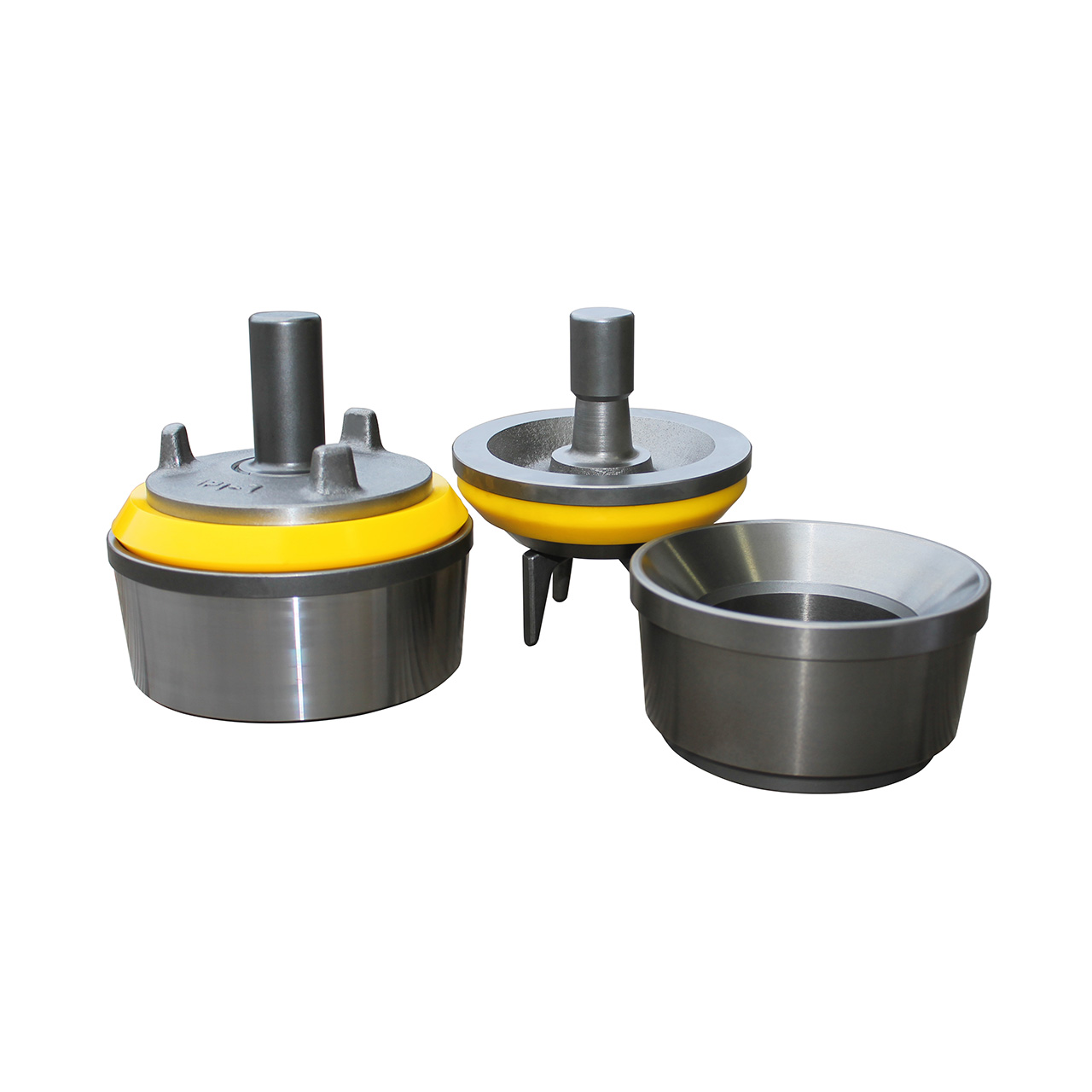
Also known as Nova Tech Valve or Roughneck Valve or High Pressure Valve. Full open Seat & wing guided Valve design features a large metal-to-metal bearing area for long life, directly casted urethane insert on valve body results in a perfect round shape that prevents premature failures of the insert. The insert is casted around the serrations, thus failure due to tears from the serrations are eliminated Most importantly the insert is not stretched over the valve during installation; there are no residual stresses left, to shorten insert life.


 8613371530291