
mud pump well drilling free sample

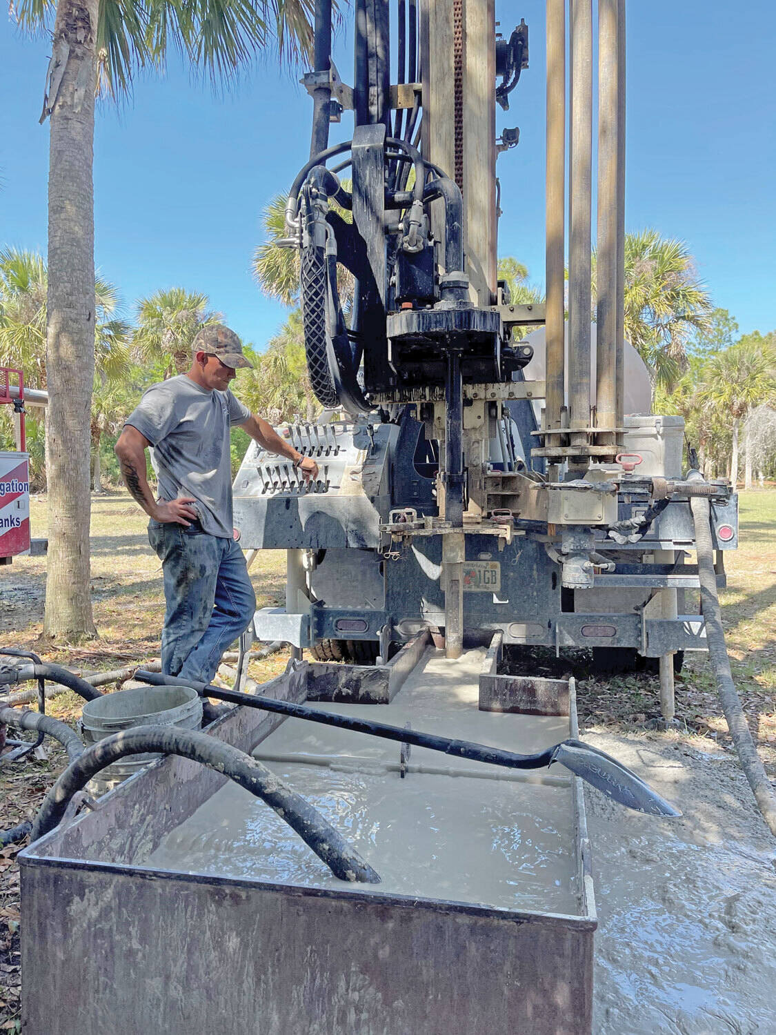
There are many different ways to drill a domestic water well. One is what we call the “mud rotary” method. Whether or not this is the desired and/or best method for drilling your well is something more fully explained in this brief summary.
One advantage of drilling with compressed air is that it can tell you when you have encountered groundwater and gives you an indication how much water the borehole is producing. When drilling with water using the mud rotary method, the driller must rely on his interpretation of the borehole cuttings and any changes he can observe in the recirculating fluid. Mud rotary drillers can also use borehole geophysical tools to interpret which zones might be productive enough for your water well.
The mud rotary well drilling method is considered a closed-loop system. That is, the mud is cleaned of its cuttings and then is recirculated back down the borehole. Referring to this drilling method as “mud” is a misnomer, but it is one that has stuck with the industry for many years and most people understand what the term actually means.
The water is carefully mixed with a product that should not be called mud because it is a highly refined and formulated clay product—bentonite. It is added, mixed, and carefully monitored throughout the well drilling process.
The purpose of using a bentonite additive to the water is to form a thin film on the walls of the borehole to seal it and prevent water losses while drilling. This film also helps support the borehole wall from sluffing or caving in because of the hydraulic pressure of the bentonite mixture pressing against it. The objective of the fluid mixture is to carry cuttings from the bottom of the borehole up to the surface, where they drop out or are filtered out of the fluid, so it can be pumped back down the borehole again.
When using the mud rotary method, the driller must have a sump, a tank, or a small pond to hold a few thousand gallons of recirculating fluid. If they can’t dig sumps or small ponds, they must have a mud processing piece of equipment that mechanically screens and removes the sands and gravels from the mixture. This device is called a “shale shaker.”
The driller does not want to pump fine sand through the pump and back down the borehole. To avoid that, the shale shaker uses vibrating screens of various sizes and desanding cones to drop the sand out of the fluid as it flows through the shaker—so that the fluid can be used again.
When the borehole has reached the desired depth and there is evidence that the formation it has penetrated will yield enough water, then it’s time to make the borehole into a well.
Before the well casing and screens are lowered into the borehole, the recirculating fluid is slowly thinned out by adding fresh water as the fluid no longer needs to support sand and gravel. The driller will typically circulate the drilling from the bottom up the borehole while adding clear water to thin down the viscosity or thickness of the fluid. Once the fluid is sufficiently thinned, the casing and screens are installed and the annular space is gravel packed.
Gravel pack installed between the borehole walls and the outside of the well casing acts like a filter to keep sand out and maintain the borehole walls over time. During gravel packing of the well, the thin layer of bentonite clay that kept the borehole wall from leaking drilling fluid water out of the recirculating system now keeps the formation water from entering the well.
This is where well development is performed to remove the thin bentonite layer or “wall cake” that was left behind. Various methods are used to remove the wall cake and develop the well to its maximum productivity.
Some drillers use compressed air to blow off the well, starting at the first screened interval and slowly working their way to the bottom—blowing off all the water standing above the drill pipe and allowing it to recover, and repeating this until the water blown from the well is free of sand and relatively clean. If after repeated cycles of airlift pumping and recovery the driller cannot find any sand in the water, it is time to install a well development pump.
Additional development of the well can be done with a development pump that may be of a higher capacity than what the final installation pump will be. Just as with cycles of airlift pumping of the well, the development pump will be cycled at different flow rates until the maximum capacity of the well can be determined. If the development pump can be operated briefly at a flow rate 50% greater than the permanent pump, the well should not pump sand.
Mud rotary well drillers for decades have found ways to make this particular system work to drill and construct domestic water wells. In some areas, it’s the ideal method to use because of the geologic formations there, while other areas of the country favor air rotary methods.
Some drilling rigs are equipped to drill using either method, so the contractor must make the decision as to which method works best in your area, for your well, and at your point in time.
To learn more about the difference between mud rotary drilling and air rotary drilling, click the video below. The video is part of our “NGWA: Industry Connected” YouTube series:
Gary Hix is a Registered Professional Geologist in Arizona, specializing in hydrogeology. He was the 2019 William A. McEllhiney Distinguished Lecturer for The Groundwater Foundation. He is a former licensed water well drilling contractor and remains actively involved in the National Ground Water Association and Arizona Water Well Association.
To learn more about Gary’s work, go to In2Wells.com. His eBooks, “Domestic Water Wells in Arizona: A Guide for Realtors and Mortgage Lenders” and “Shared Water Wells in Arizona,” are available on Amazon.

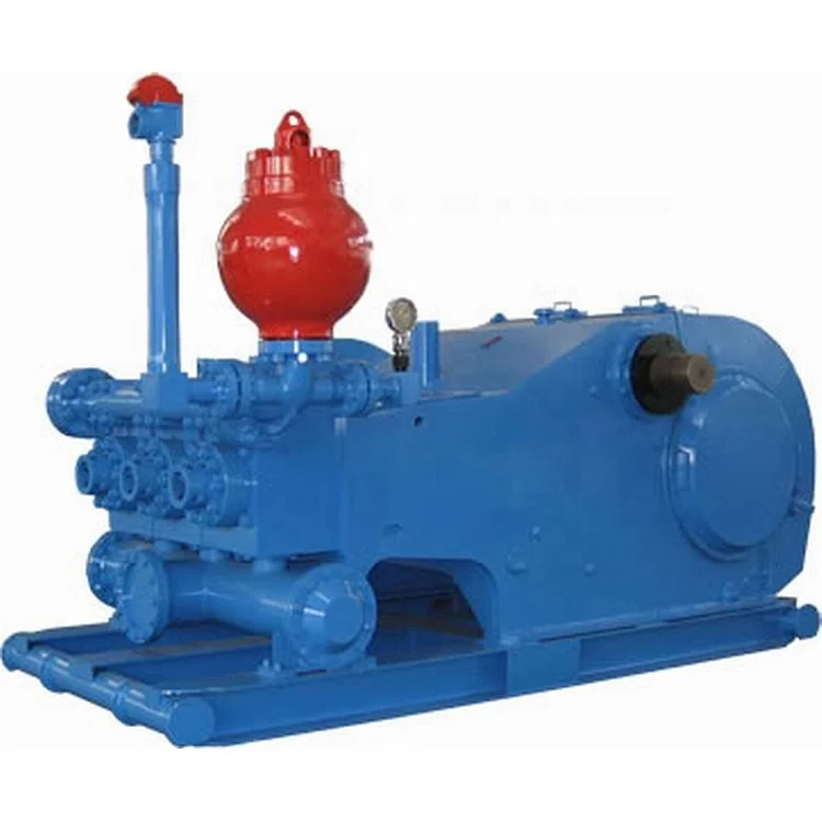
The 2,200-hp mud pump for offshore applications is a single-acting reciprocating triplex mud pump designed for high fluid flow rates, even at low operating speeds, and with a long stroke design. These features reduce the number of load reversals in critical components and increase the life of fluid end parts.
The pump’s critical components are strategically placed to make maintenance and inspection far easier and safer. The two-piece, quick-release piston rod lets you remove the piston without disturbing the liner, minimizing downtime when you’re replacing fluid parts.

OK, all y’all air drillers just thumb on over to Porky’s column or something. This is for mud drillers. On second thought, I know a lot of you air guys drill about three mud wells a year, and consider it a hassle to rig up mud. So, maybe something I say will be interesting …
The mud pump is the heart of the circulating system, and mud is the blood circulating in the hole. I’ve talked about mud before and will again, but this month, let’s talk about the pump.
Historically, more wells, of every kind, have been drilled with duplex pumps than any other kind. They are simple and strong, and were designed in the days when things were meant to last. Most water well drillers use them. The drawbacks are size and weight. A pump big enough to do the job might be too big to fit on the rig, so some guys use skid-mounted pumps. They also take a fair amount of horsepower. If you were to break down the horsepower requirements of your rig, you would find out that the pump takes more power than the rotary and hoist combined. This is not a bad thing, since it does a lot of the work drilling. While duplex pumps generally make plenty of volume, one of the limiting factors is pressure. Handling the high pressures demanded by today’s oil well drilling required a pump so big and heavy as to be impractical. Some pretty smart guys came up with the triplex pump. It will pump the same — or more — volume in a smaller package, is easy to work on and will make insane pressure when needed. Some of the modern frack outfits run pumps that will pump all day long at 15,000 psi. Scary. Talk about burning some diesel.
The places that triplex pumps have in the shallow drilling market are in coring and air drilling. The volume needs are not as great. For instance, in hard rock coring, surface returns are not always even seen, and the fluid just keeps the diamonds cool. In air drilling, a small triplex is used to inject foam or other chemicals into the air line. It’s basically a glorified car wash pump. The generic name is Bean pump, but I think this just justifies a higher price. Kinda like getting the same burger at McDonald’s versus in a casino.
One of the reasons water well drillers don’t run triplex pumps, besides not needing insane pressure, is they require a positive suction head. In other words, they will not pick up out of the pit like a duplex. They require a centrifugal charging pump to feed them, and that is just another piece of equipment to haul and maintain.
This brings me to another thought: charging. I know a lot of drillers running duplex pumps that want to improve the efficiency of their pumps. Duplexes with a negative suction head generally run at about 85 percent efficiency. The easy way to improve the efficiency is to charge them, thus assuring a 100 percent efficiency. This works great, but almost every one of them, after doing all that work and rigging up a charging pump, tells me that their pump output doubled. Being the quiet, mild mannered type that I am, I don’t say “Bull,” but it is. A duplex pump is a positive displacement pump. That means that it can deliver no more than the displacement it was designed for. You can only fill the cylinder up until it is full. It won’t take any more. The one exception to this is when you are pumping at very low pressure. Then the charging pump will over run the duplex, float the valves and produce a lot more fluid. Might as well shut off the duplex and drill with the charging pump.
Another common pump used in the water well industry is the centrifugal. You see them mostly on air rigs that don’t use mud too often. They have their place, but are a different breed of cat. They are not positive displacement. Flow is a function of speed and horsepower up to the limits of the pump. After that, they just dead-head. With large diameter drill pipe they make a lot of mud, but after the hole gets deeper, friction losses — both inside and outside the drill pipe — build up. This means that the deeper you go, the less circulation you have. This slows the whole process. Positive displacement pumps don’t do this; they pump the same per stroke regardless of pressure. It just takes more horsepower. Also, displacement calculations like bottoms-up time and cement placement are just about impossible. One way to get around the limited pressure of centrifugal pumps is to run two of them in series. I’ve seen a few of these rig-ups and they work very well for large diameter drilling. They will make almost the same pressure as a big duplex for a lot less money. They are still variable displacement, but they roll so much fluid that it doesn’t seem to matter. And run at pretty reasonable depths, too: 300 to 400 psi at 400 gpm is not uncommon with two 3 x 4 centrifugal pumps in series.
I reckon there are pumps for every type of drilling. It is just a matter of using the right one correctly. I once drilled a 42-inch hole 842 feet deep with a 5½ x 8 duplex. Talk about long bottoms-up time … but we got the casing in with less than two feet of fill on bottom! Took time, but we got-er-done.

When choosing a size and type of mud pump for your drilling project, there are several factors to consider. These would include not only cost and size of pump that best fits your drilling rig, but also the diameter, depth and hole conditions you are drilling through. I know that this sounds like a lot to consider, but if you are set up the right way before the job starts, you will thank me later.
Recommended practice is to maintain a minimum of 100 to 150 feet per minute of uphole velocity for drill cuttings. Larger diameter wells for irrigation, agriculture or municipalities may violate this rule, because it may not be economically feasible to pump this much mud for the job. Uphole velocity is determined by the flow rate of the mud system, diameter of the borehole and the diameter of the drill pipe. There are many tools, including handbooks, rule of thumb, slide rule calculators and now apps on your handheld device, to calculate velocity. It is always good to remember the time it takes to get the cuttings off the bottom of the well. If you are drilling at 200 feet, then a 100-foot-per-minute velocity means that it would take two minutes to get the cuttings out of the hole. This is always a good reminder of what you are drilling through and how long ago it was that you drilled it. Ground conditions and rock formations are ever changing as you go deeper. Wouldn’t it be nice if they all remained the same?
Centrifugal-style mud pumps are very popular in our industry due to their size and weight, as well as flow rate capacity for an affordable price. There are many models and brands out there, and most of them are very good value. How does a centrifugal mud pump work? The rotation of the impeller accelerates the fluid into the volute or diffuser chamber. The added energy from the acceleration increases the velocity and pressure of the fluid. These pumps are known to be very inefficient. This means that it takes more energy to increase the flow and pressure of the fluid when compared to a piston-style pump. However, you have a significant advantage in flow rates from a centrifugal pump versus a piston pump. If you are drilling deeper wells with heavier cuttings, you will be forced at some point to use a piston-style mud pump. They have much higher efficiencies in transferring the input energy into flow and pressure, therefore resulting in much higher pressure capabilities.
Piston-style mud pumps utilize a piston or plunger that travels back and forth in a chamber known as a cylinder. These pumps are also called “positive displacement” pumps because they literally push the fluid forward. This fluid builds up pressure and forces a spring-loaded valve to open and allow the fluid to escape into the discharge piping of the pump and then down the borehole. Since the expansion process is much smaller (almost insignificant) compared to a centrifugal pump, there is much lower energy loss. Plunger-style pumps can develop upwards of 15,000 psi for well treatments and hydraulic fracturing. Centrifugal pumps, in comparison, usually operate below 300 psi. If you are comparing most drilling pumps, centrifugal pumps operate from 60 to 125 psi and piston pumps operate around 150 to 300 psi. There are many exceptions and special applications for drilling, but these numbers should cover 80 percent of all equipment operating out there.
The restriction of putting a piston-style mud pump onto drilling rigs has always been the physical size and weight to provide adequate flow and pressure to your drilling fluid. Because of this, the industry needed a new solution to this age-old issue.
As the senior design engineer for Ingersoll-Rand’s Deephole Drilling Business Unit, I had the distinct pleasure of working with him and incorporating his Centerline Mud Pump into our drilling rig platforms.
In the late ’90s — and perhaps even earlier — Ingersoll-Rand had tried several times to develop a hydraulic-driven mud pump that would last an acceptable life- and duty-cycle for a well drilling contractor. With all of our resources and design wisdom, we were unable to solve this problem. Not only did Miller provide a solution, thus saving the size and weight of a typical gear-driven mud pump, he also provided a new offering — a mono-cylinder mud pump. This double-acting piston pump provided as much mud flow and pressure as a standard 5 X 6 duplex pump with incredible size and weight savings.
The true innovation was providing the well driller a solution for their mud pump requirements that was the right size and weight to integrate into both existing and new drilling rigs. Regardless of drill rig manufacturer and hydraulic system design, Centerline has provided a mud pump integration on hundreds of customer’s drilling rigs. Both mono-cylinder and duplex-cylinder pumps can fit nicely on the deck, across the frame or even be configured for under-deck mounting. This would not be possible with conventional mud pump designs.
The second generation design for the Centerline Mud Pump is expected later this year, and I believe it will be a true game changer for this industry. It also will open up the application to many other industries that require a heavier-duty cycle for a piston pump application.

The LS300H takes the hydraulic drill line to new depths thanks to a powerful 13-horsepower mud pump. The water well drill features the same user-friendly design and hassle-free operation as the LS200H, but with a drilling depth of up to 300 feet. Its heavy-duty welded steel frame and re-enforced table base provide added durability while the drill’s powerful hydraulics delivers pull-back and push-down forces up to 5,000 pounds. The rig’s three-way ball valve enables quick bypass mudflow when adding pipe, and the swivel base design moves the rotary aside to access the borehole.
I’ve run into several instances of insufficient suction stabilization on rigs where a “standpipe” is installed off the suction manifold. The thought behind this design was to create a gas-over-fluid column for the reciprocating pump and eliminate cavitation.
When the standpipe is installed on the suction manifold’s deadhead side, there’s little opportunity to get fluid into all the cylinders to prevent cavitation. Also, the reciprocating pump and charge pump are not isolated.
The gas over fluid internal systems has limitations too. The standpipe loses compression due to gas being consumed by the drilling fluid. In the absence of gas, the standpipe becomes virtually defunct because gravity (14.7 psi) is the only force driving the cylinders’ fluid. Also, gas is rarely replenished or charged in the standpipe.
The suction stabilizer’s compressible feature is designed to absorb the negative energies and promote smooth fluid flow. As a result, pump isolation is achieved between the charge pump and the reciprocating pump.
The isolation eliminates pump chatter, and because the reciprocating pump’s negative energies never reach the charge pump, the pump’s expendable life is extended.
Investing in suction stabilizers will ensure your pumps operate consistently and efficiently. They can also prevent most challenges related to pressure surges or pulsations in the most difficult piping environments.
Sigma Drilling Technologies’ Charge Free Suction Stabilizer is recommended for installation. If rigs have gas-charged cartridges installed in the suction stabilizers on the rig, another suggested upgrade is the Charge Free Conversion Kits.
Instead of using paper checklists when out in the field, drilling contractors and rig inspection services can generate a new inspection form from anywhere and the results are saved electronically.
Specifically designed for drilling companies and others in the oil and gas industry, the easy to use drilling rig inspections app makes it easy to log information about the drill rigs, including details about the drill rigs operators, miles logged and well numbers. The inspection form app covers everything from the mud pump areas and mud mixing area to the mud tanks and pits, making it easy to identify areas where preventative maintenance is needed. The drilling rig equipment checklist also covers health and safety issues, including the availability of PPE equipment, emergency response and preparedness processes, and other critical elements of the drilling process and drill press equipment.

The drilling operations app was designed specifically for the mud pump area in the drill rig, and covers relevant safety topics, including drilling mud level, drilling equipment safety, pipe pressure, drilling process and more.
The oil and gas rig equipment app can be customized for different drilling rig locations. Once the drilling equipment and rig floor have been inspected, users can sign off on the results electronically.
ENGINEERED FOR EFFICIENCY: with six functions along the centerline, use machine hydraulics and controls to side-shift the head, simplifying your geotech applications. Complete augering, mud rotary, SPT, Shelby tubes, hard rock cores, CPT — even direct push — without manipulating mast position or mobilizing multiple machines.
ENHANCED EASE AND SAFETY: boost geotechnical drill output and utilization with hands-free automatic drop hammer and integrated CPT head-feed rate control, including cone overload protection. Leverage small footprint to expand site access without sacrificing flow from mud pump or accessory storage. Bring new drillers up the learning curve quickly with easy controls and integrated safety features built to internationally-accepted standards.
Six functions along the 28-inch centerline head side shift simplify traditional geotechnical applications — augering, mud rotary, SPT, Shelby tubes, hard rock cores, CPT – and even direct push. Features GH63 percussion hammer 4-speed rotary head with 4,000 ft-lb, DH104 hands-free automatic drop hammer, CPT push/pull assembly, and a rod grip pull system. Head shifting speeds up drilling and minimizes the time driller spends in danger zone.
Drill mast features extend, swing, mast dump, oscillation, and fold. Mast dump provides 36.5 inches of vertical travel to allow room for a mud pan. Optional outriggers available.
Also available is a third winch with 1,100 lbs of line pull, well suited to trip additional tooling out of the hole. Equipped with the Geoprobe® exclusive quick change hook, operators can switch over to wireline coring in seconds.
All functions are at your fingertips in a well-organized, compact control panel. The systems display provides real-time systems analysis and a suite of built-in diagnostic tools. Also included are system safeguards that protect the main engine and hydraulic components when important operational parameters are compromised.
Hands-free rotary and head feed controls on the 3126GT reduce strain on driller when completing applications like mud rotary. CPT feed rate and hydraulic limit functions are standard.
The 7-inch single breakout firmly grips casing with a clamp force of up to 21,000 pounds of force. The breakout can be positioned either under the hammer or the rotary drive, as well as swung away from the machine.

A fast and efficient method of drilling, mud rotary drilling is effective in a wide range of geological formations, including sand, silt, clay, gravel, cobbles, and boulders. Not hindered by the presence of groundwater, a mud drill is also used for coring bedrock.
With the necessary torque for powerful rotation, new and seasoned operators find the Geoprobe® line of geotechnical drilling rigs and combination drilling rigs make for an effective mud drill thanks to:
With rig service shops in Pennsylvania, Kansas, and Florida, you’ll have industry-leading drill rig service support nearby for your routine maintenance or more in-depth rig remounting and refurbishment work - keeping your mud drill in the field earning dollars. Our service technicians are backed by our team of engineers to ensure solutions not bandaids to issues. And our production processes mean your mud drill is constructed consistently and tested thoroughly to ensure easier service support.
Engineered with efficiency and ease in mind, investing in a Geoprobe® mud drill simplifies your sampling while reliably ramping up production and rig utilization rates.
Our team of engineers thrives on collaborating with drillers while they continually innovate new designs for our mud drill line. Our goal is to make your job faster, safer, and easier. Partner with us and we"ll work to decrease your mud drill downtime while increasing your family time.

1.1.1 The rig is suitable for survey and prospecting, geophysical exploration, roads and buildings and other exploration and play blasthole drilling bits projects.
1.1.4 Rated drilling depth 100m, the deepest can not exceed 120m. Nominal hole diameter of 110mm, the maximum opening straight Diameter allowed to be 130mm, the final hole diameter of 75mm, drilling depth according to ground conditions.

Created specifically for drilling equipment inspectors and others in the oil and gas industry, the Oil Rig Mud Pump Inspection app allows you to easily document the status and safety of your oil rigs using just a mobile device. Quickly resolve any damage or needed maintenance with photos and GPS locations and sync to the cloud for easy access. The app is completely customizable to fit your inspection needs and works even without an internet signal.Try Template

n: a record made each day of the operations on a working drilling rig and, traditionally, phoned, faxed, emailed, or radioed in to the office of the drilling company and possibly the operator every morning.
(pronounced "tower") n: in areas where three eight-hour tours are worked, the shift of duty on a drilling rig that starts at or about daylight. Compare evening tour, morning (graveyard) tour.
(pronounced "tower") n: in areas where two 12-hour tours are worked, a period of 12 hours, usually during daylight, worked by a drilling or workover crew when equipment is being run around the clock.
n: the mass or weight of a substance per unit volume. For instance, the density of a drilling mud may be 10 pounds per gallon, 74.8 pounds/cubic foot, or 1,198.2 kilograms/cubic meter. Specific gravity, relative density, and API gravity are other units of density.
n: a large load-bearing structure, usually of bolted construction. In drilling, the standard derrick has four legs standing at the corners of the substructure and reaching to the crown block. The substructure is an assembly of heavy beams used to elevate the derrick and provide space to install blowout preventers, casingheads, and so forth.
n: the crew member who handles the upper end of the drill string as it is being hoisted out of or lowered into the hole. On a drilling rig, he or she may be responsible for the circulating machinery and the conditioning of the drilling or workover fluid.
n: a high-compression, internal-combustion engine used extensively for powering drilling rigs. In a diesel engine, air is drawn into the cylinders and compressed to very high pressures; ignition occurs as fuel is injected into the compressed and heated air. Combustion takes place within the cylinder above the piston, and expansion of the combustion products imparts power to the piston.
n: an oilwell-surveying method that determines the direction and angle of formation dip in relation to the borehole. It records data that permit computation of both the amount and direction of formation dip relative to the axis of the hole and thus provides information about the geologic structure of the formation. Also called dipmeter log or dip log.
n: 1. intentional deviation of a wellbore from the vertical. Although wellbores are normally drilled vertically, it is sometimes necessary or advantageous to drill at an angle from the vertical. Controlled directional drilling makes it possible to reach subsurface areas laterally remote from the point where the bit enters the earth.
n: in well cementing, the fluid, usually drilling mud or salt water, that is pumped into the well after the cement is pumped into it to force the cement out of the casing and into the annulus.
n: a source of natural reservoir energy in which the dissolved gas coming out of the oil expands to force the oil into the wellbore. Also called solution-gas drive. See reservoir drive mechanism.
n: 1. an abrupt change in direction in the wellbore, frequently resulting in the formation of a keyseat. 2. a sharp bend permanently put in an object such as a pipe, wire rope, or a wire rope sling.
n: a drilling tool made up in the drill string directly above the bit. It causes the bit to turn while the drill string remains fixed. It is used most often as a deflection tool in directional drilling, where it is made up between the bit and a bent sub (or, sometimes, the housing of the motor itself is bent). Two principal types of downhole motor are the positive-displacement motor and the downhole turbine motor.
adj: pertaining to packers and other tools left in the wellbore to be broken up later by the drill bit. Drillable equipment is made of cast iron, aluminum, plastic, or other soft, brittle material.
n: the employee normally in charge of a specific (tour) drilling or workover crew. The driller’s main duty is operation of the drilling and hoisting equipment, but this person may also be responsible for downhole condition of the well, operation of downhole tools, and pipe measurements.
n: an agreement made between a drilling company and an operating company to drill a well. It generally sets forth the obligation of each party, compensation, identification, method of drilling, depth to be drilled, and so on.
n: an internal-combustion engine used to power a drilling rig. These engines are used on a rotary rig and are usually fueled by diesel fuel, although liquefied petroleum gas, natural gas, and, very rarely, gasoline can also be used.
n: circulating fluid, one function of which is to lift cuttings out of the wellbore and to the surface. It also serves to cool the bit and to counteract downhole formation pressure.
n: all members in the assembly used for rotary drilling from the swivel to the bit, including the kelly, the drill pipe and tool joints, the drill collars, the stabilizers, and various specialty items. Compare drill string.
n: a method of formation testing. The basic drill stem test tool consists of a packer or packers, valves or ports that may be opened and closed from the surface, and two or more pressure-recording devices. The tool is lowered on the drill string to the zone to be tested. The packer or packers are set to isolate the zone from the drilling fluid column.
n: a type of portable service or workover rig that is self-propelled, using power from the hoisting engines. The driver"s cab and steering wheel are mounted on the same end as the mast support; thus the unit can be driven straight ahead to reach the wellhead.
n: any well that does not produce oil or gas in commercial quantities. A dry hole may flow water, gas, or even oil, but not in amounts large enough to justify production.
n: a single well that produces from two separate formations at the same time. Production from each zone is segregated by running two tubing strings with packers inside the single string of production casing, or by running one tubing string with a packer through one zone while the other is produced through the annulus. In a miniaturized dual completion, two separate casing strings are run and cemented in the same wellbore.
n: a bailing device with a release valve, usually of the disk or flapper type, used to place, or spot, material (such as cement slurry) at the bottom of the well.


 8613371530291