
bomco f 1600 mud pump price
This website is using a security service to protect itself from online attacks. The action you just performed triggered the security solution. There are several actions that could trigger this block including submitting a certain word or phrase, a SQL command or malformed data.

If you are supplying pump supplies, you can find the most favorable prices at Alibaba.com. Whether you will be working with piston type or diaphragm type systems, reciprocating or centrifugal, Alibaba.com has everything you need. You can also shop for different sizes bomco f1600 mud pump wholesale for your metering applications. If you operate a construction site, then you could need to find some concrete pump solutions that you can find at affordable rates at Alibaba.com. Visit the platform and browse through the collection of submersible and inline pump system, among other replaceable models.
A bomco f1600 mud pump comes in different makes and sizes, and you buy the tool depending on the application. The pump used by a filling station is not the one you use to fill up your tanks. There are high flow rate low pressure systems used to transfer fluids axially. On the other hand, you can go with radial ones dealing with a low flow rate and high-pressure fluid. The mixed flow pump variety combines radial and axial transfer mechanisms and works with medium flow and pressure fluids. Depending on what it will be pumping, you can then choose the bomco f1600 mud pump of choice from the collection at Alibaba.com.
Alibaba.com has been an excellent wholesale supplier of bomco f1600 mud pump for years. The supply consists of a vast number of brands to choose from, comes in different sizes, operations, and power sources. You can get a pump for residential and large commercial applications from the collection. Whether you want a water pump for your home, or run a repair and maintenance business, and need a supply of bom co f1600, mud pump, you can find the product you want from the vast collection at Alibaba.com.therther it is for refrigeration, air conditioning, transfer, or a simple car wash business, anything you want, Alibcom. it has easy to find the right youco for your00.
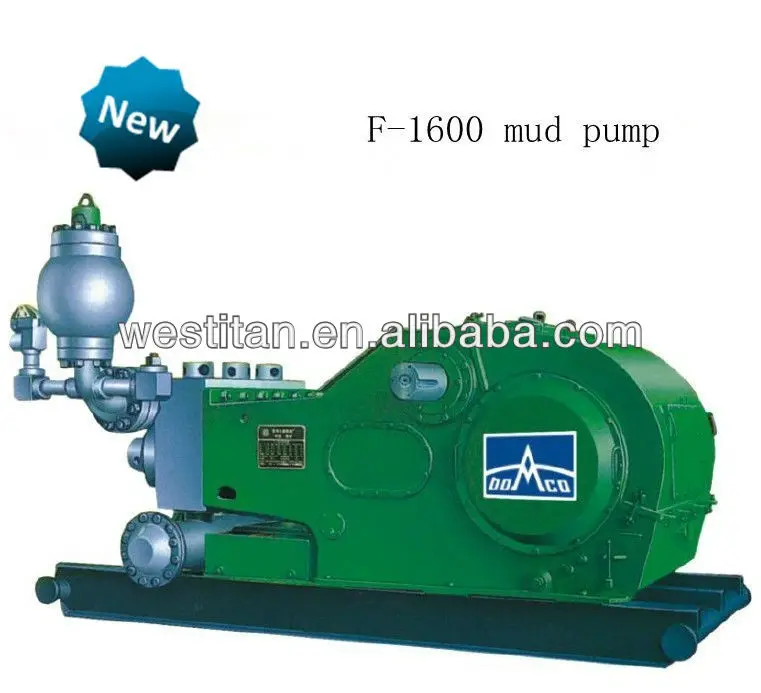
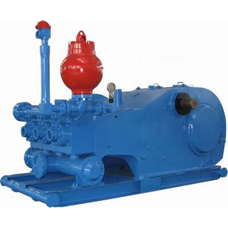
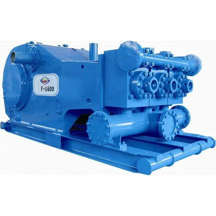
Fseries mud pumps from BOMCO is the best mud pump on the international.F-1600 mud pumps meet for high pump pressure and large displacement in oilfields.

Xi"an Kingwell Oilfield Machinery Co.,Ltd is a professional supplier for oilfield products according to the API standard. Our products have exported to USA, Canada, Australia, Egypt, India and Uae, etc with high quality and short supply and good service, our products have got good reputation home and abroad .
Equipped with latest machining facilities. Our company could meet long term production target and be governed efficiently by well-qualified and experienced Board of Directors and Engineers.
We have a team of well qualified and experienced field support personnel for Training. According to customer"s requirements, we provide operation training service for our customers who cooperated with us.
We believe in Customer delight, achieved by the supply of Quality Products & Services and Continual Improvement in our Manufacturing Processes for timely delivery at competitive prices. We work in a professional, competitive, and cost-effective manner consistent with the Customer requirement
Any interest of above products or relative parts, PLS feel free contact back, and we will offer a good price and show you our best service upon received from you.
We noticed you"re using an unsupported browser which may result in limited or no functionality for portions of our website. We recommend using Google Chrome, Mozilla Firefox, Microsoft Edge, or Safari for the best experience.
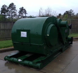
Mud Pumps - Emsco/Bomco 1600 Mud Pump, Unitized 1600 Mud Pump Powered by Two GE 752 Motors Charging Pump, Liner Flush Pump, Relief Valve, Mud Gauge, Etc. ....Call For Price More Info

standard one-and/or-two-piece configuration, with designs available for pressure of 5000psi(35.1Mpa), 7500psi(52.7Mpa), and 10000psi(70.3Mpa); discharge connections available on each side; suction connections on each side or front center.
For maximum performance and durability, our modules are made from individually forged, heat-treated alloy steel and feature an API 7 valve assembly for improved flow. Our L-shaped design features bore-seal technology for improved seal performance in higher pressures and is compatible with numerous “F-Series” drilling pumps including Honghua®, Bomco® Rongsheng®, Workforce® and other similar designs.
YINDA offers a complete line of accessories for OEM fluid end modules, CNC machining makes these accessories uniformly dimensional and interchangeable with OEM.
A: First we discuss order details, production details. Then we issue you an PI for your confirmation. You will be requested to do pr-e paid full payment or deposit before we go into production. After we get the deposit, we start to process the order. We usually need 15-25 days if we don"t have the items in stock. Before production has been finished, we will contact you for shipment details, and the balance payment. After payment has been settled, we start to prepare the shipment for you.

This website uses cookies to improve your experience while you navigate through the website. Out of these cookies, the cookies that are categorized as necessary are stored on your browser as they are as essential for the working of basic functionalities of the website. We also use third-party cookies that help us analyze and understand how you use this website. These cookies will be stored in your browser only with your consent. You also have the option to opt-out of these cookies. But opting out of some of these cookies may have an effect on your browsing experience.

The F Series mud pumps can meet the requirements of the same manufacturing technique and quality level as those of F series mud pumps of EMSCO, IDECO, GARDNER DENVOR, OILWELL etc. Now, F series mud pumps (from F-500 to F-2200) have been produced in batches and sold to many abroad oilfields. Your order for F series mud pumps is cordially welcome.
We export-orientated mud pump parts, including liners, pistons, piston inserts, valve inserts, oil seals, rod packing, fluid ends etc.. All of them meet or exceed DIN and API standards and have been exported to U.K., Germany, USA, Canada, Pakistan, Middle East, and so on.

ERUI has an independent third-party inspection team, which strictly controls the quality of products, guarantees genuine products and eliminates fakes.
ERUI has been deeply engaged in the field of oil and gas energy for many years, integrating a large number of high-quality supply channels. Our products are comprehensive and the price advantage is obvious.
The time depends on the MOQ of the order. The delivery time for parts is generally 1-3 days, and equipment is 7-30 days. In addition, contact us to get the full time of the order.

CP International, Inc. is also dedicated to providing continuing service and support services to effectively help our customers maintain and repair their equipment to full operational readiness, capacities and operational safety. CPI’s service center is located in Houston, Texas, we have a 15 acre hard surfaced yard with concrete rig up pad, 50,000 square foot shop, 15,000 square foot sandblasting and paint facility and 30,000 square foot parts warehouse.CP International, Inc.’s refurbishment, fabrication, maintenance and certification services provide extended equipment life cycle, equipment safety and efficiency giving our customers a cost effective answer to their profitability. Client experience, feedback and involvement are part of CPI"s dedication to quality and service improvements.CP International, Inc. service center is geared provides a premier level of customer service. Our service center provides equipment repair to CPI supplied products and equipment produced by other suppliers. Offering product repair, upgrade, modification, fabrication and maintenance service, our personnel have the knowledge and capability to handle any project large or small to put our customer’s equipment back in operation cost effectively with an eye always toward safety.CP International, Inc. provides a full range of repair, maintenance, and certification services to ensure that customers drilling equipment and components operate at their full capability, reliability and availability. In Stock at our Houston Facility.

This website is using a security service to protect itself from online attacks. The action you just performed triggered the security solution. There are several actions that could trigger this block including submitting a certain word or phrase, a SQL command or malformed data.
Contents PREFACE···································································································································1 1 USE OF NEW MUD PUMP········································································································2 1.1 TECHNICAL SPECIFICATION AND PERFORMANCE PARAMETER············································2 1.2 INSTALLATION OF NEW PUMP ···························································································4 1.3 Suction system requirements ···················································································8 1.4 Preparation of power end···························································································8 1.5 SPRAY PUMP ASSEMBLY ································································································10 1.6 ASSEMBLY OF FLUID END PARTS ···················································································12 1.7 Dampener Assembly ································································································17 1.8 Safety Valve ···············································································································19 2 LUBRICATION ·····················································································································19 2.1 Minimum operating speeds ·····················································································19 2.2 Controlled Flow Splash System ··············································································20 2.3 Pressure Lubrication System ··················································································21 2.4 Maintenance of Lubrication System ·······································································23 3 MAINTENANCE ··············································································································24 3.1 Power End ·················································································································24 3.2 Roller Bearings ·········································································································25 3.3 Pinion Shaft Assembly ·····························································································27 3.4 Crankshaft Assembly ·······························································································28 3.5 INSTALLING CRANKSHAFT ASSEMBLY IN FRAME ·············································30 3.6 Installation of Crosshead Guides············································································31 3.7 Installation of Crosshead ·························································································32 3.8 CHECKING CROSSHEAD ALIGNMENT ··············································································34 3.9 Fluid End Maintenance·····························································································35 3.10 WELDING AND REPAIRS ·······························································································39 3.11 REPAIR TO VALVE POT COVER BORE············································································40 3.12 CHANGE OF DAMPENER BLADDER ···············································································41 3.13 APPROXIMATE WEIGHTS OF PUMP ASSEMBLIES ···························································42
4 MAINTENANCE OF PUMP·································································································42 4.1 DAILY MAINTENANCE ···································································································42 4.2 WEEKLY MAINTENANCE ·······························································································43 4.3 MONTHLY MAINTENANCE ·····························································································44 4.4 YEARLY MAINTENANCE ································································································44 4.5 OTHERS ITEMS NEED TO BE CARED IN MAINTENANCE ····················································45
8 USE OF SPECIAL TOOLS ·········································································································49 9 LUBRICATION GUIDE ··············································································································51 10
Thanks for buying and using F-series mud pump of BOMCO. The differences of F-1300 and F-1600 mud pump are bearing of power end and gear pair, O.D. diameter, pump frame and fluid are the same. For convenience of customers, the instruction manual instruduces the two kinds of mud pump simultaneously. Operation and maintenance of F-1300/1600 mud pump is a complete set of material for customer which show numerous data and operation gists for operators, maintenance men and technicians. Because of the restraints of the paper length, the manual can’t describe every details. But if you operat the pump according to F-1300/1600 operation and maintenance manual, the pump can be assured for long operational use time and extended service life. All the specification and data are compiled according to Engineering Design, they should
F-1300/ F-1600 mud pump of BOMCO is a very important equipment of drilling rig, the function is transmiting drilling mud through to cool drill bits, clean bottom hole, break the rock, carry rock waste and balance formation pressure during drilling The design and manufacture of F-series mud pump is in compliance with API Spec 7K 《Specification for Drilling and Well Servicing Equipment》 1.1 Technical Specification and Performance Parameter 1.1.1 Technical Specification
50.42 44.97 39.83 35.01 30.50 (799) (713) (631) (555) (483) 46.54 41.51 36.77 32.32 28.15 *120 969 1300 1193 1600 (737) (658) (583) (512) (446) 42.66 38.05 33.71 29.62 25.81 110 889 1192 1094 1467 (676) (603) (534) (469) (409) 38.78 34.59 30.64 26.93 23.46 100 808 1083 994 1333 (614) (548) (485) (427) (372) 34.90 31.13 27.58 24.24 21.11 90 727 975 895 1200 (553) (493) (437) (384) (334) 0.3878 0.3459 0.3064 0.2693 0.2346 1 (6.147) (5.483) (4.857) (4.269) (3.719) Note:1. Based on 100% volumetric efficiency and 90% mechanical efficiency. 2. Recommended stroke and input power when pump running 130
Fig 1 F-1300/1600 mud pump overall dimensions 1.2 Installation of New Pump F-1300/1600 mud pump has been completely assembled and tested under pressure before being shipped from factory, the lubricating oil has been drained from power end as well. Before putting the pump into service, the measures and operations must be checked andperformed: In order to prevent personal injury during the operation of any maintenance or inspection procedures, this equipment must be shut down and not running, and all safeguards on prime movers, drives, etc, must be installed and in the safe position. The skid of BOMCO F-1300/1600 mud pump can adapt to all kinds mounted type, but 4
Figure 2 1.2.1 Land Installation In land installations, 8 pieces of shim plate (76mm×305mm) should be laid down along the length of pump skid indicated in Fig.2. The boards should be 300mm wider than the width of the pump skid beams. Wet or marshland may require a more stable foundation. 1.2.2 Permanent Installation Install the mud pump on drilling ship, structural base or construction of drilling platform, the skid should be shimed and fixed with bolts to prevent twisting or distorting of pump frame. The pump skids must sit solid on all shim points when bolts loose. If the pumps are installed on drilling ship, the skids are gerenally bolted to T-beams, the shims should be put properly according to Fig, 2 and 3 to prevent twist or distortion. All the shims should be wider the skid beam flanges and have a minimum length of 12″ (305mm).
If the power unit, transmission and pump skid are mounted integrally, the mud pump package must be installed on skid with T beam fitting with stop block rather than bolts to hold it in place. This way will allow the pump to “float” and minimize the deformation possibility of pump frame due to the deformation of ship platform or drilling platform. 1.2.3 Installation of transmission device The transmission between the mud pumps and the power source are V-belts or multistrand chain, should be installed accurately to assure maximum service life and the least shutdown time due to transmitting failures. When installing the drive sheave of sprocket, make sure all grease or rust preventative is removed from the shaft and the bore of the drive. Remove all burrs or rough spots from the shaft, key, and keyway. Fit key to the keyways in both the shaft and drive and install key into shaft keyway. Coat pinion shaft with a light coating of anti-seize compound or light oil and install the drive sheave or sprocket hub,tighten hub bolts as indicated below: When a wrench or length of pipe is used to increase leverage in tightening draw-up bolts, it is imperative to adhere to the wrench torque values given in the chart below. This adherence is important, because in mounting the hub, the tightening force on the bolts is multiplied many times by the wedging action of the tapered surface. This action compresses the hub for a snug fit on the shaft. If the bolt-tightening forces are extreme, bursting pressure is created in the hub of the mounted pulley; this pressure may cause the pulley to crack. The hub bolts should always be tightened alternately and progressively. Wrench Torque N·m 810
Note:N=0.1kgf 1.2.3.1 V-Belt Drives 1) Check sheaves groove condition Before installing, check sheave grooves for wear. Worn or rounded grooves will destroy V-belts rapidly. The sidewalls must be straight. Sheave grooves must be free of dirt, rust or other extrusions, which could damage the V-belts. 2)Check the sheave alignment 3) Adjust V-belt for proper tension Adjust the belt tension by moving the sheaves apart until all of the sag has just been
eliminated from the tight side of the belt and some of the belts on the slack side. Then increase the given center distance. For example: on 2540mm(100″) Center distance, after adjusted center distance then increase additional 13mm(1/2″). On 3180mm (150″) center distance, after adjusted center distance then increase additional 19.5mm (3/4″). Do not obtain belt tension by picking up end of pump and allowing belts to tighten under weight of pump as end is being lowered to the ground. 1.2.3.2 Chain drives 1)Installation Proper installation and maintenance of the sprocket and chain drives are essential if good service life is to be obtained. Since many factors, such as chain width, center distances, speeds, and loads must be considered when determining the allowable tolerance for sprocket alignment; no good “rule of thumb” can be applied. The chain alignment must simply be held as nearly perfect as possible. A more precise alignment can be made by stretching two steel wires (piano wire) along one face of the two sprockets, one above and one below the centerline, and moving one of the sprockets until the wires touch at four points. This will determine that the centerlines of the drives are parallel and the faces of the sprockets are square. 2) Drive chain lubrication The pump drive chain lubrication system on the majority of BS pumps is an independent system having its own oil pump, reservoir, and drive. Fill chain case to the indicated lever. SAE number of lubrication oil is refer to 《Choose of BOMCO product lubrication oil》 For temperature below -18℃ ( 0°F ) , consult a reputable lubrication dealer for recommendations. Refer to general lubrication bulletin for approved lubricants and additional specifications Since this is an independent system, it will require the same maintenance or service attention employed on any other piece of machinery, including: ——Daily check of oil lever. ——Daily check on condition of oil. ——Frequent check on oil pressure. (5~15PSI,that is 0.035~0.103MPa) ——Volume of oil being applied to chain. ——Condition of nozzles in spray tube. ——Condition of oil pump drive( V-belts or chain) Note: ① Oil pressure may be adjusted with pressure relief adjusting screw on rear of 7
the pump housing. ②Pressure drops or increase may also indicate suction and discharge filter screens need cleaning. 1.3 Suction system requirements Individual installation conditions will dictate the design of suction system. The suction of F-series pumps must have a positive head(pressure) for satisfactory performance. The optimum suction manifold pressure is 0.14 ~ 0.21MPa(20 ~ 30psi) for maximum volumetric is efficiency and expendable parts life. This head pressure is best supplied by a 6×8 centrifugal pump with 45Kw、1450rpm electric motor. This type of drive requires a device to automatically start and stop the centrifugal pump motor simultaneously with the triplex pump. On DC electric powered rigs a signal can usually be supplied from the DC control panel to energize a magnetic starter. The charging pump can also be belt driven from the triplex pinion shaft. The suction lines should be piped with valve arrangements so the charging pump can be by-passed so operation can be contined in event if charging pump failure or for maintenance. Operation without a charging pump can be improved by replacing the suction valve springs with a weaker spring. Suction desurgers are a very effective aid for complete filling of the liners and dampening pulsations in the suction line which results in a smoother flow in the discharge line. Caution: Do not pipe the return line from the shear relief valve back into the suction system as a relief valve operation will cause a sudden pressure rise in the system vastly greater than the system pressure ratings, resulting in damage to manifold,suction desurger and centrifugal pump. 1.4 Preparation of power end F-series pumps have been completely assembled and test operated before being shipped to the field. Unless otherwise instructed, the lubrication is drained from the power end, and the expendables are removed from the fluid end
Before operating the pump, the following must be performed or checked. 1.4.1 Power end lubrication Before installing lubricant, open inspection door in cover and check oil reservoir for possible accumulation of condensation, etc, and drain and flush by removing the pipe plugs on each side of the pump. Refer Item 2.Fig.7. Add the proper type and quantity of
lubrication in the power end. Refer to lubrication plate on pump frame for type and quantity required. Recheck oil level after pump has operated for a period of 15 minutes. Shut pump down and allow approximately five minutes for the oil level to equalize, Check at oil level gauge, Item 1, Fig 7.It is usually necessary for 3 gallons (10L) of oil to be added due to a certain amount being retained in the crosshead area and frame cavities. 1.4.2 Installation of Crosshead Extension Rods and Diaphragm Stuffing Box
Fig. 4 (1) diaphragm stuffing box and mud apron (2) Bolt (3) Shim (5) spring (6) double-lip oil seal (7)oil seal ring (8)O-ring (9) Locking spring (10)bolt (11)bolt
With reference to Figure 4, remove the diaphragm stuffing box (1) and rotate pump so that crosshead is at the front of the stroke, thoroughly clean the front of the crosshead and the face of the crosshead extension rod. Insert alignment boss on crosshead extension rod into the crosshead bore and tighten the retainer bolts (2) to the following torque, 350~370ft.lbs (475~500N.m), at last tightened with iron wire. Thoroughly clean mud apron and the face of frame, on the “A” place Fig. 4 is with the shim ③and tighten bolt ⑩to the following torque, 90~120ft.lbs(120~160N.m) Throughly clean bore and face of diaphragm stuffing box plate. Clean OD and flange of diaphragm stuffing box. Coat OD of diaphragm stuffing box with light oil and installO-ring seal (4), insert diaphragm stuffing box in plate bore and tighten capscrews to the following torque: 16~24N·m(12~18ft. lbs). The diaphragm stuffing box packing assembly consists of two double lip oil seal (6), an 9
oil seal ring (7), an O-ring (12) O-ring (8) and a lock spring (9). Install the assembly as follows: A: 1) Remove pressure spring ⑤ from double lip oil seal ⑥ and place seal in the outer position on the crosshead extension rod, with lip toward power end. Replace the pressure spring ⑤ in the seal lip and slide the seal into position in the stuffing box. 2) Install the O-ring 12 ○ into Oil seal ring ⑦. Insert O-ring 12 ○ and Oil seal ring ⑦ over rod and slide it into stuffing box bore. 3) Install the O-ring ⑧ in groove in stuffing box bore. 4) Install the double lip oil seal on left and right side of Figure 4 according to step 1). Caution: The double lip oil seal can be used in the inner of power end, position to replace the single lip seal, But Do Not use the single lip seal in the oyter position. 5) Install the locking spring ⑨. B: 1) Remove stuffing box ① from pump frame. Install double lip oil seal ⑥, O-ring 12, ○ O-ring 8 in stuffing box ①, then install O-ring ④ on cylndrical surface of stuffing box ①. Install guiding sleeve(tools) in front of extension rod as Figure 4, Coat extension rod and outer surface of guiding sleeve with light oil. Install stuffing box assembly on extension rod through guiding sleeve and push it to the right position, install it on mud apron with spring washer and bolt 11. ○ Note: Caution must be exercised to assure the pressure spring ⑤ doesn’t slip out of the groove in the oil seal lip, as severe scoring of crosshead extension rod can occur. Coat extension rod with light oil to facilitate installation of stuffing box assembly. 1.5 Spray Pump Assembly Spray pump assembly consists of spray pump, water tank and spray nozzle etc. it is used for flushing and cooling piston and linear during pump operated. Proper attention must be paid at all times to assure adequate cooling fluid is being applied to the piston and liner assembly. Stoppage of the cooling fluid will result in almost instant failure of the piston rubbers and possibly extensive damage to the liner bore. Stationary spray type have been used on F-series pumps Ref. Fig 5.It consists of a fixture (1), a steel pipe (2) and a spray nozzle (3), it make cooling fluid spray to piston and linear. Adjust cooling water supply to the manifold and inspect spray nozzle
to the manifold on the frame. Adjust regulating valve (Item 4 Fig .7) to apply as much water as possible to the liners without splashing back on the crosshead extension rods and diaphragm stuffing box plate. If water is allowed to splash on the crosshead extension rods, some of the water will work back into the power end to contaminate the lubrication oil. The cooling fluid is returned from the crosshead extension rod compartment to the setting chamber, and as the fluid overflows through the filter screen between the two sections of the tank, the solids are allowed to settle out. The filter screen will catch much of the foreign material floating in the fluid. With reference to Fig .6. Check condition of the cooling fluid at frequent intervals and CLEAN and FLUSH reservoir as required and replace the cooling fluid. Increasing Sand grain in Contaminated fluid will cause premature liner and piston wears
1.6 Assembly of Fluid End Parts A cross-section through the fluid end for F-1300/1600 is shown in Fig, 8. With reference to Fig 8, clean and assemble the fluid end parts in the following manner
tank Note: All of the parts in this fluid end assembly are designed with metal to metal seating to alleviate friction wear from breathing action encountered in modern high pressure pump operation. For this reason it is essential that all parts be clean and free of rust, nicks and burrs before being assembled.
(1)Wear plate seal (2)Wear plate (3)linear flange (4)liner sealing ring (5)linear lock (6) Liner (7) liner locking ring (8)piston rod (9) piston (10) piston sealing (11) nut (12) Allocation disc (13) valve rod guider (14) plug board (15) cylinder head sealing ring(16) Cylinder head plug(17)-cylinder head (18) valve cover sealing ring (19)-mud apron(20) Valve cover 1.6.1 Valves and Seats Remove all three discharge valve pot covers (20), and the three cylinder heads (17) and plugs (16) seen in figure 8, and thoroughly clean all machined surfaces in the fluid end with a good cleaning solvent. Note: It’s forbidden to coat grease or oil on exterior conical surface of valve seat and interior conical surface of valve seat bore. Make sure all valve seat bores are VERY CLEAN AND DRY (free of dirt, grease, anti-rust compound, etc). Thoroughly clean and dry the valve seats and installs suction and discharge valve seats into the valve pot bores. Drive seats firmly into place with a bar and hammer to ensure contact closely. Install valves and springs and the other parts.
1.6.2 Liners Installs wear plate seal (1) in counter bore of fluid end (see Fig. 8). Slide wear plate (2) over studs until it seats against fluid end. Install liner flange (3) over studs with the starting thread at the 5 o’clock position and tighten bolts to 470~510ft.lbs (640~690N.m) torque. Note: Placing the starting thread at 5 o’clock position makes engaging the liner lock threads much easier. Place liner seal (4) in counter bore of wear plate (2). Apply thin coat of grease to ID of liner lock (5) and slide over rear of liner (6). Install two-piece liner lock ring (7) in liner groove and O-ring to hold them in position. Slide liner-handling tool over liner up against liner lock ring and tighten setscrew to secure it in place. Hoist liner assembly into position with jib hoist (for lifting liner, the maxmum hoisting weight is 500KG). Apply liberal coat of grease to liner lock threads. Align the starting thread of the liner lock (5) to the 7 o’clock position and insert the liner into the liner thread ring (3) screw liner lock in until liner seats in position. Tighten with sledgehammer on hammer lugs. 1.6.3 Piston rod Clean piston (9) and piston rod (8), making sure they are free of nicks and burrs. Install “O” ring seal (10) in groove in piston head. Slide piston head (9) on rod while observing that O-ring does not fall out of groove. Tighten piston rod nut (11) to 1625~2165 N.m (1200~1600ft.lbs.) Coating grease with. Liner I.D. and piston O.D .Check ends of piston rod and extension rod to be sure they are clean and free of burrs. Insert piston rod into liner through cylinder head opening holding piston rod centered at the rear of the liner. Drive the piston into the liner with a driving tool or a piece of hardwood and sledgehammer. Use caution as the piston rod approaches the crosshead extension rod that the dowel on the end of the piston rod is not damaged. The piston rod must be supported and the dowel guided into the pilot bore. 1.6.4 Piston rod clamps The piston rod clamps are machined as one piece and then sawed in half. The two pieces are with matching numbers on each half and connected by chain. The two pieces with the same matching numbers should always be kept together as a set. Install the clamp around the rod end flanges. Tighten bolt to the following torque values: 330N.m (245ft.ls). Before the clamps are installed, mud apron (19) should be installed on the end of crosshead rod. 14
When rods and rod clamp are new a gap in excess of 5.5mm could be present between the two halves of the clamp, this is satisfactory provided the faces of the rods are seating metal to metal. As wear occurs, the halves will pull closer together. Clamping action will be lost when a gap no longer exists. At this time clamps must be replaced. Install splash plate on rear of liner. 1.6.5 Lower valve Guide and Cylinder Head Insert the lower valve guide (13) through the alignment ring and position the guide over the valve stem. Start the lock plate (14) and draw it down, compressing the valve spring and seating the valve guide in the tapered slot. Insert allocation disc (12) into pump head hole and Install head seal (15) on cylinder head plug (16). Coating seal ring and O.D. of cylinder head plug with light oil. Push the cylinder head into open side of fluid end. Coat the light oil on threads of cylinder head. Screw the cylinder head (17) in against the plug (16). Tighten cylinder head with wrench and sledge hammer provided with pump together. Fluid leakage through the drain hole will indicate a defective seal or loose cylinder head. Should on time replace seal or tighten cylinder head. DO NOT plug weep hole as this can result in severe damage to cylinder head threads, thread rings, etc, in event of a liner seal failure. 1.6.6 Valve cover Install valve cover seal (18) into bore, and after liberal application of grease or tool joint compound to the gasket and thread area, tighten the valve covers into place, using a sledge hammer and bar 1.6.7
API 5"(127mm)5000psi flange connection is provided on the discharge manifold and flange on discharge side. Remove flange and protect gasket area before welding (customer"s option) to the discharge piping. Tighten discharge flange connection bolts to 1625-2165 N.m (1200~1600ft.lbs.)Torque. To insure uniform make-up of the ring joint connection, tighten flange bolt nuts in a cross-criss order. If a blind flange is installed on the opposite end of the discharge manifold, check flange bolts and tighten to same specification as noted above 1.6.8 Suction Manifold Flange Three suction flange on manifold which have a standard thread connection 12" (305mm)and lay down according to rig yard arrangement. One flange is connected to suction manifold, one is connected to Suction desurgers, one flange is plugged by blind flange. An O-ring seal seals off the connection. Thoroughly clean O-ring groove and face of flanges before making up connection. Tighten flange bolts to 360~490N.m
1.6.9 Installation of wear plate Before installation, please check if the overflow channel of fluid stud is blocking and clean it thoroughly. Place the wear plate and liner flange with “O” mark at upward, overflow hole at lower side for easy watch. 1.6.10 Accessary Manifold An accessory manifold Fig .9.is available for installation on the discharge manifold opposite the discharge end, The manifold will accommodate a KB-75 pulsation dampener (1),a shear relief valve (3)and a pressure gauge (2).
Fig. 9 Pulsation dampener (2) pressure gauge (3) shear relief valve (4) seal ring (5) flange bolt (6) Discharge spool (7)-gasket ring (8)nut (9)seal ring An accessory manifold connect with discharge manifold by flange. Before assembly thoroughly clean ring joint groove, install ring (4) and tighten the flange bolts (5) to 1625-2165N.m(1200-1600ft. lbs)torque. To assure uniform make-up of the ring joint connection, tighten the nuts in a criss-cross order The shear relief valve (3) is installed on the discharge manifold for the purpose of protecting the pump from excessively high-pressure overloads. The relief valve must be installed so that is will be directly exposed to the mud. DO NOT PUT ANY TYPE OF SHUT OFF VALAE between the relief valve and the manifold. Pipe the discharge side of the relief valve directly into the mud pit with as few turns in the line as possible. If the turn must be made, the elbow should be over120º. IT IS NOT RECOMMENDED for the discharge side of the relief valve to be piped into the suction line of the pump. The mounting for KB-75 pulsation dampener (1) is a flange with R-39 ring gasket. Before installing dampener, thoroughly clean ring groove and ring, and after setting dampener into place, tighten the nut (8)to 950-1265N·m (700-935ft. lbs) torque. to insure uniform make-up, tighten nuts in a criss-cross order. At each side of discharge crossis flange with seal ring ⑨R-27. Before installation, 16
thoroughly clean seal ring and groove, the torque of connecting bolt and nut is 495-660N·m(365-490 ft. lbs) in a criss-cross order . Precharge dampener before starting up pump. Dampener should be charged with nitrogen or air. (with reference this instruction manual“dampener”)
(1) Gasket ring (2) bottom blug (3) bladder (4) shell assembly (5) cover (6) tee joint (7) Joint(8)guard of pressure gauge (9) exhaust valve (10) pressure gauge (11) stop valve
1.7 Dampener Assembly Proper installation and usage of dampener can availably reduce the pressure fluctuation of discharge system therefore obtaining more smooth fluid. For the sake of acquiring long life span of dampener, usually make pressure of pump and Precharge pressure of bladder to keep the suggestion proportion. (Precharge pressure should not be more than 2/3 of the pump discharge pressure, or a maximum of 4.5Mpa.) 1.7.1
The drawing of KB-75 pulsation dampener is Figure 10, The lifting lug installed on the shield of pressure gauge ○ 8 is used for lifting dampener assembly. Before assembly thoroughly clean gasket ring ○ 1 and groove of mating flange and coat with grease.
criss-cross order. 1.7.2 Gas charging A set of gas charging device is attendant when equipment leave factory(gas charging hose assembly of dampener)please operate as following procedure: (See Fig. 11) 1. Remove guard of pressure gauge of dampener, rotate exhaust valve cover about 1/4-1/2 turn to release the air pressure existed in pressure gauge area, then remove the exhaust valve cover. 2. Connect hose to the nitrogen cylinder switch and charge valve of dampener. 3.Open the charge valve of dampener. 4. Slowly open the nitrogen cylinder valve, use this valve to adjust incoming gas of dampener. 5. When the pressure gauge of dampener indicates pressure required then shut the nitrogen cylinder valve. 6. Shut the charge valve of dampener. 7.Remove hose, cover the guard of pressure gauge, and then install the exhaust valve. In order to obtain the best results, Precharge pressure should be no more than 2/3 of the pump discharge pressure, or a maximum of 4.5 Mpa. (650psi)
Warning: 1. Only charge with compressed nitrogen or air. Do not charge with inflammable and explosive gas such as oxygen and hydrogen etc. 2. When do maintenance to the dampener, insure the dampener discharge all the air. Do not check the pressure by pressure gauge only as low pressure which can’t be indicated by it may cause an accident.
Fig. 12 (1)Connector (2)Retainer Ring (3)Piston Assy. (4)Valve Body (5Piston Rod (6) cushion (7)Pin (8)Lock Spring (9)Safety Cap (10)Shear plate (11)Shear Pin (12)Warning Plate (13) Pin (14) Retainer Ring (15)Name Plate (16)Cotter Pin (17)Nut (18)Cap screw (19)Bolt (20)Nut(21)Cap screw JA-3shear pin safety valve drawing refers to Fig 12, When the pump pressure exceeds the rated pressure, the force acted on piston ○ 3 jacks-up the shear plate 10and ○ break down the shear pin, finally the mud flow is discharged rapidly. Change the position of shear pin can adjust the release pressure of JA-3 safety valve. The operation is simple and reliable Each work pressure is marked on the shear plate. When adjust the pressure, just insert the shear pin in the relevant hole according to the given pressure. Note: Only one shear pin can be inserted in the shear plate! Pressure must be changed if the liner size changed.(Refer to Section 1.1.2 function parameter). Wire, welding rod or other material are strictly forbidden, otherwise the valve pressure will be affected and may cause an acc a reverse accident. 2
Proper lubrication of the moving parts in any piece of machinery is the most important single factor affecting its ultimate life. To obtain maximum trouble-free service life from the power end, it is necessary to perform routine maintenance care and inspections to insure the proper amount of clean lubricant is being provided. 2.1 Minimum operating speeds The F-Series pumps utilizethe controlled flow oil bath splash and pressure system to 19
lubricate the entire power end. The type of pressure system provided in each individual pump will govern the minimum SPM at which the pump can be operated. As shown in Fig. 13, F-1300/1600 mud pump can be operated at 25 SPM. Provided(at a pressure of 0.035Mpa).
Fig. 13 Note: The pressure lubricating system can be provided with an externally mounted oil pump driven through V-belts or internally mounted oil pump driven from the main gear. When an internally mounted oil pump is used, the direction of rotation of the pinion shaft must be as shown in Fig. 13. 2.2 Controlled Flow Splash System The controlled flow splash lubrication system is the same for all F-Series pumps, regardless of the type of oil pump drive provided for the pressure system. In the controlled flow splash system, the main gear picks oil up from the reservoir, and when the teeth mesh with the pinion, the oil is displaced into various troughs and compartments in the frame. With reference to Figure 15, the oil thrown into oil trough (7) is directed through the oil tube (8) to the two pinion bearings Oil passage from the of the crosshead guide compartment to the crosshead bearing is shown in Figure 14, Oil accumulates in the compartment over the crossheads. The oil runs through the nipple (1) into the crosshead retainer to the oil passages (5) and on to the crosshead pin bearing. As noted, the duplicate set of oil passages (5) in the crosshead pin permits the crosshead pins to be rotated without having to give attention to hole alignment. This permits the installation of crosshead pins from either direction.
2.3 Pressure Lubrication System The pressure lubrication system, incorporating the oil pump for the F-series pumps, is shown in Figure 15: In this system, filtered oil is supplied to the pump through the suction filter (1) and is discharged from the pump into the manifold block (2) and nozzle (3A). Oil is distributed to the main bearing oil line (4) and the crosshead compartment manifold block (4A) located above the crosshead compartment. The crosshead compartment manifold block (4A) distributes oil to the crosshead, crosshead bearings and extension rods. A pressure gauge (5) is mounted on the back wall of the frame to show oil pressure being maintained in the manifold block. The oil pressure will, of course, vary with the speed of the main pump, however if a sudden pressure drop or increase occurs, refer to the section on maintenance of lubrication system for possible cause. A pressure relief valve (6) is mounted to the manifold block (2) to keep excess pressure from damaging oil pump and drive. The relief valve work pressure should be 0.27Mpa (40 PSI). When installing the internally mounted oil pump(item 9,Fig 15), position pump so that the back face of the drive gear is flush and parallel with the edge of the main gear, and
(1) Filter (2) manifold block (3) oil line (3A) spray nozzle (4) main bearing oil line (4A) Manifold block (5) pressure gauge (6) relief valve (7) oil trough (8) oil tube (9) Lubrication pump
A typical layout for the pinion shaft driven oil pump is shown in Fig. 16. The oil pump (1) is piped into the oil system through the suction and pressure connections on the bottom inside wall of the power frame. Do not adjust V-belt drive (2) too tight. Over tightening can cause premature failure of the pump. To prevent possible injury, always install guard (3) over V-belts before putting pump into service.
2.4 Maintenance of Lubrication System Adequate lubrication of the moving parts is, as stated, the most important single factor affecting the ultimate service life of the pump, care and maintenance of the system is the sole responsibility of the operator or crew to which it has been assigned, and the extent to which this is applied will determine the amount of trouble – free service life that will be obtained. 2.4.1 Lubrication specifications The lubricant recommendations is shown on the nameplate on the side of the pump, also can refer to 《BOMCO lubrication oil selected guidebook》. All these materials are the result of extensive long-term field tests and can validate to wear away (include gear, bearing and guild cross head). Substitutions should be made only in extreme emergencies. 2.4.2 Oil reservoir capacity: Oil reservoir capacity: 379L (100 U.S. Gallons) 2.4.3 Routine check Once each tour, check and maintain oil lever at full mark on the bayonet gauge. Pump must be shut down and allowed to stand idle for approximately five minute-to allow oil lever to equalize. Once each six month, or more often if oil becomes contaminated with abrasive particles or corrosive compounds, drain and flush the oil reservoir and pour new lubricant. Oil drains are located on eighter side of the pump frame. During the flushing procedure, thoroughly clean the oil troughs and the compartment in top of the crosshead guide. Also clean or replace the filter element in the air breather cap and clean suction screen. Remove covers from settling chamber and purge out contaminants before adding new oil. Routine inspection on condition of oil should be made as condensation of moisture in the air, instrusion of mud, water or dirt, can necessitate a more frequent oil change. A settling chamber is located in the forward area of the power end floor, The contamination in the oil splashed into this area should be drained from clean out covers. Once each month, remove clean out covers on both sides of pump to drain contaminated oil from settling chamber. Approximately 15-gallons of oil will be lost; replenish the main reservoir to compensate for amount drained out. Once each week, remove one of the lower 1/2” capscrews that secure the clean out cover to the frame to drain off water condensate.
Once each tour, check oil lever in main reservoir. Maintain at full mark on dipstick to the manifold block. If loss of pressure occurs, check for: —— Clogged suction screen —— low oil lever —— slipping V-belt drive —— Broken or loose connections —— Damaged or worn oil pump —— Defective relief valve For an abnormal increase in oil pressure, check for: —— Plugged oil lines —— Contamination causing oil to be viscous —— Relief valve inoperative —— Defective gauge —— Other conditions 3
3.1 Power End Routine inspection of the power end is the most important form of preventive maintenance and will result in considerable savings by detecting and major trouble that might be developing and allowing the necessary repaires to be made on a planned or normal rig-down time. 3.1.1 Check tightness of the main bearing bolts Torque of main bearing blots:
assembly section for bolt torque requirements.) 3.1.3 Oil Lines Check all oil lines to insure they are intact and free of obstructions. Check the suction hose of the gear pump to insure it is not damaged and staved. 3.1.4 Suctiong Filter Check condition of suction filter.Clean and repace as necessary. 3.1.5 Main Bearing Cover Remove the main bearing cover and check the tightness of the main bearing 24
bolts.condition of the bearing rollers, etc. Clean and remove any sludge of foreign substance that might have accumulated at the bottom o f the bearing area. 3.1.6 Main gear and pinion peeth Inspect the condition of the main gear teeth and pinion teeth for any indications of abnormal wear. During the initial break-in period,there will be some pitting on the face of the gear teeth .This is referred to as “initial pitting” and is not harmful to the life of the gear.However, if the routine inspection indicates the degree of the pitting
increase ,immediately contact the manufacturer for a thorough inspection of the gear. 3.1.7 Crosshead Pin Bolts and Crosshead Guides Remove cover and check condition of the crosshead pin bolts and safety wires(Remove the back cover when check the center crosshead pin blots, meantime locate the eccentric strap at the back dead position).Tighten crosshead bolts 24×70(Fig 14 item 3),torque is 225~240N·m (165~175ft. lbs) DO NOT EXCEED THE ABOVE VALUES, USE TORQUE WRENCH. If the crosshead or guide shows abnormal wear or scoring, replace immediately as the metal particles can cause damage to the bearings etc.Excess wear can also cause rapid wear to the piston and liners. 3.1.8 Lubrication and Reservoir Check condition of the oil and cleanliness of the oil reservoir.Service oil system as described in the lubrication section of this manual. 3.2 Roller Bearings F series mud pump use roller bearings which is a precisely built machine whthin itself; therefore, careful handing is required in order to obtain the long service load carring characteristics associated with anti-friction
The main bearings are self-aligning spherical roller bearings.Pinion bearing is straight roller bearings.The eccentric bearings are straight roller with thrust plates on each side to keep the eccentrice straps in line. The crosshead pin bearings are straight needle roller bearings. None of the bearings require special adjustments. All inner and outer races are assembled by means of very accurate fits.This accuracy is necessary; therefore, if the bearingare to be used again,the inner
the roller assemblies of each bearing must be kept together, and reinstalled exactly as they came off. It is always necessary to completely replace any roller bearing that fails,enve though 25
any pitting or flaking of the parts is indicative of failure and the entire bearing should be changed as soon as possible. All roller bearings are assembled to their shafts by means of shrik fits (Refer to bearing fit data under each shaft assembly).Damaged or worn bearings and raceways can be removed by driving them off the shaft with a bar and hammer.They can be cut off the shaft with a burning touch, but care must be taken not to buin into the shafe. Bearing s should always be heated in an oil bath, the temperature of whichc should not exceed 149℃(300℉).Be certain that both the oil and the container are very clean. If the oil container is in direct contact with the fire,place a rack into the container so that the bearings will not rest on the bottom. Do not leave
than three minutes.Do not heat the bearings with a torch unless it it the only possible means available.When it is necessary to use a torch, it should be used only by an experienced welder of machnic.Hold the torch at least 150mm(6″)away from the bearing and keep the torch moving at all times.Heat the bearing only until it is hot to the torch. Use a Tempil-Stic. DO NOT OVERHEAT THE BEARING. Overheating draws the temper of the metal and makes the bearing soft. Once the heated bearing is in place on the shaft, hold it in place until it cools. NEVER USE WATER OR ANY OTHER LIQUID TO COOL A HOT BEARING. Rapid cooling will cause the surfaces of the reaces and rollers to “check”or crack and the bearing will fail immediately. Never strike a roller bearing with a steel hammer. If the bearing must be driven into position,use wood or a soft hammer and stike lightly. Always lubricate the shaft or housing before installing the bearing,preferably with clean white lead, thinned with light oil, or anti-seize compound. After removing a new bearing form the box or wrapping,protect it from dirt and other foreign matter at all times.Before installing a bearing, clean it with kerosene or othe solvent.
Note: T-Shrink Range,L-Space Range The pinion is an intergral part of the shaft, leaving only the installation of the bearings and wear ring to complete the assembly. (Refer to Fig 17)。 The running clearances of the bearins are predetermined by their preision fit to the shaft and the bearing carrier. When perfoming maintenance or overhaul, makd sure the fits show in Chart II are obtained. Installation of pinion shaft assembly in pump: 1)Insure pinion bearing carrier gasket ①and oil seal carrier gasket②are in place and in good condition. 2)Installation the pinion bearing carrier③ and the oil seal carrier④, make sure the oil collectin box ⑦ at a right place to positon oil throughs and align drain holes. 3)Remove burrs,dents or gouges from the OD of the oil seal spacer before sliding the oil seal carrier into place.Exercise care when sliding lip of seal over end of shaft to prevent it from being damaged by the sharp edge of the keyway. Also pay particular attention to insure oil seal lip IS NOT TURNED UNDER by edge of spacer when sliding seal onto the spacer. 4)Tighten pinion bearing carrier bolts ⑥to the torque: 110~215N.m (80~160ft.lbs) 27
5)Check condition of the pinion bearing inner and outer race and rollers.If there is any indication of galling, flaking or grooving, or if diametral clearance exceeds 0.30mm, it is recommended the entire bearing be replaced. 3.4 Crankshaft Assembly Crankshaft assembly consists of crankshaft, eccentric ring gear, eccentric strap ( with bearing)and main bearing etc.The running clearance of the bearings is predetermined by their precision fit to the shaft and their respective bores. When performing any maintenance or overhaul, make sure the fits shown in Chart III are obtained.
(mm) Outer race to Inner race to bore shaft B C T0.175~ L 0 . 0 9 5 ~ 0 T 0 . 3 0 0 Carrier to frame Outer race to bore bore F G T0.015~ L0.051~T0.051 T 0 . 0 7 5
(1)Main bearing cover (2)Bolt (3)Retainer (4)Bolt (5) Bearing retainer (7)Retainer (8)Bolt (8A) Inner hexagon bolt (9)Main Bearing (10)Main bearing carrier, right (11) Main bearing carrier,left (12)Outer race retainer (13) Eccentric strap bearing (14)Inner race retainer (15)Bolt (16)Main bearing retainer (17) Inner race retainer (18)Bolt (19)Crosshead Bearing 1) Mount gear on flange, check runout Thoroughly clean mating faces of ring gear and flange, and bolt flange into position.Tighten flange bolts ②to the torque:
Set crankshaft on a set of roller bearing (at main bearing position). The running clearance in roller bearings will require that a simultaneous set of dial indicator readings be taken at the end of the shaft and the face of the gear. The actual face runout at any point being the difference between these readings.If total indicator runout exceeds 0.224mm(0.0088in),remove gear and determine cause of misalignment. 2)
in the three eccentric straps. The outer race retainer is equipped with oil scoop and must be installed with SCOOP DOWN(90° to horizontal centerline of the eccentric strap). Tighten retainer bolts ④ to torque 75 N·m(55ft.lbs), and safety wire heads. Note: The inner race, outer race and roller of the eccentric bearings are matched and must not be intermixed. 3) Install the outer race of crosshead bearings in the three eccentric straps.It is preferred that the outer race
a deep freeze until it can be inserted into the bore.Under emergency circumstances,the outer race assembly can be installed by using a large torch and heating the “eye” o f the eccentric strap. DO NOT EXCEED 149℃(300℉)-use a tempilstik- and DO NOT USE WATER TO COOL THE STRAP. Note: The inner and outer race of the crosshead bearings are matched and should not be intermixed. 4) Install the inner race of the crosshead bearings on the crosshead pin and mark according to their respective eccentric strap positions. (Such as 1 、 2 、 3 or left, middle,right).Remove all nicks and burrs before shrinking race into place.Fit tolerance, refer to Chart 3,position H. 5) Install the inner race of the center eccentric bearing on shaft.Slide center eccentric strap into position and install inner bearing retainer,Tighten the retainer bolts(8A),the torque is 60~90 N·m (44~66 ft.lbs),and safety wire. 6) Install snap ring in the groove on right eccentric bearing and shrink inner race of eccentice bearing on shaft.After sliding the righr eccentric strap into positon, install the
inner race retainer 14 ○ .Tighten the retainer bolt⑧, the torque is60 ~ 90N·m (44 ~ 66ft.lbs). 7) Install left eccentric bearing,eccentric strap etc.(Refer to item 6). 8) Place main bearings⑨ into the main bearing carriers(10 RH and 11 LH),and install outer race retainer12. ○ Tighten bolts15 ○ to the torque 60~90N·m (44~66ft. lbs) 9) After inatalling the two main bearings16,shrink ○ main bearings⑨ on each end of the shaft.Install inner race retainer 17 ○ and retainer bolts 18 ○ , tighten the bolts to the torque60~90N·m (44~66ft. lbs) 3.5 INSTALLING CRANKSHAFT ASSEMBLY IN FRAME In order to obtain a more precision fir between the main bearing housing and the frame bore on F-series pumps, the installation procedure outlined below are to be followed: (Refer to Fig 19)。 1) Place a piece of wood between eye of eccentric strap and crosshead guide(Fig 20), to protect guide from scoring or gouging as the straps are slidjing into position. 2) Rotate the main bearing carrier so that the two flat spots
with the main bearing bolt holes,and slowly lower the crankshaft into position.(The flat spot provides clearance for the main bearing bolts). 3) After palcing crankshaft in the frame, and before installing the main bearing cover②, check the rollers in the main bearings to assure that each row of rollers in each bearing is equally loaded. The details are as following:twang each row of rollers by hand, because action of gravity, it is normal if there are 4-6 rollers lock. But it is not allowed that some one row of roller cab be twanged totally. Besides, axial clearances should be almost same on both side faces of outer ring in floating bearing. After checking qualified, install main bearing cover ②.
between OD of main bearing carrier and ID of bearing cover, as near center of bearing cover as can be determined, and tighten main bearing cover bolts to torque values shown in Chart IV Remove main bearing cover and determine clearance between bore of
cover and OD of bearing carrier by either miking thickness of lead or measuring compressed dimension of Plastigage. Using this dimension, calculate the required thickness of shims as follow:
Note : Machining tolerance make it necessary to determine individual shim requirements for each main bearing cover. 5) Install main bearing cover with the correct amount of shims as determined above, and tighten main bearing bolts to torque values shown in Chart IV . 6) Again check inner and outer row of rollers on each bearing as previously outlined to assure equal loading is stil present on each bearing. Chart Descripti on Data
3.6 Installation of Crosshead Guides 1) Thoroughly clean all dirt or contamination and remove all burrs or rough edges from both sides of the guides and the frame bore. 2)If old guides are to be reused,inspe


 8613371530291