
diesel mud pump free sample

7298 diesel engine mud pump products are offered for sale by suppliers on Alibaba.comAbout 19% % of these are pumps, 5%% are mud pump, and 1%% are machinery engine parts.
A wide variety of diesel engine mud pump options are available to you, such as 1 year, not available and 2 years.You can also choose from new, used diesel engine mud pump,as well as from energy & mining, construction works , and machinery repair shops diesel engine mud pump, and whether diesel engine mud pump is 1.5 years, 6 months, or unavailable.

Explore a wide variety of diesel mud pump on Alibaba.com and enjoy exquisite deals. The machines help maintain drilling mud circulation throughout the project. There are many models and brands available, each with outstanding value. These diesel mud pump are efficient, durable, and completely waterproof. They are designed to lift water and mud with efficiency without using much energy or taking a lot of space.
The primary advantage of these diesel mud pump is that they can raise water from greater depths. With the fast-changing technology, purchase machines that come with the best technology for optimum results. They should be well adapted to the overall configuration of the installation to perform various operations. Hence, quality products are needed for more efficiency and enjoyment of the machines" full life expectancy.
Alibaba.com offers a wide selection of products with innovative features. The products are designed for a wide range of flow rates that differ by brand. They provide cost-effective options catering to different consumer needs. When choosing the right diesel mud pump for the drilling project, consider factors such as size, shape, and machine cost. More powerful tools are needed when dealing with large projects such as agriculture or irrigation.
Alibaba.com provides a wide range of diesel mud pump to suit different tastes and budgets. The site has a large assortment of products from major suppliers on the market. The products are made of durable materials to avoid corrosion and premature wear during operations. The range of products and brands on the site assures quality and good value for money.

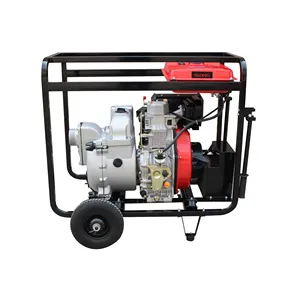
Diesel Mud pumps (temporally not available due to lack of engines 12/1/22) features 2-stage, 44 to 1 gear reduction with a large diameter output gear and heavy duty ball bearing construction. Often referred to as Mud pumps or Sludge pumps, diaphragm trash pumps are designed to pump mud, slurry, sewage, and thick liquids that have the ability to flow. Hatz Diesel engine 1B20.
Built-in molded polyurethane flapper/check valve assures self-priming to 20 feet after initial prime. Heavy duty gear box is designed to operate pumps at 40 strokes per minute for electric motor. Each unit includes a 3" NPT steel suction strainer, two 3" NPT nipples, and wheel kit with 10" semi-pneumatic transport wheels for portability. Pumps are designed for use with non-flammable liquids which are compatible with pump component materials. Suction and discharge port size cannot be reduced.
Suction and discharge port size cannot be reduced. Due to positive pumping action of diaphragm pumps, by all mfr"s, the discharge is recommended to only be 25FT long unless oversized. Discharge can not be restricted. There is no relief valve.

This invention relates to the circulation of fluid between the surface of a subterranean well and the bore hole and more specifically relates to the simultaneous control of drilling fluid circulation or mud pumps and a choke communicating with the pump.
Conventional apparatus used in rotary drilling operations includes a drilling fluid circulation pump or mud pump used to circulate drilling fluids from the surface through the well bore. These fluids are used to remove cuttings made by a rotary drill. In normal drilling fluid or mud circulation, the drilling fluid is pumped down through the drill pipe, discharged through the bit and returns to the surface in the annular space outside the drill pipe and inside the drill hole and casing placed in the well. The rate of drilling fluid circulation is determined by the necessary upward flow velocity required for removing cavings and drill cuttings from the hole and by the jetting requirements of the bit. The inherent advantage of the rotary system of drilling is that a fluid is circulated for the purpose of removing drill cuttings and maintaining a hole in such condition that the drill string can be withdrawn readily and returned to the bottom whenever necessary.
During conventional drilling it is not uncommon to encounter a sudden pressure increase or kick caused by the release of downhole liquids or gases under pressure which can affect drilling fluid circulation. When a kick is encountered, it can be necessary to vary the rate at which drilling fluid is injected into the well or to change the weight of the drilling fluid. A choke, in communication with the pump, is used to prevent significant pressure changes in conjunction with a change in the speed of operation of the mud pumps. For example, a significant increase in downhole pressure occurring as a result of an increase in the drilling fluid circulation can conceivably fracture the producing formation causing serious damage.
In normal drilling operations, the mud pumps are controlled by the driller, using a driller"s console located at the driller"s station on a rig to monitor relevant drilling parameters, including the speed of the mud pumps. Furthermore, conventional well control circulation operations also require manipulation of the choke to regulate or control the fluid pressure, especially during changes in the speed of the mud pump. On a conventional drilling rig, the choke is normally controlled from a choke console, which can be positioned on the drilling floor, at a position remote from the normal location of a driller"s console on a surface rig. Simultaneous control of both the mud pumps and the choke requires communication between the driller and one manning the choke console. Such communication is difficult, especially on engine driven drilling rigs. The noise and the use of different types of gauges on a rig cause confusion and makes such communication difficult, especially on engine driven drilling rigs. Furthermore, a more accurate gauge for pump strokes rate is conventionally located at the choke console, but conventional apparatus provide no means for using this more accurate gauge at the choke console to control the pumps. In a crisis situation, where the drilling crew is attempting to control the well, increased emphasis is placed on efficient communication and operation, which is difficult using prior art devices.
Apparatus for controlling the circulation of well control or kill fluid in a subterranean well includes a pump and a choke communicating with the pump to deliver drilling fluids from the surface of the well into the bore hole and return to the fluid handling equipment. Apparatus for monitoring the condition of the pump is normally employed at the driller"s console on the drilling rig and such pump monitoring apparatus includes a conventional pump control for regulating the speed and operation of the drilling fluid pumps. These pump controls can consist of pneumatic control valves or rheostats.
While control of the pump can be effected from the driller"s console, control of the choke can be simultaneously effected using a choke control apparatus located at a choke console, normally located on the drilling floor at a location remote from the driller"s console. A second pump control apparatus, again consisting of a conventional device, such as a pneumatic control valve or a rheostat, is located at the choke monitoring console and can be used to regulate pump speed and operation in the same manner as the first pump control apparatus located at the driller"s console. Apparatus is provided for overriding the first pump control upon transmission of a signal from the second pump control. Such apparatus can comprise a pneumatic valve unit or an electrical relay consisting of normally closed and normally open switches which change state upon actuation of the second pump control apparatus. In the preferred embodiment of this invention, the overriding signal is the same as the pump control signal. When this pump control signal is transmitted, a valve or relay functions to override the first pump control apparatus. Signals transmitted from the second pump control located at the choke console can then be transmitted to the pumps.
In the preferred embodiment of this invention, the overriding apparatus comprises a portion of an interface network located in the driller"s console, and the second pump control signal is transmitted from the choke console through the driller"s console and subsequently to the drilling fluid or mud pumps. In this manner, control of both the pump and the choke can be transferred to the same location on the drilling rig to provide for better control over both the rate of circulation of the drilling fluids and over the pressure maintained in the bore hole. Such centralized control is quite useful in certain situations, such as when a kick is encountered.
The preferred embodiments of the invention depicted herein are intended for use with conventional driller"s consoles and choke consoles employed on diesel or electrically powered rigs commonly used for drilling subterranean wells. The interface network and remote pump control apparatus employed in the choke console are consistent with conventional commercially available components of driller"s consoles and choke console.
FIG. 1 shows the conventional location of the driller"s console 2 and choke console 4 between which signals are transmitted to regulate or control both mud pumps 6 and the choke 8. The choke console 4 located proximate to the choke 8 separately controls the operation of the choke. The driller"s console 2 includes means for separately controlling the mud pumps 6 and signals may be transmitted from the choke console to the driller"s console for regulating the operation and speed of the mud pump. It can be seen from FIG. 2 that in the preferred embodiment of this invention the choke console controls the pumps by signals transmitted through the driller"s console 2. The transmission of signals between the various components shown in FIG. 2 can be by any of a number of conventional means, such as by electrical signals, by pneumatic or hydraulic signals, by fiber optic signals, by power line modulation, or in any other conventional form suitable for use on a drilling rig. A pneumatic control network for use with a diesel powered rig and an electrical interface network for use within an electrically powered drilling rig will be described herein.
FIGS. 3-5 depict the operation of a pneumatic interface network for a diesel powered rig. Only those portions of the pump control and the interface network relevant to the control of drilling fluid, circulating or mud pumps are depicted. Numerous other components are employed in a driller"s console or in a choke console. Such components are, however, conventional and the components shown in FIG. 3 are compatible with other conventional components controlling the operation of a drilling rig. The pneumatic interface network for the diesel powered rig shown in FIG. 3 is intended for use in controlling two mud pumps. On conventional drilling rigs, two or more mud pumps are employed, although it is common practice to use only a single mud pump at a time, retaining the other mud pumps for redundancy and/or for emergency situations. The two pneumatic control valves 12 and 26 contained within the driller"s console comprise conventional valves commonly employed in driller"s console. Valves manufactured by American Standard having a pressure range of 0 to 100 psi for clutch and throttle signals represent one conventional valve for controlling the mud pump. A plurality of shuttle valves 18, 20, 32 and 34, each comprising a dual input-single output valve, are employed on opposite sides of each of the first or main pneumatic control valves 12 and 26 for controlling the operation of the mud pumps. Shuttle valves 18, 20, 32 and 34 may comprise conventional valves, such as the P-54350-2 shuttle valve manufactured by Wabco, an American Standard Company. Of course other similar valves could be used to form the isolation function of these shuttle valves. Valve 70, also located at the driller"s console, comprises a four element stack valve unit consisting of valve elements 70a, 70b, 70c and 70d. Pneumatic valves 70 each comprise spring loaded, dual input, single output valves forming a valve stack 70. Individual valves are of conventional construction and comprise valves such as the A222PS valves manufactured by ARO Inc. which can be secured together by using an MKN stacking kit and an isolator plate manufactured by ARO Inc.
The rig air input from conduit 64 into stack valve units 70a and 70b passes through lines 66 and 68 respectively to the pump control valves 12 and 26 when stack valves 70a and 70b are in the open position. Essentially, the stack valve units 70a and 70b are connected in parallel to the rig air source 64. The output conduits 61 and 62 leading from the stack valve units 70c and 70d are respectively connected to shuttle valves 18 and 34. Communication is normally established between throttle line 48 and valves 18 and 34 through the stack valve units 70c and 70d when the spring loaded valves are in their normally open position.
FIG. 3 depicts a condition in which the mud pumps 6 and 6" can be controlled by using the first or primary mud pump controllers 12 and 26. It should be understood that in an actual practice, only one pump is normally used. Solid lines have been used to indicate that pneumatic signals communicate through the line, while dashed lines indicate that the line has been disabled and no signal is transmitted. As shown by the solid lines in FIG. 3, pressure in line 64, which is obtained from a source of rig air, communicates through the normally open stack valves 70a and 70b to lines 66 and 68 respectively. Rig air is then applied to pneumatic control valves 12 and 26. Referring to control valve 12, the presence of rig air at the input of this first control valve permits clutch and throttle signals to be generated in lines 14 and 16 respectively. Since the choke console pneumatic control valve is in the off position, as shown in FIG. 3, and there is no pressure in lines 48, 50 and 52, a pneumatic signal is applied in only one of the dual input ports of shuttle valves 18 and 20. A pneumatic clutch signal in line 14 can be transmitted through shuttle valve 20 and clutch line 22 directly to the drilling fluid or mud pump. Similarly, a throttle signal in line 16 would be transmitted through shuttle valve 18 and line 24 to the pump. Thus the pneumatic throttle and clutch signals to pump 6 are employed to control the operating speed of an internal combustion engine, for example, driving pump 6 and an operating clutch to engage or disengage the pump as desired or required.
FIG. 4 shows the condition in which the choke console pneumatic control valve 46 is actuated to apply a pneumatic signal in clutch line 52 and in throttle line 48. Pneumatic control valve 46 is of the type that actuation of a control lever in one direction will induce a clutch signal during initial movement and thereafter will produce a throttle signal. The pneumatic signal in clutch line 52 acts through lines 54 and 56 on the actuator ports of stack valve units 70a and 70d. Pressure applied at the actuator ports plugs the input lines to stack valve units 70a and 70d. Thus the rig air from line 64 is plugged by stack valve unit 70a thus disabling the first mud pump control valve 12 which comprises the primary means of regulating the mud pump 6 from the driller"s console. The pneumatic signal in line 52 is, however, transmitted to the second input port of shuttle valve 20. Since there is no pressure in line 14, any clutch signal in line 52 at shuttle valve 20 will be transmitted through line 22. The pneumatic signal in line 52 communicating with line 56 also disables the throttle input to stack valve unit 70d isolating shuttle valve 34 from the throttle line 48. Stack valve unit 70c, however, remains open and the pneumatic signal in throttle line 48 will be transmitted through line 61 to shuttle valve 18. This pneumatic signal in line 61 is in turn transmitted through throttle line 24 to the first mud pump. Similarly, the stack valve unit 70b remains open and rig air from conduit 64 flows through line 68 to the secondary driller mud pump control valve 26.
FIG. 5 shows the same pneumatic control circuit in which the choke console pump control valve 46 has been actuated to generate a pneumatic clutch C2 signal in line 50. This pneumatic signal in line 50 communicates through lines 58 and 60 to the actuating ports of stack valve units 70b and 70c to close the input ports from the rig air conduit 64 and from the throttle line 48 respectively. Valve units 70a and 70d, however, remain open. Rig air can thus be applied to pump control valve 12 and the pneumatic signal in throttle line 48 can be transmitted through stack valve unit 70d to one input port of shuttle valve 34. Similarly, the pneumatic signal in clutch C2 line 50 is transmitted to an input port of shuttle valve 32. A clutch signal derived from the pneumatic control valve 46 can thus be applied through line 36 to the second mud pump. Similarly, a throttle signal 38 determined by the position of pneumatic control valve 46 can be applied through shuttle valve 34 and line 38 to the second mud pump. Choke console pneumatic control valve 46 is of the type that actuation of an input lever in a first direction will apply a signal in clutch C1 line 52 and in throttle line 48, while actuation of the control valve unit in the opposite direction will result in the presence of a pneumatic signal in clutch C2 line 50 and in the throttle line 48. It will be understood that separate choke control elements are contained within the choke console for positioning the choke in the proper position. When the apparatus is in the configurations of FIGS. 4 and 5, the choke control valve 46 can also be used to control either mud pump 6 or mud pump 6".
FIG. 6 shows an electrical interface network for use with an electrically powered rig. Again, separate drillers and choke consoles can be used in the same manner as shown in FIG. 2. In this electrically powered network, rheostat 72 provides a control signal through path 88 and normally closed relay 84a and line 86 to an SCR housing for controlling the operation and speed of a single mud pump. A second rheostat 90 located on the choke console is normally isolated from SCR housing line 86 by a normally open relay 84b. The configuration of FIG. 6 shows the conventional operation of the mud pump 6 by means of the pump controlling rheostat 72 located in the driller"s console. When it is desired to control the mud pump by use of the choke mud pump control rheostat 90, switches 76 and 77 are closed. When switch 76 is closed, the relay 84 changes state and the normally open relay 84b is closed permitting regulation of the mud pump by the choke console mud pump rheostat 90. Closure of switch 76 results in the application of a voltage to the relay 84 thus changing the state of relays 84a and 84b to override the signal from the driller"s console mud pump rheostat 72 when it is desired to control the mud pump from the remote position of the choke console. Note that the common +V line 80 and ground line 82 lead between the driller"s console and the choke console. If for any reason these lines are severed, control of the mud pump automatically reverts to the driller"s console rheostat 72. Thus, the mud pump 6 or mud pump 6" can be controlled from the driller"s console or through the remote position of the choke console depending upon closure of electrical switch 76.
The VERSADRIL diesel-base drilling fluid system from M-I SWACO resists contaminants, is solids tolerant, and has a low coefficient of friction to provide good lubricity. As a result, the system promotes wellbore stability, bolsters ROP, and improves drilling economics.

This rig features a Mission 4-by-5 centrifugal pump. Courtesy of Higgins Rig Co.Returning to the water well industry when I joined Schramm Inc. last year, I knew that expanding my mud pump knowledge was necessary to represent the company"s mud rotary drill line properly. One item new to me was the centrifugal mud pump. What was this pump that a number of drillers were using? I had been trained that a piston pump was the only pump of any ability.
As I traveled and questioned drillers, I found that opinions of the centrifugal pumps varied. "Best pump ever built," "What a piece of junk" and "Can"t drill more than 200 feet with a centrifugal" were typical of varying responses. Because different opinions had confused the issue, I concluded my discussions and restarted my education with a call to a centrifugal pump manufacturer. After that conversation, I went back to the field to continue my investigation.
For the past eight months, I have held many discussions and conducted field visits to understand the centrifugal pump. As a result, my factual investigation has clearly proved that the centrifugal pump has a place in mud rotary drilling. The fact also is clear that many drilling contractors do not understand the correct operational use of the pump. Following are the results of my work in the field.
High up-hole velocity - High pump flow (gpm) moves cuttings fast. This works well with lower viscosity muds - reducing mud expense, mixing time and creating shorter settling times.
Able to run a desander - The centrifugal"s high volume enables a desander to be operated off the pump discharge while drilling without adding a dedicated desander pump.
6. Sticky clays will stall a centrifugal pump"s flow. Be prepared to reduce your bit load in these conditions and increase your rpm if conditions allow. Yes, clays can be drilled with a centrifugal pump.
7. Centrifugal pumps cannot pump muds over 9.5 lbs./gal. Centrifugal pumps work best with a 9.0 lbs./gal. mud weight or less. High flow rate move cuttings, not heavy mud.
The goal of this article has been to increase awareness of the value of the centrifugal pump and its growing use. Although the centrifugal pump is not flawless, once its different operating techniques are understood, drilling programs are being enhanced with the use of this pump.
If you wish to learn more, please talk directly to centrifugal pump users. Feel free to call me at 314-909-8077 for a centrifugal pump user list. These drillers will gladly share their centrifugal pump experiences.

The LS300H takes the hydraulic drill line to new depths thanks to a powerful 13-horsepower mud pump. The water well drill features the same user-friendly design and hassle-free operation as the LS200H, but with a drilling depth of up to 300 feet. Its heavy-duty welded steel frame and re-enforced table base provide added durability while the drill’s powerful hydraulics delivers pull-back and push-down forces up to 5,000 pounds. The rig’s three-way ball valve enables quick bypass mudflow when adding pipe, and the swivel base design moves the rotary aside to access the borehole.

OBS see new model. Diesel Mud pumps features 2-stage, 44 to 1 gear reduction with a large diameter output gear and heavy duty ball bearing construction. Often referred to as Mud pumps or Sludge pumps, diaphragm trash pumps are designed to pump mud, slurry, sewage, and thick liquids that have the ability to flow. Hatz Diesel engine 1B20.
Built-in molded polyurethane flapper/check valve assures self-priming to 20 feet after initial prime. Heavy duty gear box is designed to operate pumps at 40 strokes per minute for electric motor. Each unit includes a 3" NPT steel suction strainer, two 3" NPT nipples, and wheel kit with 10" semi-pneumatic transport wheels for portability. Pumps are designed for use with non-flammable liquids which are compatible with pump component materials. Suction and discharge port size cannot be reduced.
Suction and discharge port size cannot be reduced. Due to positive pumping action of diaphragm pumps, by all mfr"s, the discharge is recommended to only be 25FT long unless oversized. Discharge can not be restricted. There is no relief valve.

For drilling companies with the need to pump slurries with bentonite, concrete, and other thick mud, Elepump triplex, high pressure piston mud pumps are the ideal choice for long life and minimal maintenance.
Featuring superior construction and high quality materials, Elepump mud pumps are built to last. They require minimal maintenance, so your costs stay low so and your drilling operations stay profitable.
The KT-45 mud pump is the most compact of the whole range of Elepump pressure pumps. This small capacity pump is still mighty enough to pack a big punch, with enough flow for drilling up to HQ sizes. It is very light and very maneuverable, making it a great choice for geotechnical drilling, fly jobs or heliportable jobs. Elepump mud pumps can be configured for diesel, gas, electric and air power.
The KF-50M is the pump to choose if you want a pump you can count on to keep pumping without missing a beat. This powerful pump is a standard size and can handle all slurries including bentonite, concrete and more. With its stainless steel ball and seat style valves, it is the ideal choice for pumping grit, cement, chunks of rock and other hard material, without the worry of damage to fragile parts. Elepump mud pumps can be configured for diesel, gas, electric and air power.

Pumps tend to be one of the biggest energy consumers in industrial operations. Pump motors, specifically, require a lot of energy. For instance, a 2500 HP triplex pump used for frac jobs can consume almost 2000 kW of power, meaning a full day of fracking can cost several thousand dollars in energy costs alone!
So, naturally, operators should want to maximize energy efficiency to get the most for their money. Even a 1% improvement in efficiency can decrease annual pumping costs by tens of thousands of dollars. The payoff is worth the effort. And if you want to remotely control your pumps, you want to keep efficiency in mind.
In this post, we’ll point you in the right direction and discuss all things related to pump efficiency. We’ll conclude with several tips for how you can maintain pumping efficiency and keep your energy costs down as much as possible.
In simple terms, pump efficiency refers to the ratio of power out to power in. It’s the mechanical power input at the pump shaft, measured in horsepower (HP), compared to the hydraulic power of the liquid output, also measured in HP. For instance, if a pump requires 1000 HP to operate and produces 800 HP of hydraulic power, it would have an efficiency of 80%.
Remember: pumps have to be driven by something, i.e., an electric or diesel motor. True pump system efficiency needs to factor in the efficiency of both the motor AND the pump.
Consequently, we need to think about how electrical power (when using electric motors) or heat power (when using combustion engines) converts into liquid power to really understand pump efficiency.
Good pump efficiency depends, of course, on pump type and size. High-quality pumps that are well-maintained can achieve efficiencies of 90% or higher, while smaller pumps tend to be less efficient. In general, if you take good care of your pumps, you should be able to achieve 70-90% pump efficiency.
AC motors can achieve 90%+ efficiency when converting electrical to mechanical energy. Combustion engines are much less efficient, with typical efficiency ratings coming in at ~20% for gasoline and ~40% for diesel. Your choice of engine or motor type will depend on the availability and cost of fuel or electricity in your area.
Now that we have a better understanding of the pump efficiency metric, let’s talk about how to calculate it. The mechanical power of the pump, or the input power, is a property of the pump itself and will be documented during the pump setup. The output power, or hydraulic power, is calculated as the liquid flow rate multiplied by the "total head" of the system.
IMPORTANT: to calculate true head, you also need to factor in the work the pump does to move fluid from the source. For example, if the source water is below the pump, you need to account for the extra work the pump puts in to draw source water upwards.
*Note - this calculation assumes the pump inlet is not pressurized and that friction losses are minimal. If the pump experiences a non-zero suction pressure, or if there is significant friction caused by the distance or material of the pipe, these should be factored in as well.
You"ll notice that the elevation head is minimal compared to the discharge pressure, and has minimal effect on the efficiency of the pump. As the elevation change increases or the discharge pressure decreases, however, elevation change will have a greater impact on total head.
Obviously, that’s a fair amount of math to get at the pump efficiency, considering all of the units conversions that need to be done. To avoid doing these calculations manually, feel free to use our simple pump efficiency calculator.
Our calculations use static variables (pump-rated horsepower and water source elevation) and dynamic variables (discharge flow and pressure). To determine pump efficiency, we need to measure the static variables only once, unless they change.
If you want to measure the true efficiency of your pump, taking energy consumption into account, you could add an electrical meter. Your meter should consist of a current transducer and voltage monitor (if using DC) for electrical motors or a fuel gauge for combustion. This would give you a true understanding of how pump efficiency affects energy consumption, and ultimately your bank account.
Up until this point, we’ve covered the ins and outs of how to determine pump efficiency. We’re now ready for the exciting stuff - how to improve pump efficiency!
One of the easiest ways to improve pump efficiency is to actually monitor pumps for signs of efficiency loss! If you monitor flow rate and discharge (output power) along with motor current or fuel consumption, you’ll notice efficiency losses as soon as they occur. Simply having pump efficiency information on hand empowers you to take action.
Another way to increase efficiency is to keep pumps well-maintained. Efficiency losses mostly come from mechanical defects in pumps, e.g., friction, leakages, and component failures. You can mitigate these issues through regular maintenance that keeps parts in working order and reveals impending failures. Of course, if you are continuously monitoring your pumps for efficiency drops, you’ll know exactly when maintenance is due.
You can also improve pump efficiency by keeping pumps lubricated at all times. Lubrication is the enemy of friction, which is the enemy of efficiency (“the enemy of my enemy is my friend…”).
A fourth way to enhance pump efficiency is to ensure your pumps and piping are sized properly for your infrastructure. Although we’re bringing this up last, it’s really the first step in any pumping operation. If your pumps and piping don’t match, no amount of lubricant or maintenance will help.
In this post, we’ve given you the full rundown when it comes to calculating and improving pump efficiency. You can now calculate, measure, and improve pump efficiency, potentially saving your business thousands of dollars annually on energy costs.
For those just getting started with pump optimization, we offer purpose-built, prepackaged solutions that will have you monitoring pump efficiency in minutes, even in hazardous environments.

In geotechnical engineering, drilling fluid, also called drilling mud, is used to aid the drilling of boreholes into the earth. Often used while drilling oil and natural gas wells and on exploration drilling rigs, drilling fluids are also used for much simpler boreholes, such as water wells. One of the functions of drilling mud is to carry cuttings out of the hole.
The three main categories of drilling fluids are water-based muds (WBs), which can be dispersed and non-dispersed; non-aqueous muds, usually called oil-based muds (OBs); and gaseous drilling fluid, in which a wide range of gases can be used. Along with their formatives, these are used along with appropriate polymer and clay additives for drilling various oil and gas formations.
Water-based mud (WBM): Most water-based mud systems begin with water, then clays and other chemicals are added to create a homogeneous blend with viscosity between chocolate milk and a malt. The clay is usually a combination of native clays that are suspended in the fluid while drilling, or specific types of clay processed and sold as additives for the WBM system. The most common type is bentonite, called "gel" in the oilfield. The name likely refers to the fluid viscosity as very thin and free-flowing (like chocolate milk) while being pumped, but when pumping is stopped, the static fluid congeals to a "gel" that resists flow. When adequate pumping force is applied to "break the gel," flow resumes and the fluid returns to its free-flowing state. Many other chemicals (e.g. potassium formate) are added to a WBM system to achieve desired effects, including: viscosity control, shale stability, enhance drilling rate of penetration, and cooling and lubricating of equipment.
Oil-based mud (OBM): Oil-based mud has a petroleum based fluid such as diesel fuel. Oil-based muds are used for increased lubricity, enhanced shale inhibition, and greater cleaning abilities with less viscosity. Oil-based muds also withstand greater heat without breaking down. The use of oil-based muds has special considerations of cost, environmental concerns such as disposal of cuttings in an appropriate place, and the exploratory disadvantages of using oil-based mud, especially in wildcat wells. Using an oil-based mud interferes with the geochemical analysis of cuttings and cores and with the determination of API gravity because the base fluid cannot be distinguished from oil that is returned from the formation.
Synthetic-based fluid (SBM) (Otherwise known as Low Toxicity Oil Based Mud or LTOBM): Synthetic-based fluid is a mud in which the base fluid is a synthetic oil. This is most often used on offshore rigs because it has the properties of an oil-based mud, but the toxicity of the fluid fumes are much less. This is important when the drilling crew works with the fluid in an enclosed space such as an offshore drilling rig. Synthetic-based fluid poses the same environmental and analysis problems as oil-based fluid.
On a drilling rig, mud is pumped from the casing, where it emerges from the top. Cuttings are then filtered out with either a shale shaker or the newer shale conveyor technology, and the mud returns to the mud pits. The mud pits allow the drilled "fines" to settle and the mud to be treated by adding chemicals and other substances.
The returning mud may contain natural gases or other flammable materials which will collect in and around the shale shaker / conveyor area or in other work areas. Because of the risk of a fire or an explosion if they ignite, special monitoring sensors and explosion-proof certified equipment is commonly installed, and workers are trained in safety precautions. The mud is then pumped back down the hole and further re-circulated. After testing, the mud is treated periodically in the mud pits to ensure it has desired properties that optimize and improve drilling efficiency and borehole stability.
Drilling fluid carries the rock excavated by the drill bit up to the surface. Its ability to do so depends on cutting size, shape, and density, and speed of fluid traveling up the well (annular velocity). These considerations are analogous to the ability of a stream to carry sediment. Large sand grains in a slow-moving stream settle to the stream bed, while small sand grains in a fast-moving stream are carried along with the water. The mud viscosity is an important property, as cuttings will settle to the bottom of the well if the viscosity is too low.
Most drilling muds are thixotropic (viscosity increases when static). This characteristic keeps the cuttings suspended when the mud is not flowing during, for example, maintenance.
High density fluids may clean holes adequately even with lower annular velocities (by increasing the buoyancy force acting on cuttings) but may have a negative impact if mud weight exceeds that needed to balance the pressure of surrounding rock (formation pressure), so mud weight is not usually increased for hole cleaning.
For effective solids controls, drill solids must be removed from mud on the 1st circulation from the well. If re-circulated, cuttings break into smaller pieces and are more difficult to remove.
If formation pressure increases, mud density should be increased to balance pressure and keep the wellbore stable. The most common weighting material is baryte. Unbalanced formation pressure will cause an unexpected influx (also known as a kick) of formation fluids into the wellbore possibly leading to a blowout from pressurized formation fluid.
In practice, mud density should be limited to the minimum necessary for well control and wellbore stability. If too great it may fracture the formation.
Mud column pressure must exceed formation pressure, in this condition mud filtrate invades the formation, and a filter cake of mud is deposited on the wellbore wall.
Depending on the mud system in use, a number of additives can improve the filter cake (e.g. bentonite, natural & synthetic polymer, asphalt and gilsonite).
Chemical composition and mud properties must combine to provide a stable wellbore. Weight of the mud must be within the necessary range to balance the mechanical forces.
In shales, mud weight is usually sufficient to balance formation stress, as these wells are usually stable. With water base mud, chemical differences can cause interactions between mud & shale that lead to softening of the native rock. Highly fractured, dry, brittle shales can be extremely unstable (leading to mechanical problems).
Various chemical inhibitors can control mud / shale interactions (calcium, potassium, salt, polymers, asphalt, glycols and oil – best for water sensitive formations)
Lubrication based on the coefficient of friction.("Coefficient of friction" is how much friction on side of wellbore and collar size or drill pipe size to pull stuck pipe) Oil- and synthetic-based mud generally lubricate better than water-based mud (but the latter can be improved by the addition of lubricants).
Drilling fluids also support portion of drill-string or casing through buoyancy. Suspend in drilling fluid, buoyed by force equal to weight (or density) of mud, so reducing hook load at derrick.
Hydraulic energy provides power to mud motor for bit rotation and for MWD (measurement while drilling) and LWD (logging while drilling) tools. Hydraulic programs base on bit nozzles sizing for available mud pump horsepower to optimize jet impact at bottom well.
Mud loggers examine cuttings for mineral composition, visual sign of hydrocarbons and recorded mud logs of lithology, ROP, gas detection or geological parameters.
Mud should have thin, slick filter cake, with minimal solids in filter cake, wellbore with minimal cuttings, caving or bridges will prevent a good casing run to bottom. Circulate well bore until clean.
Mud low viscosity, mud parameters should be tolerant of formations being drilled, and drilling fluid composition, turbulent flow - low viscosity high pump rate, laminar flow - high viscosity, high pump rate.
Water-based drilling mud most commonly consists of bentonite clay (gel) with additives such as barium sulfate (baryte), calcium carbonate (chalk) or hematite. Various thickeners are used to influence the viscosity of the fluid, e.g. xanthan gum, guar gum, glycol, carboxymethylcellulose, polyanionic cellulose (PAC), or starch. In turn, deflocculants are used to reduce viscosity of clay-based muds; anionic polyelectrolytes (e.g. acrylates, polyphosphates, lignosulfonates (Lig) or tannic acid derivates such as Quebracho) are frequently used. Red mud was the name for a Quebracho-based mixture, named after the color of the red tannic acid salts; it was commonly used in the 1940s to 1950s, then was made obsolete when lignosulfonates became available. Other components are added to provide various specific functional characteristics as listed above. Some other common additives include lubricants, shale inhibitors, fluid loss additives (to control loss of drilling fluids into permeable formations). A weighting agent such as baryte is added to increase the overall density of the drilling fluid so that sufficient bottom hole pressure can be maintained thereby preventing an unwanted (and often dangerous) influx of formation fluids
Freshwater mud: Low pH mud (7.0–9.5) that includes spud, bentonite, natural, phosphate treated muds, organic mud and organic colloid treated mud. high pH mud example alkaline tannate treated muds are above 9.5 in pH.
Water based drilling mud that represses hydration and dispersion of clay – There are 4 types: high pH lime muds, low pH gypsum, seawater and saturated salt water muds.
Low solids mud: These muds contain less than 3–6% solids by volume and weight less than 9.5 lbs/gal. Most muds of this type are water-based with varying quantities of bentonite and a polymer.
Oil based mud: Oil based muds contain oil as the continuous phase and water as a contaminant, and not an element in the design of the mud. They typically contain less than 5% (by volume) water. Oil-based muds are usually a mixture of diesel fuel and asphalt, however can be based on produced crude oil and mud
"Mud engineer" is the name given to an oil field service company individual who is charged with maintaining a drilling fluid or completion fluid system on an oil and/or gas drilling rig.mud engineer, or more properly drilling fluids engineer, is critical to the entire drilling operation because even small problems with mud can stop the whole operations on rig. The internationally accepted shift pattern at off-shore drilling operations is personnel (including mud engineers) work on a 28-day shift pattern, where they work for 28 continuous days and rest the following 28 days. In Europe this is more commonly a 21-day shift pattern.
In offshore drilling, with new technology and high total day costs, wells are being drilled extremely fast. Having two mud engineers makes economic sense to prevent down time due to drilling fluid difficulties. Two mud engineers also reduce insurance costs to oil companies for environmental damage that oil companies are responsible for during drilling and production. A senior mud engineer typically works in the day, and a junior mud engineer at night.
The cost of the drilling fluid is typically about 10% (may vary greatly) of the total cost of drilling a well, and demands competent mud engineers. Large cost savings result when the mud engineer and fluid performs adequately.
The compliance engineer is the most common name for a relatively new position in the oil field, emerging around 2002 due to new environmental regulations on synthetic mud in the United States. Previously, synthetic mud was regulated the same as water-based mud and could be disposed of in offshore waters due to low toxicity to marine organisms. New regulations restrict the amount of synthetic oil that can be discharged. These new regulations created a significant burden in the form of tests needed to determine the "ROC" or retention on cuttings, sampling to determine the percentage of crude oil in the drilling mud, and extensive documentation. No type of oil/synthetic based mud (or drilled cuttings contaminated with OBM/SBM) may be dumped in the North Sea. Contaminated mud must either be shipped back to shore in skips or processed on the rigs.
Clark, Peter E. (1995-01-01). "Drilling Mud Rheology and the API Recommended Measurements". SPE Production Operations Symposium. Society of Petroleum Engineers. doi:10.2118/29543-MS. ISBN 9781555634483.


 8613371530291