
mud pump capacity free sample

The 2,200-hp mud pump for offshore applications is a single-acting reciprocating triplex mud pump designed for high fluid flow rates, even at low operating speeds, and with a long stroke design. These features reduce the number of load reversals in critical components and increase the life of fluid end parts.
The pump’s critical components are strategically placed to make maintenance and inspection far easier and safer. The two-piece, quick-release piston rod lets you remove the piston without disturbing the liner, minimizing downtime when you’re replacing fluid parts.

I’ve run into several instances of insufficient suction stabilization on rigs where a “standpipe” is installed off the suction manifold. The thought behind this design was to create a gas-over-fluid column for the reciprocating pump and eliminate cavitation.
When the standpipe is installed on the suction manifold’s deadhead side, there’s little opportunity to get fluid into all the cylinders to prevent cavitation. Also, the reciprocating pump and charge pump are not isolated.
Installing a suction stabilizer from the suction manifold port supports the manifold’s capacity to pull adequate fluid and eliminates the chance of manifold fluid deficiency, which ultimately prevents cavitation.
The suction stabilizer’s compressible feature is designed to absorb the negative energies and promote smooth fluid flow. As a result, pump isolation is achieved between the charge pump and the reciprocating pump.
The isolation eliminates pump chatter, and because the reciprocating pump’s negative energies never reach the charge pump, the pump’s expendable life is extended.
Investing in suction stabilizers will ensure your pumps operate consistently and efficiently. They can also prevent most challenges related to pressure surges or pulsations in the most difficult piping environments.
Centerline Manu-facturing introduces the CLM 7.5 x 10D hydraulic mud pump, a pump which utilizes common fluid end parts. Its advantages are said to be its flow capacity, rated pressure, size and weight. It is designed to pump 100 percent more rated flow than a standard 5x6 and up to 3.25 times the rated pressure. However, it only has a third of the weight and 77 percent of the length.

When choosing a size and type of mud pump for your drilling project, there are several factors to consider. These would include not only cost and size of pump that best fits your drilling rig, but also the diameter, depth and hole conditions you are drilling through. I know that this sounds like a lot to consider, but if you are set up the right way before the job starts, you will thank me later.
Recommended practice is to maintain a minimum of 100 to 150 feet per minute of uphole velocity for drill cuttings. Larger diameter wells for irrigation, agriculture or municipalities may violate this rule, because it may not be economically feasible to pump this much mud for the job. Uphole velocity is determined by the flow rate of the mud system, diameter of the borehole and the diameter of the drill pipe. There are many tools, including handbooks, rule of thumb, slide rule calculators and now apps on your handheld device, to calculate velocity. It is always good to remember the time it takes to get the cuttings off the bottom of the well. If you are drilling at 200 feet, then a 100-foot-per-minute velocity means that it would take two minutes to get the cuttings out of the hole. This is always a good reminder of what you are drilling through and how long ago it was that you drilled it. Ground conditions and rock formations are ever changing as you go deeper. Wouldn’t it be nice if they all remained the same?
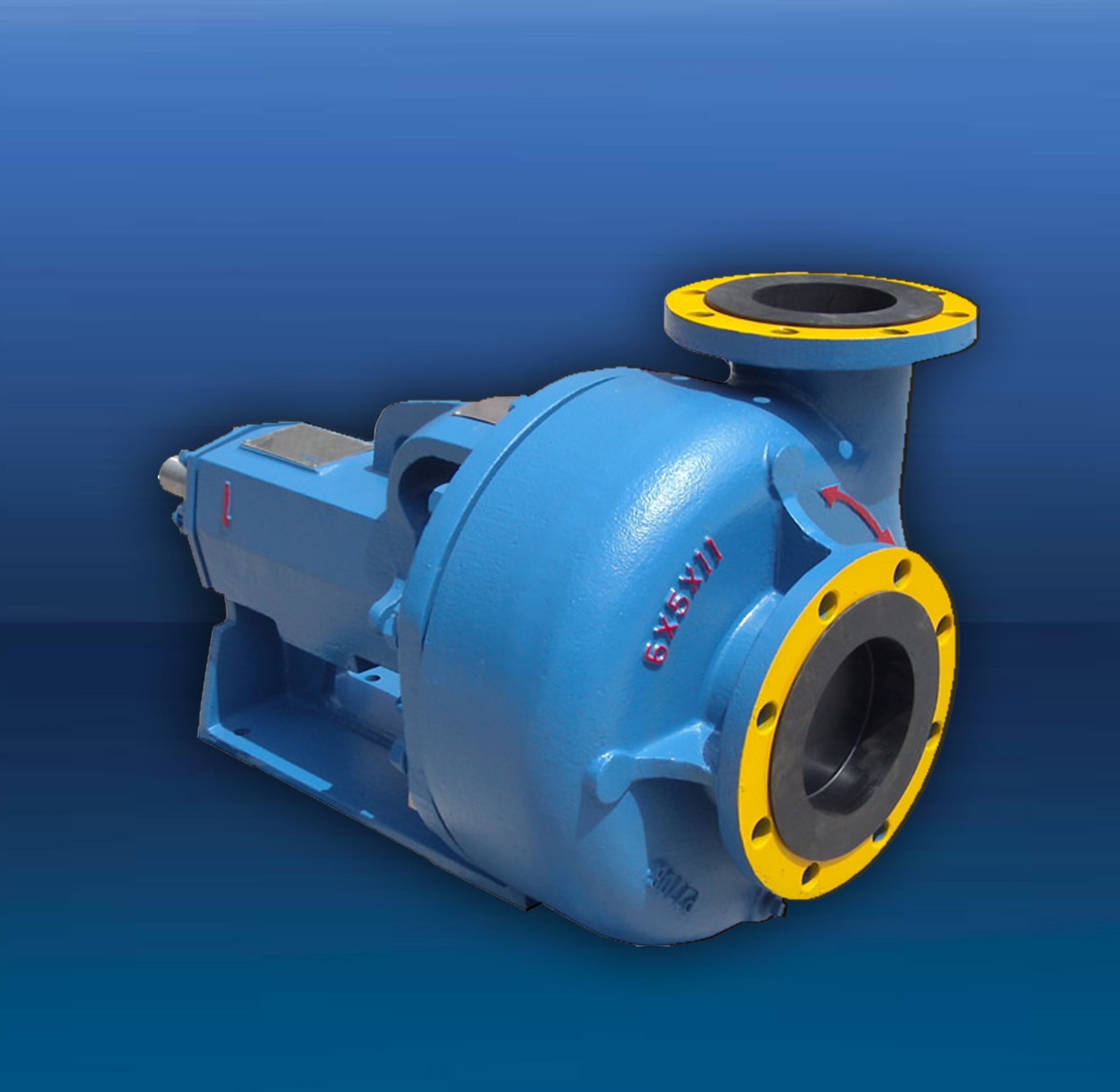
Centrifugal-style mud pumps are very popular in our industry due to their size and weight, as well as flow rate capacity for an affordable price. There are many models and brands out there, and most of them are very good value. How does a centrifugal mud pump work? The rotation of the impeller accelerates the fluid into the volute or diffuser chamber. The added energy from the acceleration increases the velocity and pressure of the fluid. These pumps are known to be very inefficient. This means that it takes more energy to increase the flow and pressure of the fluid when compared to a piston-style pump. However, you have a significant advantage in flow rates from a centrifugal pump versus a piston pump. If you are drilling deeper wells with heavier cuttings, you will be forced at some point to use a piston-style mud pump. They have much higher efficiencies in transferring the input energy into flow and pressure, therefore resulting in much higher pressure capabilities.
Piston-style mud pumps utilize a piston or plunger that travels back and forth in a chamber known as a cylinder. These pumps are also called “positive displacement” pumps because they literally push the fluid forward. This fluid builds up pressure and forces a spring-loaded valve to open and allow the fluid to escape into the discharge piping of the pump and then down the borehole. Since the expansion process is much smaller (almost insignificant) compared to a centrifugal pump, there is much lower energy loss. Plunger-style pumps can develop upwards of 15,000 psi for well treatments and hydraulic fracturing. Centrifugal pumps, in comparison, usually operate below 300 psi. If you are comparing most drilling pumps, centrifugal pumps operate from 60 to 125 psi and piston pumps operate around 150 to 300 psi. There are many exceptions and special applications for drilling, but these numbers should cover 80 percent of all equipment operating out there.
The restriction of putting a piston-style mud pump onto drilling rigs has always been the physical size and weight to provide adequate flow and pressure to your drilling fluid. Because of this, the industry needed a new solution to this age-old issue.
As the senior design engineer for Ingersoll-Rand’s Deephole Drilling Business Unit, I had the distinct pleasure of working with him and incorporating his Centerline Mud Pump into our drilling rig platforms.
In the late ’90s — and perhaps even earlier — Ingersoll-Rand had tried several times to develop a hydraulic-driven mud pump that would last an acceptable life- and duty-cycle for a well drilling contractor. With all of our resources and design wisdom, we were unable to solve this problem. Not only did Miller provide a solution, thus saving the size and weight of a typical gear-driven mud pump, he also provided a new offering — a mono-cylinder mud pump. This double-acting piston pump provided as much mud flow and pressure as a standard 5 X 6 duplex pump with incredible size and weight savings.
The true innovation was providing the well driller a solution for their mud pump requirements that was the right size and weight to integrate into both existing and new drilling rigs. Regardless of drill rig manufacturer and hydraulic system design, Centerline has provided a mud pump integration on hundreds of customer’s drilling rigs. Both mono-cylinder and duplex-cylinder pumps can fit nicely on the deck, across the frame or even be configured for under-deck mounting. This would not be possible with conventional mud pump designs.
The second generation design for the Centerline Mud Pump is expected later this year, and I believe it will be a true game changer for this industry. It also will open up the application to many other industries that require a heavier-duty cycle for a piston pump application.

Rig pump output, normally in volume per stroke, of mud pumps on the rig is one of important figures that we really need to know because we will use pump out put figures to calculate many parameters such as bottom up strokes, wash out depth, tracking drilling fluid, etc. In this post, you will learn how to calculate pump out put for triplex pump and duplex pump in bothOilfield and Metric Unit.

Kverneland, Hege, Kyllingstad, Åge, and Magne Moe. "Development and Performance Testing of the Hex Mud Pump." Paper presented at the SPE/IADC Drilling Conference, Amsterdam, Netherlands, February 2003. doi: https://doi.org/10.2118/79831-MS
There are many different ways to drill a domestic water well. One is what we call the “mud rotary” method. Whether or not this is the desired and/or best method for drilling your well is something more fully explained in this brief summary.
One advantage of drilling with compressed air is that it can tell you when you have encountered groundwater and gives you an indication how much water the borehole is producing. When drilling with water using the mud rotary method, the driller must rely on his interpretation of the borehole cuttings and any changes he can observe in the recirculating fluid. Mud rotary drillers can also use borehole geophysical tools to interpret which zones might be productive enough for your water well.
The mud rotary well drilling method is considered a closed-loop system. That is, the mud is cleaned of its cuttings and then is recirculated back down the borehole. Referring to this drilling method as “mud” is a misnomer, but it is one that has stuck with the industry for many years and most people understand what the term actually means.
The water is carefully mixed with a product that should not be called mud because it is a highly refined and formulated clay product—bentonite. It is added, mixed, and carefully monitored throughout the well drilling process.
The purpose of using a bentonite additive to the water is to form a thin film on the walls of the borehole to seal it and prevent water losses while drilling. This film also helps support the borehole wall from sluffing or caving in because of the hydraulic pressure of the bentonite mixture pressing against it. The objective of the fluid mixture is to carry cuttings from the bottom of the borehole up to the surface, where they drop out or are filtered out of the fluid, so it can be pumped back down the borehole again.
When using the mud rotary method, the driller must have a sump, a tank, or a small pond to hold a few thousand gallons of recirculating fluid. If they can’t dig sumps or small ponds, they must have a mud processing piece of equipment that mechanically screens and removes the sands and gravels from the mixture. This device is called a “shale shaker.”
The driller does not want to pump fine sand through the pump and back down the borehole. To avoid that, the shale shaker uses vibrating screens of various sizes and desanding cones to drop the sand out of the fluid as it flows through the shaker—so that the fluid can be used again.
Some drillers use compressed air to blow off the well, starting at the first screened interval and slowly working their way to the bottom—blowing off all the water standing above the drill pipe and allowing it to recover, and repeating this until the water blown from the well is free of sand and relatively clean. If after repeated cycles of airlift pumping and recovery the driller cannot find any sand in the water, it is time to install a well development pump.
Additional development of the well can be done with a development pump that may be of a higher capacity than what the final installation pump will be. Just as with cycles of airlift pumping of the well, the development pump will be cycled at different flow rates until the maximum capacity of the well can be determined. If the development pump can be operated briefly at a flow rate 50% greater than the permanent pump, the well should not pump sand.
Mud rotary well drillers for decades have found ways to make this particular system work to drill and construct domestic water wells. In some areas, it’s the ideal method to use because of the geologic formations there, while other areas of the country favor air rotary methods.
To learn more about the difference between mud rotary drilling and air rotary drilling, click the video below. The video is part of our “NGWA: Industry Connected” YouTube series:

Cavitation is an undesirable condition that reduces pump efficiency and leads to excessive wear and damage to pump components. Factors that can contribute to cavitation, such as fluid velocity and pressure, can sometimes be attributed to an inadequate mud system design and/or the diminishing performance of the mud pump’s feed system.
When a mud pump has entered full cavitation, rig crews and field service technicians will see the equipment shaking and hear the pump “knocking,” which typically sounds like marbles and stones being thrown around inside the equipment. However, the process of cavitation starts long before audible signs reveal themselves – hence the name “the silent killer.”
Mild cavitation begins to occur when the mud pump is starved for fluid. While the pump itself may not be making noise, damage is still being done to the internal components of the fluid end. In the early stages, cavitation can damage a pump’s module, piston and valve assembly.
The imperceptible but intense shock waves generated by cavitation travel directly from the fluid end to the pump’s power end, causing premature vibrational damage to the crosshead slides. The vibrations are then passed onto the shaft, bull gear and into the main bearings.
If not corrected, the vibrations caused by cavitation will work their way directly to critical power end components, which will result in the premature failure of the mud pump. A busted mud pump means expensive downtime and repair costs.
To stop cavitation before it starts, install and tune high-speed pressure sensors on the mud suction line set to sound an alarm if the pressure falls below 30 psi.
Although the pump may not be knocking loudly when cavitation first presents, regular inspections by a properly trained field technician may be able to detect moderate vibrations and slight knocking sounds.
Gardner Denver offers Pump University, a mobile classroom that travels to facilities and/or drilling rigs and trains rig crews on best practices for pumping equipment maintenance.
Severe cavitation will drastically decrease module life and will eventually lead to catastrophic pump failure. Along with downtime and repair costs, the failure of the drilling pump can also cause damage to the suction and discharge piping.
When a mud pump has entered full cavitation, rig crews and field service technicians will see the equipment shaking and hear the pump ‘knocking’… However, the process of cavitation starts long before audible signs reveal themselves – hence the name ‘the silent killer.’In 2017, a leading North American drilling contractor was encountering chronic mud system issues on multiple rigs. The contractor engaged in more than 25 premature module washes in one year and suffered a major power-end failure.
Gardner Denver’s engineering team spent time on the contractor’s rigs, observing the pumps during operation and surveying the mud system’s design and configuration.
The engineering team discovered that the suction systems were undersized, feed lines were too small and there was no dampening on the suction side of the pump.
Following the implementation of these recommendations, the contractor saw significant performance improvements from the drilling pumps. Consumables life was extended significantly, and module washes were reduced by nearly 85%.
Although pump age does not affect its susceptibility to cavitation, the age of the rig can. An older rig’s mud systems may not be equipped for the way pumps are run today – at maximum horsepower.

American Augers mud pumps are standardstand-alone, self-powered machines thatare the perfect accessories to use with mudmotors, large reamers or whenever moremud volume is needed down hole.* Optional Quiet Pak for optimum noise reduction controlP-600 and P-750 Mud Pumps• allow the operator to get enoughflow to keep the bore flushed cleanof cuttings• are designed with a compact skidmounting and provide a smallfootprint that are ideal for mostdrilling environments.• are compatible with any drill brandmaking them suitable for contractorsoperating a variety of sizes, makesand models of drilling equipment.www.AmericanAugers.com
P-600Mud PumpTypical Flow Rates for Popular Size Mud MotorsBe sure to allow enough extra mud flow to flood the boreMUD MOTOR SIZEFLOW RATE/MINUTEInches Millimeters U.S. Gallons Liters3 3/8 85.72 30 - 120 113.6 - 454.23 1/2 88.9 75 - 160 283.9 - 605.74 3/4 120.6 100 - 250 378.5 - 946.46 3/4 171.4 300 - 600 1,136 - 2,271
What Type of Contractor Should Use aMud Pump?• Users of drilling equipment withpumping capacities of 25 U.S.Gallons (95 L)/minute or largerregardless of soil type or conditions.• Drillers typically making bores thatare greater than 6 1/2 in. (165 mm)diameter and more than 200 ft.(61 m) long.• Owners of mud motors for rockdrilling applications.• Operators in areas where muddisposal is expensive or restricted.Both the P-600 and the P-750should be considered when workingin rock formations where the operatingdrill"s on-board mud pump has fluidlimitedcapacities and cannot produceenough pressure to drive the mud motor.www.AmericanAugers.com
MUD MOTOR SIZEP-750Mud PumpTypical Flow Rates for Popular Size Mud MotorsBe sure to allow enough extra mud flow to flood the boreFLOW RATE/MINUTEInches Millimeters U.S. Gallons Liters3 3/8 85.72 30 - 120 113.6 - 454.23 1/2 88.9 75 - 160 283.9 - 605.74 3/4 120.6 100 - 250 378.5 - 946.46 3/4 171.4 300 - 600 1,136 - 2,2718 203.2 400 - 900 1,514 - 3,407
P-600PERFORMANCE SPECIFICATIONSPower TrainEngine:Caterpillar ® C-15 Tier III Diesel* Tier III or Tier 4i determined by country of purchaseFuel Capacity: 300 U.S. Gallons (1,136 L)Rating:475 HP (354 kW)Transmission: Eaton-FRO-16210B, 10 speedMaximum Speed: 2100 RPMClutch:15 1 /2 in. (394 mm) twin diskNoise Rating: 1 meter distance 104 dB(A)3 meter distance 95 dB(A)Battery:(2) Deka 908DMF 12V, 1450 CCAPumpPump Design:Maximum Pressure:Rated Capacity:Bore x Stroke:Tri-Plex 600GPM1,505 psi (104 bar)600 U.S. Gallons* (2,067 L)/minute6 x 6 in. (152.4 x 152.4 mm)* Note: Pump capacity will vary depending on the overall mud weight,drilling fluid mixture/content and working elevationControlsRemote Controls:Instruments:Mud pump throttle, Mud pump start/stop,clutch actuator, horn remoteDigital mud flow meter (gallons/liters per minute)DimensionsLength: 20 ft. (6.096 m)Height: 9 ft. (2.7 m)Width: 8 ft. (2.49 m)WeightTotal Weight:29,800 lbs. (13,520 kg) estimated39,600 lbs. (17,962 kg) with sound enclosureAccessoriesPulsation dampener on inlet and discharge(2) 25 ft. (7.6 m) suction hoses with 6 in. (152.4 mm)kamlock fittings(2) 25 ft. (7.6 m) discharge hoses with 3 in. (76.2 mm)NPT hammer unionsLiner wash system with supply tank(2) 24 volt work lights* Note: All product performance specifications,components, weights, dimensions and otherrelated information is subject to change withoutnotice from the manufacturer.
P-750PERFORMANCE SPECIFICATIONSPower TrainEngine:Caterpillar ® C-18 Tier III Diesel* Tier III or Tier 4i determined by country of purchaseFuel Capacity: 300 U.S. Gallons (1,136 L)Rating:600 HP (447 kW)Transmission: Eaton-RTLO-22918B, 10 speedMaximum Speed: 2100 RPMClutch:15 1 /2 in. (394 mm) twin diskNoise Rating: 1 meter distance 104 dB(A)3 meter distance 95 dB(A)Battery:(2) Deka 908DMF 12V, 1450 CCAPumpPump Design:Maximum Pressure:Rated Capacity:Bore x Stroke:Quintiplex, piston and liner1,500 psi (103 bar)750 U.S. Gallons* (2,839 L)/minute5 1 /2 x 7 7 /8 in. (139.7 x 200 mm)* Note: Pump capacity will vary depending on the overall mud weight,drilling fluid mixture/content and working elevationControlsRemote Controls:Instruments:Mud pump throttle, Mud pump start/stop,clutch actuator, horn remoteDigital mud flow meter (gallons/liters per minute)DimensionsLength: 25 ft. 6 in. (7.8 m)Height: 10 ft. 3 in. (3.12 m)Width: 8 ft. (2.49 m)WeightTotal Weight:47,800 lbs. (21,680 kg)AccessoriesPulsation dampener on inlet and discharge(2) 25 ft. (7.6 m) suction hoses with 6 in. (152.4 mm)kamlock fittings4 in. (102 mm) NPT hammer union discharge connectionLiner wash system with supply tank(2) 24 volt work lights* Note: All product performance specifications,components, weights, dimensions and otherrelated information is subject to change withoutnotice from the manufacturer.
AMERICAN AUGERSThe American Augers line of underground construction equipment is second-to-none.• Auger Boring Machines• Maxi-Rig & Mid-Size Directional Drills• Oil & Gas Drilling Rigs• Mud Pump & Cleaning Systems• Product Tooling & AccessoriesAmerican Augers products are manufactured at the company’s 241,000 square-foot facility in West Salem, Ohio,in the heart of Amish country between Columbus and Cleveland.Since the founding of American Augers in 1970, there has never been a change in the company’s core value:having products developed by a can-do work force that focuses on mechanical, technological and customer-baseddesign improvements. Our goal is to always exceed customer expectations by providing products that are not acost of doing business, but an Investment in Success.Did You Know? American Augers was the first HDD manufacturer to eliminate chain and utilize a rack andpinion carriage design which is now the industry standard. Our rack and pinion drive provides smoother carriagemovement, more precise operating control, long system life and no complicated parts.American Augers machines are supported through a dedicated parts and technical service department. We are hereto help whenever you need us 24 hours a day, 7 days a week, emergency or not.www.AmericanAugers.comEnvironmental CommitmentAmerican Augers is committed to manufacturing equipment that helps to preserve the sanctity of the globalenvironment, and has done so by reducing noise and/or emissions outputs, and emphasizing the fact that ourtrenchless technology equipment requires little or no open cutting, which has very minimal impacts on naturalsurfaces, features, or habitats.1212


 8613371530291