
mud pump impeller free sample

Prior to selecting the impeller type the parameters of pump operation must be determined, such as the flow rate, pressure and piping diameter. This will help select the best suited pump type, size and capacity.
This is a brief overview of impeller types and their main applications. Primarily, a distinction is made between open and closed impellers. “Open” refers to a design without an outer (suction-side) shroud. Open impeller types include free-flow impellers, diagonal single-vane impellers and cutters. Examples of closed impeller types are single-vane impellers and multi-channel impellers.

DAE Pumps dredging equipment is ideal for a variety of applications, including dredging dams, ports, marinas, rivers, canals, lakes, ponds, and more. Ensuring water quality and capacity are essential in hydroelectric and water supply dams, making DAE Pumps dredge pumps perfect for removing excess sand and silt. Clearing sediment and contaminates from riverbeds, channels, canals, and oceans help restore safe navigation and shoreline formations, and dredging lakes and ponds clean and remove contaminants and tailing. As ocean currents move sediments, the seafloor slowly rises, lowering the depth of marinas and ports. Dredging ensures safe access for boats and other water vessels.
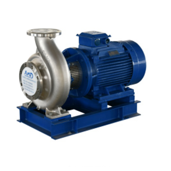
Centrifugal pumps from DAE Pumps are perfectly suited for demanding process applications. Their heavy-duty construction ensures long-lasting performance in rugged conditions. The DAE Pumps knowledge and experience building top-of-the-line pumps make our centrifugal process pumps ideal in many markets and applications.
The durable DAE Pumps centrifugal pumps provide a proven ability to handle a variety of applications in the water and wastewater industries. These reliable instruments are perfect solutions for pumping chemicals used to treat water, irrigation, fountains, and much more.
For help selecting the most efficient pump for your project, call us at (760) 821-8112 or submit a request. Find the right pump size, volume, speed that you need. Get a FREE custom pump curve to ensure the right pump.
The motor or engine on a pump is as important as the pump itself. It is the driving force that makes the pump go. DAE Pumps offer a variety of motor choices: electric, diesel, and hydraulic.
Frames and skids hold the pump and motor together to make a complete unit. The frame provides stability for the placement of the pump and motor with the intent of a permanent install or seldom movement. The DAE Pumps trailer brings mobility to centrifugal slurry pumps. The whole unit, skid included, is mounted onto a trailer for mobile accessibility. Many industries use centrifugal pumps for performing multiple applications, and they move from one location to another quite frequently. The trailer provides a tremendous advantage of being on wheels.
Centrifugal pumps come in many shapes and sizes. There are two main parts to a centrifugal pump; the pump and the motor/engine. The electric motor or a diesel engine converts the energy it creates into mechanical energy. This mechanical energy drives the pump and moves the water. The centrifugal slurry pumps pull water and other materials in through the inlet and pushes it out through the outlet/discharge.
The electric motor and diesel engine work relatively similarly. A motor consists of a fan and protective casing mounted at the back. Inside the motor is the stator. The stator holds copper coils. Concentric to this is the rotor and shaft. The rotor rotates, and as it spins, so does the pump shaft. The shaft runs the entire length of the motor and into the pump where it connects to the pump’s impeller.
There are a couple of variations to a centrifugal pump. Some models of centrifugal pumps have a separate shaft for the pump and the motor. The connection between the separated shafts is called the coupling. These coupled pumps will contain a bearing house with bearings. The pump shaft then continues into the pump casing. As it enters the casing it passes through a gland, packing, and the stuffing box, which combined to form a seal. The shaft then connects to the impeller. The impeller imparts centrifugal force onto the fluid that makes it to move liquids through a pipe or hose. The impeller is in the pump casing. The casing contains and directs the flow of water as the impeller pulls it in through the suction inlet and pushes it out through the discharge outlet.
At the center of this stator are the rotor and shaft. The rotor is affected by the rotating magnetic field and forces it to auto-rotate. The rotor connects to the shaft, which runs from the fan to the impeller. When the rotor rotates, so does the impeller. By creating the rotating magnetic field within the motor, the rotor spins the shaft and the impeller.
At the pump casing, there is a channel for water to flow along, which is called the volute. The volute spirals around the perimeter of the pump casing to the outlet. This channel increases in diameter as it makes its way to the outlet. The shaft passes through the seals and into the pump casing, where it connects to the impeller.
There are many types of impellers, but most have backward curved veins, which will either be open, semi-open, or closed. These backward-curved veins do not push the water. The curves rotate with the outer edge moving in the direction of the expanding volute. These veins will provide the fluid with a smooth path for the water to flow.
Liquid engulfs the impeller, and when it rotates, the fluid within the impeller also spins and is forced outward to the volute. As the fluid moves outwards, off of the impeller, it creates a region of low pressure that pulls more water in through the suction inlet. The fluids enter the eye of the impeller and are trapped there between the blades. As the impeller rotates, it imparts kinetic energy or velocity onto the liquid. By the time the liquid reaches the edge of the impeller, it is moving at a very high speed. This high-speed liquid flows into the volute where it hits the wall of a pump casing. This impact converts the velocity into potential energy or pressure. More fluid follows behind this developing a flow.
The thickness of the impeller and the rotational speed affects the volume flow rate of the pump and the diameter of the impeller, and the rotational speed increases the pressure it can produce.
Net Positive Suction Pressure or NPSH is associated with pump suction. At the end of this acronym are two other letters NPSHR and NPSHA. The R is the required NPSH. Each pump tests for this value. At DAE Pumps, we provide a pump operation chart with all our specs. The R-value is a warning or danger point. As the fluid enters the pump and flows into the impeller’s eye, it experiences a lot of energy due to the friction, giving a pressure drop. At certain conditions, the fluids flowing through this section can reach a boiling point. Once this happens, cavitation may occur.
The last letter in NPSHA stands for Available. The net positive suction pressure available depends on the installation of the pump and should be calculated. NPSHA takes into consideration things like insulation types, elevation, liquid temperature, liquid boiling point, much more. Available pressure should always be higher than the required value. For example, if the NPSHA is 12 for the pump requiring an NPSHR of 4 then the pump should be okay. However, a pump that required an NPSHR of 15 than the available NPSH is insufficient, and cavitation will occur.
DAE Pumps provides custom pump curves per the information you provide. Including as much information about the project allow us to best match a pump with your needs, so the centrifugal pump you get is ideal for the project.
Cavitation in pumps is the deterioration of the pump’s metal due to the overheating of water. Cavitation destroys the pump’s impeller and casing that lead to replacing parts and the pump altogether.
Water can turn from a liquid state into steam or gas and boils at around 100 degrees Celsius at sea level. However, at a higher elevation, water boils at a lower temperature because of atmospheric pressure. If this pressure is less than the vapor pressure of the liquid that is pumping, then the water can reach a boiling point. When this happens, cavitation occurs.
During cavitation, air particles within the water expand, and as they reach the boiling point, they collapse in on themselves very rapidly. As they collapse, they start to damage the impeller and pump casing. This damage removes small parts of metal from the surface, and if this keeps occurring, then it will eventually destroy the pump. Therefore, you must ensure the Available pressure is higher than the Required pressure of the pump.
DAE Pumps provides a full spectrum of centrifugal slurry pumps and accessories for completing all your tough dredging projects.We provide turnkey solutions with complete centrifugal slurry pump systems that includeslurry hoses, slurry flow meters, power units,and more.Choose from multiple sizes of slurry hoses for the transferring of materials, wireless flow meters for measuring the flow rate in gallons per minute of liquid, and power units for operation.Parts are always in stock and available for immediate shipping to anywhere in the US and the world.
Our focus on should be to consolidate and enhance the quality and repair of present products, in the meantime constantly establish new products to meet unique customers" requires for Neoprene Impeller, Slurry Mud Pump Parts, Pump Frame Plate Liner, We"re going to endeavor to maintain our fantastic track record as the very best products supplier in the planet. When you"ve got any questions or reviews, you should get in touch with with us freely.
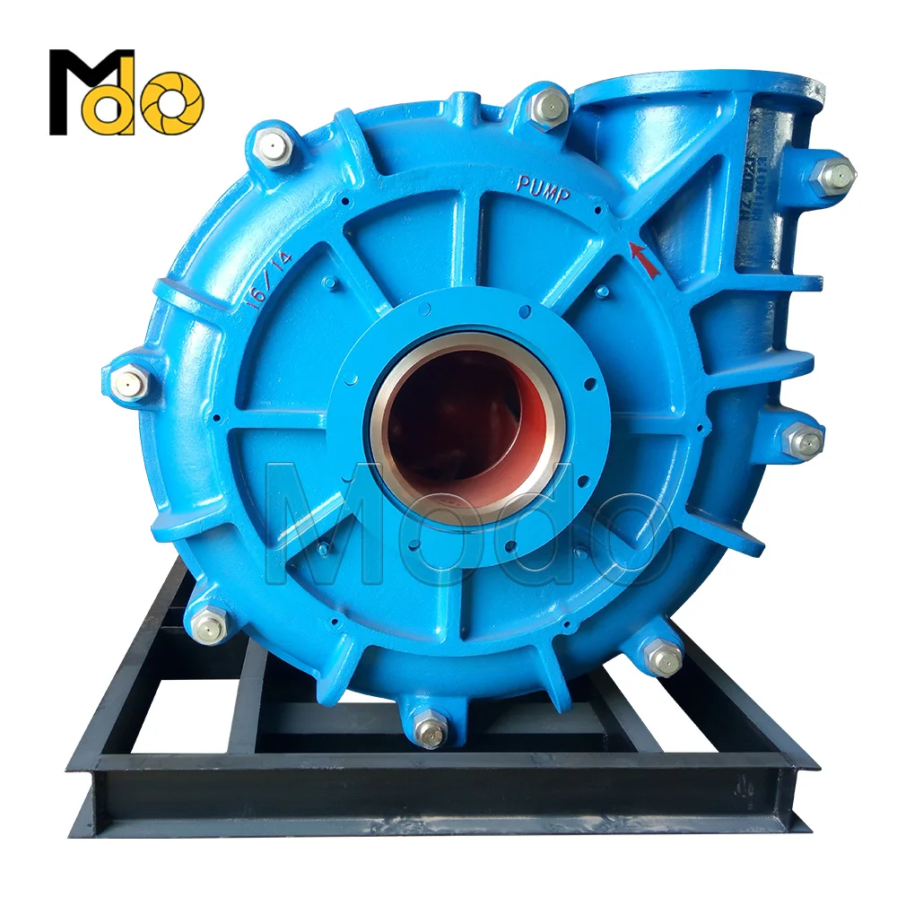
Most rubber lined slurry pumps use split volute type rubber liners, one is frame plate liner, and another is cover plate liner, this structure is designed to make replacement easy.
* YAAO® is a registered trademark and does not represent or is not in any way affiliated with Warman® of Weir Minerals Group. All names, numbers, symbols and descriptions are used for reference purpose only and do not imply that any pumps or parts listed is the product of Warman Pumps.
We believe that long time period partnership is a result of top of the range, value added services, rich expertise and personal contact for China Free sample for Slurry Pump Manufacturers - L-Type Slurry Pump Frame Plate Liner – YAAO factory and suppliers | YAAO , The product will supply to all over the world, such as: Malaysia, Eindhoven, Turkmenistan, Our technical expertise, customer-friendly service, and specialized merchandise make us/company name the first choice of customers and vendors. We"ve been looking for your inquiry. Let"s set up the cooperation right now!

A typical centrifugal pumpis constructed of a rotary pump shaft with one or more impellers attached. As the impellers rotate in sync, the pump converts enough energy to move fluids in the desired direction.
Centrifugal pumpscan be radial or axial, with radial pumps pushing energy through downstream piping and axial pumps generating asuction liftingeffect with the impellers. Either are simple enough processes, but something could go wrong. When that does, you’ll need to troubleshoot and fix the problem.
If yourcentrifugal pumpstops working as it should, is it time to replace it or call in a professional? Neither may be necessary if you can figure out the problem and solve it independently. Here are some of the most commoncentrifugal pump problemsand solutions.
Impellers rotating in the wrong direction is a common problem withcentrifugal pumps. If the impellers turn the wrong way, they could cause severe damage to the pump. When wiring power to the pump’s motor, it’s critical to verify which way the motor turns. You can “bump start” the motor to do this.
Another common problem with these types ofcentrifugal pumpsis leakage. When materials escape the pump and create a mess, this is a serious issue. Excessive temperature, corrosion, or pressure can loosen the joints and seals, allowing fluid and debris to escape.
But there may be a simple fix. Stopping your leaky pump could be as easy as tightening the fasteners surrounding the joints. In other cases, however, you may need to replace a gasket or mechanical seal.
There is probably something wrong with your pump if it takes too long to re-prime. The most common cause of a slow re-priming pump is excessive clearance, leading to inefficiency and overheating. But other possible reasons exist as well, such as a leaking gasket, a clogged recirculation port, or a worn-out volute.
Pump seizure can happen for several reasons, including foreign objects entering the pump, low flow operation, and off-design conditions. Inspect the pump for foreign objects and debris first and then check the impellers and power source.
When you begin to see the pump vibrating too much or notice usual noises coming from the device, this could signify a serious issue. Often, vibrations and noises tell you that you have failed bearings or a foreign object stuck inside the pump.
Start with the most straightforward thing first and look for debris or foreign objects. When noises and vibrations occur together, the pump could be experiencing cavitation and may need to be examined by a professional.
Debris in your pump can create havoc with many of its parts and systems. If your pump isn’t pumping or is less efficient than you want, check for a cloggedsuction pipeor debris in the impeller.
Incentrifugal pumps, overloading occurs when the driving motor draws excess current, which results in greater than normal power consumption. Pumps should start with a minimum load with discharge valves open. If the power drawn by the pump increases too much, it may ultimately lead to tripping or overloading of the motor. Some of the most common causes of pump driver overload include:
If you notice that the pump isn’t operating efficiently anymore, meaning it’s taking too long for it to pump out fluid, some of the most common causes of this problem include the following.
If yourcentrifugal pumphas become corroded, it could be due to a chemical compatibility issue. The wetted parts of a pump can be made from a variety of materials — ceramics, metals, thermoplastics, and elastomers. The resistance of these parts to various liquids, chemicals, and temperatures will vary. So you must select a pump designed with your particular application in mind.
Centrifugal pumpsshould not feel hot to the touch. When they do, this is a sign of trouble and something you want to address immediately. There may be a blockage in the suction strainer, the recirculation port, the valve, or the open-ended discharge line. The pump will be less efficient if you ignore the issue and may eventually fail.
There is a wide range ofcentrifugal pumpsavailable that will give your operation the fluid-transfer services it needs over the long term. These are excellent, low-cost solutions for most high-capacity, low-pressure situations. But if yourcentrifugal pumpisn’t operating efficiently or at all, this list of common problems may help you troubleshoot the issue.
If you cannot troubleshoot the issue with yourcentrifugal pumpor don’t feel comfortable handling it yourself, we haveresourcesto help you. If you aren’t currently experiencing any problems with yourcentrifugal pump, then it is a great time to look intopreventative maintenance to ensure issues don’t arise in the future.
When choosing a size and type of mud pump for your drilling project, there are several factors to consider. These would include not only cost and size of pump that best fits your drilling rig, but also the diameter, depth and hole conditions you are drilling through. I know that this sounds like a lot to consider, but if you are set up the right way before the job starts, you will thank me later.
Recommended practice is to maintain a minimum of 100 to 150 feet per minute of uphole velocity for drill cuttings. Larger diameter wells for irrigation, agriculture or municipalities may violate this rule, because it may not be economically feasible to pump this much mud for the job. Uphole velocity is determined by the flow rate of the mud system, diameter of the borehole and the diameter of the drill pipe. There are many tools, including handbooks, rule of thumb, slide rule calculators and now apps on your handheld device, to calculate velocity. It is always good to remember the time it takes to get the cuttings off the bottom of the well. If you are drilling at 200 feet, then a 100-foot-per-minute velocity means that it would take two minutes to get the cuttings out of the hole. This is always a good reminder of what you are drilling through and how long ago it was that you drilled it. Ground conditions and rock formations are ever changing as you go deeper. Wouldn’t it be nice if they all remained the same?
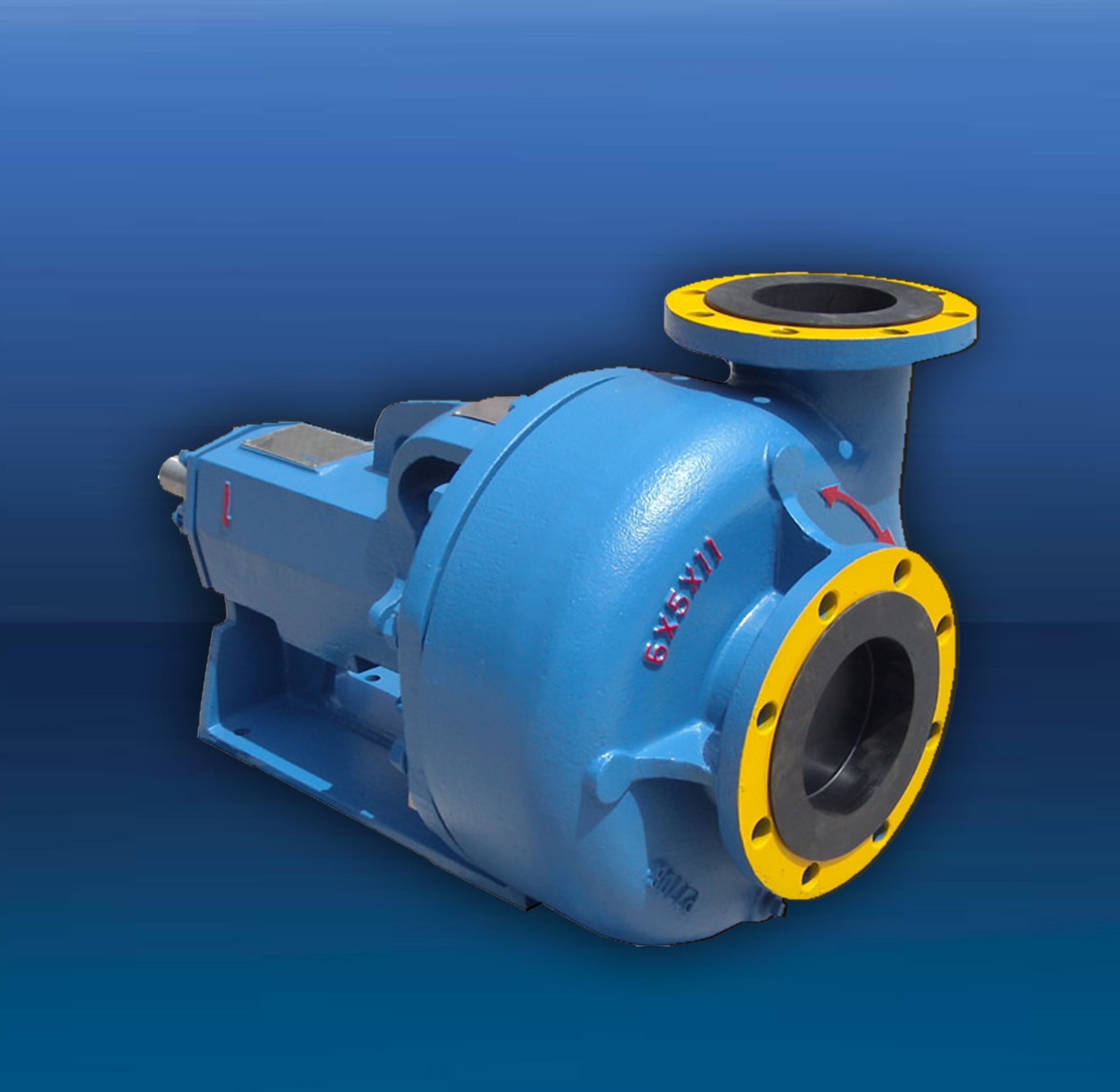
Centrifugal-style mud pumps are very popular in our industry due to their size and weight, as well as flow rate capacity for an affordable price. There are many models and brands out there, and most of them are very good value. How does a centrifugal mud pump work? The rotation of the impeller accelerates the fluid into the volute or diffuser chamber. The added energy from the acceleration increases the velocity and pressure of the fluid. These pumps are known to be very inefficient. This means that it takes more energy to increase the flow and pressure of the fluid when compared to a piston-style pump. However, you have a significant advantage in flow rates from a centrifugal pump versus a piston pump. If you are drilling deeper wells with heavier cuttings, you will be forced at some point to use a piston-style mud pump. They have much higher efficiencies in transferring the input energy into flow and pressure, therefore resulting in much higher pressure capabilities.
Piston-style mud pumps utilize a piston or plunger that travels back and forth in a chamber known as a cylinder. These pumps are also called “positive displacement” pumps because they literally push the fluid forward. This fluid builds up pressure and forces a spring-loaded valve to open and allow the fluid to escape into the discharge piping of the pump and then down the borehole. Since the expansion process is much smaller (almost insignificant) compared to a centrifugal pump, there is much lower energy loss. Plunger-style pumps can develop upwards of 15,000 psi for well treatments and hydraulic fracturing. Centrifugal pumps, in comparison, usually operate below 300 psi. If you are comparing most drilling pumps, centrifugal pumps operate from 60 to 125 psi and piston pumps operate around 150 to 300 psi. There are many exceptions and special applications for drilling, but these numbers should cover 80 percent of all equipment operating out there.
The restriction of putting a piston-style mud pump onto drilling rigs has always been the physical size and weight to provide adequate flow and pressure to your drilling fluid. Because of this, the industry needed a new solution to this age-old issue.
As the senior design engineer for Ingersoll-Rand’s Deephole Drilling Business Unit, I had the distinct pleasure of working with him and incorporating his Centerline Mud Pump into our drilling rig platforms.
In the late ’90s — and perhaps even earlier — Ingersoll-Rand had tried several times to develop a hydraulic-driven mud pump that would last an acceptable life- and duty-cycle for a well drilling contractor. With all of our resources and design wisdom, we were unable to solve this problem. Not only did Miller provide a solution, thus saving the size and weight of a typical gear-driven mud pump, he also provided a new offering — a mono-cylinder mud pump. This double-acting piston pump provided as much mud flow and pressure as a standard 5 X 6 duplex pump with incredible size and weight savings.
The true innovation was providing the well driller a solution for their mud pump requirements that was the right size and weight to integrate into both existing and new drilling rigs. Regardless of drill rig manufacturer and hydraulic system design, Centerline has provided a mud pump integration on hundreds of customer’s drilling rigs. Both mono-cylinder and duplex-cylinder pumps can fit nicely on the deck, across the frame or even be configured for under-deck mounting. This would not be possible with conventional mud pump designs.
The second generation design for the Centerline Mud Pump is expected later this year, and I believe it will be a true game changer for this industry. It also will open up the application to many other industries that require a heavier-duty cycle for a piston pump application.
Impeller types in Centrifugal Pumps vary in design depending on the fluid being handled, whether design is low or high pressure, and if the unit designed is self-priming or to handle entrained gas.
Typically, the closer that radial vanes are together, the tighter the tolerances and more enclosed impeller design, the higher the efficiency and lower the solid handling capacity due to limitations in free passage.
The solid handling capability is defined by the space between the front and rear channels in the impeller which for small units could be measured in microns.
Fluid is drawn into the impeller eye (centre) before centrifugal forces direct fluid through blades, then directed towards the side of the pump casing, and expelled through the outlet.
The impeller does not have a tip unlike other low shear designs of pumps, meaning it can transfer soft or damage prone products without breakage, such as fruit pieces as they do not pass through the impeller.
Traditionally liquid flows through the impeller before being expelled radially towards the casing outlet however this version creates a vortex within the casing enabling the passage of fibrous materials or solid particles which often do not come into contact with it. Only a small percentage of particles make contact with the rotating part, with this design also referred to as non clogging.
Predominately used for low head applications, it can be recessed within the pump casing to enable larger suspended solid passage without contact to pumped solids.
Macerator designs can have a tungsten carbide impeller rotating in conjunction with a diffuser plate and grinder macerating solids. Models may also can have an agitator installed on an extended motor shaft located below the impeller, acting as a stirrer ensuring matter at the pump suction is broken up and transferred through the pump.
This enables the unit to deliver higher pressures than a solid handling pump utilising smaller pipework making it ideal in situations where high pressures are needed and pipework size needs to be kept to as small as possible such as in long discharge lines or within a sewage pumping application when an additional bathroom may be added in a property within a basement.
3.CavitationWhen there is a lack of suction pressure, it can lead to bubbles forming within the suction, which collapse then implode on the impeller surface, eroding large areas quickly leading to failure.
4.ImbalanceAt manufacturing stage all impellers are balanced. If these are not balanced it leads to unequal radial forces and associated accelerated component wear due to heavy vibration.This directly affects the lifespan of the mechanical seal, and bearings leading to premature pump failure.
5.Water HammerWater hammer is the sudden stopping of a fluid causing momentum present in the liquid to reverse flow, travel back and forth rapidly creating vibration.This can cause impellers and casings to crack due to the forces involved.
6.LooseImpellers have the possibility of becoming loose when vibrations occur within the unit. This consequently leads to the part coming into contact with wear rings, or pump casing at speed causing destruction of the unit.
7.ResonanceWith the fitting of Variable Speed Drives assumptions can be made that a pump can be operated at any rpm. Some RPM’s can create resonance within pump parts leading to vibration.
8.FoulingFouling can reduce the free flowing path of liquids reducing efficiency. If pumps have been stood for some time growths can occur, not only within the pump but within suction pipework in marine environments known as biofowling.
This can lead to cavitation within units and If designs are chosen with closed impellers which then encounter solid particles, these can clog internal passage.
9.Turbulent FlowWhen flow is turbulent and not laminar, it can create separation of the pumped fluid occurs but it also creates the ideal conditions for cavitation to occur.
Impellers undergo trimming to enable pumps to meet specific duties. Typically units are manufactured with impellers at full size, and when used with an inverter the rotational speed can be reduced to reduce the flow and pressure to meet the required duty point. By keeping the impeller at full diameter, clearances between the rotating part and casing are kept small maintaining efficiency.
Trimming impellers is another way a pump can be made to meet a duty point, however the more material that is removed, greater internal tolerances are created within the casing reducing efficiency.
Pump affinity laws are a set of formula which can be used to determine a units performance when a change is made such as speed, or impeller diameter to the produced flow and pressure with a high degree of accuracy.
As the shaft speed or the impeller diameter is altered, the flow will change by the same amount. If the speed of a pump is reduced by 20% the flow at the same head will also decrease by 20%.
When the impeller diameter is altered or shaft speed is changed pressure changes proportional to the square of the change in shaft speed or impeller diameter. If a shafts speed increases by 10% then pressure at the same flow will increase by 21%
Wear rings sit either side of the impeller to act as sacrificial parts to prevent casing wear and maintain efficiency within the casing. A doubling of wear ring clearances can lead to NPSH increasing by as much as 50%.

Cavitation is an undesirable condition that reduces pump efficiency and leads to excessive wear and damage to pump components. Factors that can contribute to cavitation, such as fluid velocity and pressure, can sometimes be attributed to an inadequate mud system design and/or the diminishing performance of the mud pump’s feed system.
When a mud pump has entered full cavitation, rig crews and field service technicians will see the equipment shaking and hear the pump “knocking,” which typically sounds like marbles and stones being thrown around inside the equipment. However, the process of cavitation starts long before audible signs reveal themselves – hence the name “the silent killer.”
Mild cavitation begins to occur when the mud pump is starved for fluid. While the pump itself may not be making noise, damage is still being done to the internal components of the fluid end. In the early stages, cavitation can damage a pump’s module, piston and valve assembly.
The imperceptible but intense shock waves generated by cavitation travel directly from the fluid end to the pump’s power end, causing premature vibrational damage to the crosshead slides. The vibrations are then passed onto the shaft, bull gear and into the main bearings.
If not corrected, the vibrations caused by cavitation will work their way directly to critical power end components, which will result in the premature failure of the mud pump. A busted mud pump means expensive downtime and repair costs.
To stop cavitation before it starts, install and tune high-speed pressure sensors on the mud suction line set to sound an alarm if the pressure falls below 30 psi.
Although the pump may not be knocking loudly when cavitation first presents, regular inspections by a properly trained field technician may be able to detect moderate vibrations and slight knocking sounds.
Gardner Denver offers Pump University, a mobile classroom that travels to facilities and/or drilling rigs and trains rig crews on best practices for pumping equipment maintenance.
Severe cavitation will drastically decrease module life and will eventually lead to catastrophic pump failure. Along with downtime and repair costs, the failure of the drilling pump can also cause damage to the suction and discharge piping.
When a mud pump has entered full cavitation, rig crews and field service technicians will see the equipment shaking and hear the pump ‘knocking’… However, the process of cavitation starts long before audible signs reveal themselves – hence the name ‘the silent killer.’In 2017, a leading North American drilling contractor was encountering chronic mud system issues on multiple rigs. The contractor engaged in more than 25 premature module washes in one year and suffered a major power-end failure.
Gardner Denver’s engineering team spent time on the contractor’s rigs, observing the pumps during operation and surveying the mud system’s design and configuration.
The engineering team discovered that the suction systems were undersized, feed lines were too small and there was no dampening on the suction side of the pump.
Following the implementation of these recommendations, the contractor saw significant performance improvements from the drilling pumps. Consumables life was extended significantly, and module washes were reduced by nearly 85%.
Although pump age does not affect its susceptibility to cavitation, the age of the rig can. An older rig’s mud systems may not be equipped for the way pumps are run today – at maximum horsepower.

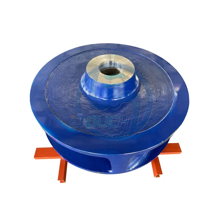
You can use impeller for mud pump to pump liquids in different fields such as the pharmaceutical sector, perfume productions, dairy production, canning sector, and a lot more. You should select the centrifugal pump impeller depending on the engine power. You also use motor impellers as distributors.
Pool impellers are ideal for pumping emulsions, as they can contain the small particles found in liquids. The impeller blade is connected to the adapter shaft and has a separate hole for liquid suction. The axial flow impeller is another variant that you can find in our collection of wholesale impeller for mud pump. This type of impeller provides you with top to bottom circulation, and with most energy being converted into a flow.
The available options and applications of impeller for mud pump are countless. You can select jet impellers to equip your water transport units (e.g., jet skis) with high-performance water pumping engines. Or you can go for flexible impeller pumps that can be used under different conditions and environments.
Our selection also includes solutions for people wanting to clean their pool with efficiency and less effort. The pump impellers for pool cleaning are made of sturdy materials which provides them with waterproof and wear resistance capabilities. No matter what you are searching for, you will find the right product that meets your needs at Alibaba.com!
An impeller or impellorrotor used to increase the pressure and flow of a fluid. It is the opposite of a turbine, which extracts energy from, and reduces the pressure of, a flowing fluid.
An impeller is a rotating component of a centrifugal pump that accelerates fluid outward from the center of rotation, thus transferring energy from the motor that drives the pump to the fluid being pumped.fluid radially, and a splined, keyed, or threaded bore to accept a drive shaft.
It can be cheaper to cast an impeller and its spindle as one piece, rather than separately. This combination is sometimes referred to simply as the "rotor."
An open impeller has a hub with attached vanes and is mounted on a shaft. The vanes do not have a wall, making open impellers slightly weaker than closed or semi-closed impellers. However, as the side plate is not fixed to the inlet side of the vane, the blade stresses are significantly lower.clearance between vanes and pump volute or back plate prevent most of fluid from flowing back. Wear on the bowl and edge of vane can be compensated by adjusting the clearance to maintain efficiency over time. specific speed. Open impellers are usually faster and easier to maintain. For small pumps and those dealing with suspended solids, open impellers are generally used.
A semi-closed impeller has an additional back wall, giving it more strength. These impellers can pass mixed solid-liquid mixtures at the cost of reduced efficiency.
The construction of closed impellers includes additional back and front walls on both sides of vanes that enhances its strength. This also reduces the thrust load on the shaft, increasing bearing life and reliability and reducing shafting cost. However, this more complicated design, including the use of additional wear rings, makes closed impellers more difficult to manufacture and more expensive than open impellers. A closed impeller"s efficiency decreases as wear ring clearance increases with use. However, adjustment of impeller bowl clearance does not affect the wear on vanes as critically as open impeller.
The main part of a centrifugal compressor is the impeller. An open impeller has no cover, therefore it can work at higher speeds. A compressor with a covered impeller can have more stages than one that has an open impeller.
Because impellers do not have large blades to turn, they can spin at much higher speeds than propellers. The water forced through the impeller is channeled by the housing, creating a water jet that propels the vessel forward. The housing is normally tapered into a nozzle to increase the speed of the water, which also creates a Venturi effect in which low pressure behind the impeller pulls more water towards the blades, tending to increase the speed.
To work efficiently, there must be a close fit between the impeller and the housing. The housing is normally fitted with a replaceable wear ring which tends to wear as sand or other particles are thrown against the housing side by the impeller.
Impellers in agitated tanks are used to mix fluids or slurry in the tank. This can be used to combine materials in the form of solids, liquids and gas. Mixing the fluids in a tank is very important if there are gradients in conditions such as temperature or concentration.
Radial flow impellers impose essentially shear stress to the fluid, and are used, for example, to mix immiscible liquids or in general when there is a deformable interface to break. Another application of radial flow impellers is the mixing of very viscous fluids.
Axial flow impellers impose essentially bulk motion and are used on homogenization processes, in which increased fluid volumetric flow rate is important.
Fire services in the United Kingdom and many countries of the Commonwealth use a stylized depiction of an impeller as a rank badge. Officers wear one or more on their epaulettes or the collar of their firefighting uniform as an equivalent to the "pips" worn by the army and police.
Air pumps, such as the roots blower, use meshing impellers to move air through a system. Applications include blast furnaces, ventilation systems, and superchargers for internal combustion engines.
Lin, Peng; Liu, Meiqing; Zhao, Wensheng; Liu, Zhiyong; Wu, Yuanwei; Xue, Fei; Zhang, Yipeng (2017). "Influence of tip clearance on the performance of a screw axial-flow pump". Advances in Mechanical Engineering. 9 (6). doi:S2CID 117627953.
Chou, N. K.; Wang, S. S.; Chu, S. H.; Chen, Y. S.; Lin, Y. H.; Chang, C. J.; Shyu, J. J.; Jan, G. J. (2001). "Physiologic analysis of cardiac cycle in an implantable impeller centrifugal left ventricular assist device". Artificial Organs. 25 (8): 613–6. doi:10.1046/j.1525-1594.2001.025008613.x. PMID 11531711.


 8613371530291