
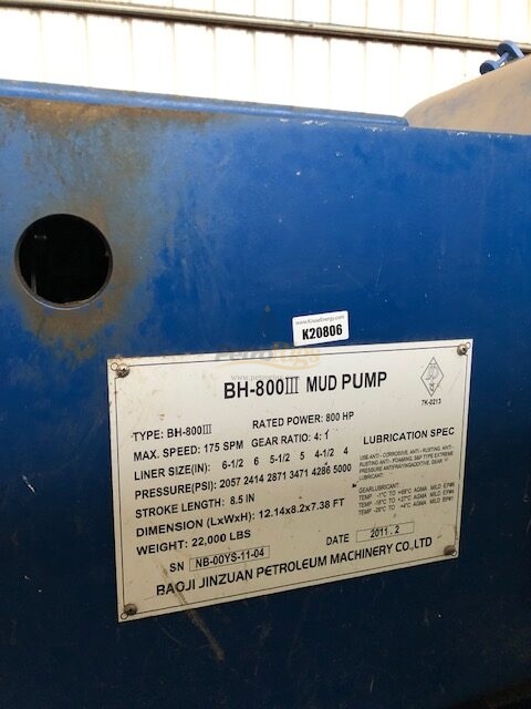
mud pump liner size and stroke length supplier

Rig pump output, normally in volume per stroke, of mud pumps on the rig is one of important figures that we really need to know because we will use pump out put figures to calculate many parameters such as bottom up strokes, wash out depth, tracking drilling fluid, etc. In this post, you will learn how to calculate pump out put for triplex pump and duplex pump in bothOilfield and Metric Unit.

This website is using a security service to protect itself from online attacks. The action you just performed triggered the security solution. There are several actions that could trigger this block including submitting a certain word or phrase, a SQL command or malformed data.
F 500 mud pump for oil drilling have features of solid and compact structure, small volume, good and reliable performance. It can meet the drilling requirements such as high pressure and big displacements whether in land drilling or off-shore drilling.
F 500 mud pumps have a longer stroke and can be operated at a lower stroke, thus improved the water supplying performance effectively and extended the lifetime of mud pump fluid end parts greatly.
This website is using a security service to protect itself from online attacks. The action you just performed triggered the security solution. There are several actions that could trigger this block including submitting a certain word or phrase, a SQL command or malformed data.

Oil and Gas drilling process - Pupm output for Triplex and Duplex pumpsTriplex Pump Formula 1 PO, bbl/stk = 0.000243 x ( in) E.xample: Determine the pump output, bbl/stk, at 100% efficiency for a 7" by 12". triplex pump: PO @ 100%,= 0.000243 x 7 x12 PO @ 100% = 0.142884bbl/stk Adjust the pump output for 95% efficiency: Decimal equivalent = 95 + 100 = 0.95 PO @ 95% = 0.142884bbl/stk x 0.95 PO @ 95% = 0.13574bbl/stk Formula 2 PO, gpm = [3(D x 0.7854)S]0.00411 x SPM where D = liner diameter, in. S = stroke length, in. SPM = strokes per minute Determine the pump output, gpm, for a 7" by 12". triplex pump at 80 strokes per minute: PO, gpm = [3(7 x 0.7854) 1210.00411 x 80 PO, gpm = 1385.4456 x 0.00411 x 80 PO = 455.5 gpm
Example:Duplex Pump Formula 1 0.000324 x (liner diameter, in) x ( stroke lengh, in) = ________ bbl/stk -0.000162 x (rod diameter, in) x ( stroke lengh, in) = ________ bbl/stk Pump out put @ 100% eff = ________bbl/stk Example: Determine the output, bbl/stk, of a 5 1/2" by 14" duplex pump at 100% efficiency. Rod diameter = 2.0": 0.000324 x 5.5 x 14 = 0.137214bbl/stk -0.000162 x 2.0 x 14 = 0.009072bbl/stk Pump output @ 100% eff. = 0.128142bbl/stk Adjust pump output for 85% efficiency: Decimal equivalent = 85 100 = 0.85 PO@85%)= 0.128142bbl/stk x 0.85 PO@ 85% = 0.10892bbl/stk Formula 2
PO. bbl/stk = 0.000162 x S[2(D) - d] where S = stroke length, in. D = liner diameter, in. d = rod diameter, in. Example: Determine the output, bbl/stk, of a 5 1/2". by 14". duplex pump @ 100% efficiency. Rod diameter = 2.0in.: PO@100%=0.000162 x 14 x [ 2 (5.5) - 2 ] PO @ 100%)= 0.000162 x 14 x 56.5 PO@ 100%)= 0.128142bbl/stk Adjust pump output for 85% efficiency: PO@85%,= 0.128142bb/stkx 0.85 PO@8.5%= 0.10892bbl/stk Metric calculation Pump output, liter/min = pump output. liter/stk x pump speed, spm. S.I. units calculation Pump output, m/min = pump output, liter/stk x pump speed, spm. Mud Pumps Mud pumps drive the mud around the drilling system. Depending on liner size availability they can be set up to provide high pressure and low flow rate, or low pressure and high flow rate. Analysis of the application and running the Drill Bits hydraulics program will indicate which liners to recommend. Finding the specification of the mud pumps allows flow rate to be calculated from pump stroke rate, SPM. Information requiredo Pump manufacturer o Number of pumps o Liner size and gallons per revolution Weight As a drill bit cutting structure wears more weight will be required to achieve the same RoP in a homogenous formation. PDC wear flats, worn inserts and worn milled tooth teeth will make the bit drill less efficiently. Increase weight in increments of 2,000lbs approx. In general, weight should be applied before excessive rotary speed so that the cutting structure maintains a significant depth of cut to stabilise the bit and prevent whirl. If downhole weight measurements are available they can be used in combination with surface measurements to gain a more accurate representation of what is happening in the well bore.

Kverneland, Hege, Kyllingstad, Åge, and Magne Moe. "Development and Performance Testing of the Hex Mud Pump." Paper presented at the SPE/IADC Drilling Conference, Amsterdam, Netherlands, February 2003. doi: https://doi.org/10.2118/79831-MS
3 pumps in the oil, gas, and water drilling industries. The process ~ is carried out by performing a number of manufacturing steps during which a worn cylinder liner is reformed and improved to produce 6 a usable liner which provides an extended period of service. I
9 IIn the oil and gas drilling rigs, these are referred to as "mud pumps" and are generally of two types: (a) a duplex pump which 11 has two reciprocating pistons which force fluid into the discharge 12 line and (b) a triplex reciprocating pump in which three pistons 13 act to force fluid into the discharge line. "Multiplex pumps"is 14 a generic term which is occasionally used to include triplex pumps ~~ and those having up to six cylinders. These fluid pumps can be 16 single acting in which fluid is discharged on alternate strokes 17 or double acting in which each stroke discharges fluid.
18 ; The fluid pumps involved in this invention are of the .1 i 19 horizontal reciprocating type in which one end is termed the l~fluid end and the other end is designated the power end. The fluid 21 end consists of a pump housing in which are fitted a number of 22 cylinders corresponding to the number of pistons which are operated 23 within the pump. The power end of the pumps contains a power 24 ~ source and connecting rods designed for supplying reciprocal driving force.
26 ` Each pump cylinder contains a liner within which the 27 piston operates over its power stroke. Other fluid end pump parts 28 are rods, valve pots, seats, gaskets and piston rubbers. The liner ~,~
2 The cylinder liner is subject ta high wear rates due to a 3 large number oE factors such as the geological formation being
4 drilled, the solids content in the fluid, the abrasive properties of the solids, and pH of the fluid, the pump pressure, strokes per 6 minute of the piston, and the materials used in the various pump 7 parts.
8 ~ The pump cylinder liner in a duplex pump typically has an 9 average life of 1200 to 1500 pump hours, that is about 90 to 100 days, andthe average life ofthe cylinder ~ners in the triplex i~ " ll;pumps is about 500 to 900 hours or about 50 to 60 days of service 12 life at a normal duty cycle. The usual maintenance practice for 13 fluid pumps is then to replace the fluid end expendable parts at 14 the end oE their respective service lives. This practice, however, has grown relatively expensive since about 50% of -the total mainten-16 ance cost is in the cylinder liners which range in price from about 17$400 to ~1~00. Thus, replacement of liners in a large sized tri-18 plex pump could run three times the larger amount. The average 19 liner costs are; however, less since these are estimated to be 20i$750 for each duplex liner and $650 for a triple~ liner.
21About 90% of the liners sold in the U.S. at the present 22 ltime are known as "premium liners" in which a alloy steel outer 23 ~hull has an inner surface layer of a wear resistant chromium 24 alloy. Such hard surfaced cylinder liners are priced in the mid to upper end of the above price range. Other "nonpremium" liners 26 are fabricated from Mild steel and have only a heat hardened inside 27 diameter, I.~., surface. The replacement of the cylinder liners 28at the end of each 50 to 100 days of the service cycle results 29 in hi~h pump maintenance costs.
30The liner replacement market in the IJ.S. and Canada is 31about 110,000 to 120,000 liners per year. Statistical maintenance _ _ . .. _ ... . _ . ~_ .... _ ._ _ _ .. .. . . . ._ .. ..... .. ,_ . . . .. . . . .. . .. . . .
~97~0 1 data has shown that the average number of liner chan~es per year 2 for a triplex pump is 7.2. At this level of use 23 liners/year 3 are required for a cost of approximately $15,000.00 while the addi-4 tional maintenance charges amount to another $15,000.00. Part of the high liner replacement cost is due to the chromium content in 6 the scrapped premium liners which is not recovered. Each of the 7 worn liners contains about 12 to 15 pounds of chromium. The wear 8 resistant chromium alloy is about 28% chromium with other elements 9 ~being magnesium, vanadium, and molybdenum~ The chromium alloy ", inner surface has a hardness of 62 to 65 on the Rockwell C scale 11 and is a wear and corrosion resistant metal surface which is heat 12 treated.
13 The premium pump cylinder liners with the chromium alloy 14 inner surfaces are manufactured by the three principal processes of (a) bi-metal centrifugal casting; (b) shrinking a wear-resistant 16 chromium iron or stainless steel alloy sleeve into the liner and 17 ,~. (c) chrome alloy platlng the inner surface of an alloy steel liner 18 hull. Other seldom used methods of producing premium liners are 19 those in which hard surface treatments are used for the steel hulls. These consist of coating the inner surface of the 21 liners with a hard metal using such techniques as plasma arc 22 spray or powdered metallurgy surfacing. These treatments produce 23 a wear-resistant layer of about 0.020 inch in thickness with an 24 additional thickness of an impregnation layer within the hull metal. The alloy steel liner hulls used for these manufacturing 26 processes are usually fabricated from 4130 to 4150 steel alloy.
~ An interesting property of the bi-metal cast and sleeve 31 liners which are both centrifugally cast is that the chromium alloy ., . _ . _ _ _ , _ _ . .. _ . . . . . . , ... . . . _ _ . .. . ....... . ... . . . .
1 is believed to be more dense and of a composition closer to the 2 theoretical specifications at the cast interface. This results 3 in the metal just inward toward the Iineraxis from the interface 4 area being even more wear resistant than the inner-most I.D.
6 The pump liner is designed to fit into the cylinder which 7 is formed in the fluid end housing of the pump and is retained 8 in the housing by a liner cage and retainer arrangement. The 9 reciprocating piston consists of a metal piston core having one or more flanged hubs and a piston rubber which is retained in 11 the gap between the flanges. The outside surface of the piston 12 rubber contacts the inner surface of the liner. Various types of 13 wear occur on the liner and the piston body. Streaking of the 14 liner bore and the piston rubbers is generally caused by aggre-gate, sand or other abrasive or foreign materials in the drilling 16 1uid. A pitted liner indicates corrosive conditions, usually 17 ~- Eound for acidity levels below 7.2. pH. A concentration of wear 18 on one side of the piston or liner can occur if various working 19 conditions such as loose cross head slides, worn pump bores, snuffing boxes and junk rings misalignment and unequal tightening 21 of the liner rod packing have occurred. Pump failure is generally 22 ,indicated by e~cessive clearance between the piston flan~e and 23 the liner wall.
24 The permissible clearance prior to replacement of the fluid end expendable parts depends upon the operating pressure. In 26 low pressure service (less than 850 psi) the total clearance may 27 be 3/32 inch or more. At medium to high pressure (850 psi to 28 1600 psi) a 1/16 inch clearance is regarded as the limit. At 29 higher operating pressures of from 1600 psi to 3200 psi a clearance of 0.04 inch is considered to indicate a "worn out" piston and/or 31 liner. At medium to high pressures the indication of normai wear a 7~1 1 in a duplex pump is between 0.06 to 0.08 inches over nominal I.D.
2 and in a triplex liner isO.G35 to 0.06 over nominal. The clearance 3 dimensionmust be taken in the center of the liner since the 4 wear occurs in the mid-portion rather than at the ends of the liners.
7 As the piston fails, there is high velocity fluid slippage 8 between the piston flange and theliner bore. With a slow failing 9 ;of the piston or if a failed piston is allowed to operate in the pump, this jetting fluid will cause wash cut damage to the piston 11 flange and liner bore and the dragging of the piston flange in the 12 bore at 180 from the wash cut. The pump efficiency and the length 13 of service life rapidly decrease with increasing piston flanges-14 to-liner clearance. For example, if the clearance is 0.040 at 3000 psi, a set of replacement rubbers can be expected to last 16 only 50 percent as ].ong as they would on a new piston in a new 17 ~ liner with a clearance of 0.010 inch.
18 The wearing of the piston and the liner can not be eliri~inated 19 due to the abrasive nature of the fluids, the corrosive properties of the same, and the high operating pressure utilized in fluid 21 pumps in the drilling industry. The required replacement of the 22 jcylinder liners results in a continual high cost of operation for 23 these fluid pumps.
24 U.S. Patent No. 2,163,885 to ~acClatchie et al describes fluid pump liners and a method of fabricating the liners in 26 which flanges are joined to cylindrical pipe sleeves. There 27 is no disclosure of removing the worn liners from the fluid pumps 28 in order to remanufacture the sameO Rather the worn liners are 29 simply replaced. This patent does not therefore describe a process for remanufacturing and thereby increasing the working life 31 of a cylinder liner.
1 U.S. Patents 2,412,587 and 2,435,837 both to Larson are 2 directed to increasing the inner diameter (I.D.) of master and 3 wheel cylinders and then inserting a tubular sleeve in order to 4 produce the original I. n. dimension. There is no disclosure in this patent of remanufacturing a removable liner for the brake 6 system cylinder.
7 It is known from U.S. Patent No. 1,842,441 to Yount to 8 rebore engine block cylinders and insert cylinder sleeves or 9 liners and to then bore the new liners to the desired size for the piston to be installed. There is no use of an extracted 11 cylinder liner in this process.
12 U.S. Patent No~ 2,686,091 to Young describes various 13 methods of making pump liners using concentric sleeves, the inner 14 one oE which is usually hardened for greater resistance to wear and for longer life. There is no mention in this patent of re-16 manufacturing the liners by reboring or grinding.
17 Other U.S. Patents in this general art are: 2,133,403 to 18 Rubin; 2,832,653 to Wilson; 3,220,101 to Roy; 3,238,604 to Reinharz, 19 4,153,983 to Stockton and 4,227,292 to Kipling. The latter of ~these patents describes a process for remanufacturing a brake 21 master cylinder in which the interior bore of -the cylinder housing 22 is enlarged and a sleeve pressed therein which is subsequently 23 honed to a smooth finish. The sleeve is not honed outside of the 24 brake cylinder and the various process steps preclude such a step.
These patents do not describe remanufacturing processes wherein 26 worn pump cylinder liners are extracted from pump housing and 27 thereafter remanufactured in a manner which allows increasing 2~ of the working life of the cylinder liner.
29 It has been previously known during an earlier period when nonpremium mild steel liners were extensively used in mud pumps _ _ _ . _ . _ _ . _ _ _ .. _ _ _ . ~ . _ . , . . . _ . . .. . , .. . _ . . . ~ . , . _ . _ .. . . _ .. .
1 that the liners were sometimes removed fxom the pumps and bored 2 out to the next commercially available piston size. Such metal 3 boring and reuse of liners is not posslble and to applicant"s 4 knowledge has never been practiced with the currently used pre~lium liners because the wear-resistant metal alloy inner layer 6 in such liners is so hard that destruction of the liner and/or 7 the bore tool would occur.
8 ~, The present invention providesa process of remanufacturing 9 pump cylinder liners used in drilling fluid pumps in order to extend the working life of the liners and thus reduce operating 11 and maintenance costs. New pump liners are manufactured with bores~
5" 5.000 to 5.010 26 1~ The outer diameters of the liners are established by the 27 design of the partlcular pump and vary between the triplex and 28 duplex pump types. The liner cage and retainers also vary 29 depending upon the horse power of the pump, the length of the stroke and other design features.
1 a hard metal alloy inner layer from a pump cylinder and removing 2 portions of the interior metal surface from the liner so as to 3 form a enlarged dlameter, accurately dimensioned cylindrical surface 4 therein. An enlarged diameter,specially manufactured piston is then supplied for use in the remanufactured liner. Prior to
9 be cleaned by a number of procedures and the outer diameter can be checked, and if necessary, resurfaced to restore the original 11 outer surface dimensions.
12 The metal removing step is carried out by honing or by 13 internally grinding the liner to produce an enlarged cylindrical 14 interior surface. Honing is preferred since grinding has been found to require longer preparation time for the wear-resistant 16 hard metal inner surface layer of the liners. Prior to and during 17 -~ the metal removing step the liner axis is aligned with and clamped 18 with respect to a honing or grinding apparatus. The amount of 19 metal removed is sufficient to eliminate the center-to-end wear curvature in the liner. It is preferred to remove sufficient 21 material so that the enlarged diameter is 0.100 inch over the 22 original nominal size of the liner as employed in the fluid pump 23 prior to the extraction of the liner.
24 The remanufactured liner is then supplied for use in a fluid pump with a specially sized piston. The removal of only 26 OolO0 inch from the I.~. permits multiple remanufacturing cycles 27 in order to extend the working life of the same liner in accordance 28 with the invention hereof. Two or more such multiple remanufactur-29 ing cycles can be safely carried out on the pump cylinder liners dicclosed herein. In the cases of the chrome plated and the hard 1 coating treated liners intermediate plating and coating steps are 2 performed during the successive remanufacturing cycles. The 3 liners manufactured with shrunk-in sleeves and by bi~metal 4 casting are preferably remanufactured according to the present invention by successive metal removal cycles.
6 The present remanufacturing process for producing pump 7 cylinder liners reduces drilling fluid pump maintenance costs 8 to about 75% of the costs when the liners are only replaced 9 when worn to the limit of usefulness~ This amounts to a savings of about $250 to $300 per liner reinstalled. The process saves 11 scarce chromium all of which is imported into the U.S. and saves 12 the energy expended in the original manufacture of new liners 13 from the ore reduction through the va~ious finishing steps.
14 The remanufacturing process uses as one of its input factors a worn liner which is often in the correct general form 16 but which is regarded as a disposable fluid end component in the . ~
18 It is therefore an object of the present invention to 19 provide a process of remanufacturing and thus increasing the working life of a cylinder liner which is then positioned for 21 use in a drilling fluid pump.
22 ~nother object of the present invention is to provide a 23 process of remanufacturing a worn pump cylinder liner in which 24 the internal, worn portions are eliminated by the removal of about 0.100 inch of metal based on the nominal diameter size of the 26 liner prior to the wearing action.
27 Yet another object of the present invention is to provide 28 a process as above described wherein the extent of wear in the 29 liner can be checked prior to extracting the liner from the pump _g_ ~ "~
`" ~LZ~97 l and wherein the surface condition of the liner can be evaluated 2 prior to the removal of worn portions of metal from the interior 3 surface in order to form an enlarged diameter interior surface.
4 Another object is to provide a process of refitting a drilling fluid pump with a remanufactured liner in which a worn 6 pump liner is extracted from a pump cylinder and the I.D. enlarged 7 to eliminate the worn areas.
8 Yet another object is to provide a process for making 9 an improved pump liner wherein wear-resistant surface metal is removed fro~ the I.D. of a worn liner to uncover and present a ll more dense and hence more wear-resistant metal surface for contact 12 by the pump piston.
13 Specific preferred embodiments of the invention will be 14 described below with reference to the appended drawing figures by which the described and claimed process will be more readily 16 ,~ understood.
22 Figure 3 shows a cut-away cross-sectional view of a worn 23 pump liner i~w}1ici1the hard ~etal inner layer hasbeen accentuated;and 24 Figure ~ shows the worn pump liner of Figure 3 aligned with a honing apparatus for removal of metal from the interior surface 26 in order to form an enlarged diameter cylindrical surface therein.
1 acting duplex pump 10 which consists of a fluid end pump housing 2 12 having a first cylinder 14 and a second cylinder 16 formed there-3 in. Each of the cylinders contains a cylinder liner 18 and 20, 4 respectively. The cylinder liners are retained by cages 22 and 24 respectively which engage retaining rings 26 and 28.
6 Pistons 30 and 32 are reciprocated by piston rods 34 and 7 36 through power delivered from the power end 38. In operation, 8 the pistons reciprocate within the inner surfaces of the cylinder 9 liners 18 and 20 and thus cause theliners to wear. The wear is not uniformly distributed across the entire length of the 11 inner diameter surface but rather is concentrated in the mid-12 portion of the liner as will be hereinafter further detailed. In 13 the double-acting pump illustrated, fluid suction valve pots 14 40 and 44 and discharge valve pots 42 and 46 are located at respect-ive ends of each cylinder liner 20. In this construction each 16 stroke of the piston 32 causes fluid to exit from either of the 17 -~ valve pots 42 or 46. In the position shown, the next stroke of 18 the piston will cause fluid to flow through the discharge pot:
19 valve 46. At the same time, the suction created by piston 32 as it moves through the llner 20 will cause fluid to be taken 21 in through suction valve pot 40. The valve pots 42 and 46 are 22 located above the cylinder 16 while the suction valve pots 40 23 and ~4 are positioned at the side of the cylinder 16. Correspond-24 ing suction valve pots 48 and 50 are shown for the second cylinder 14 but the coating discharge pots associated with these two 26 suction pots have been removed in the cut-away illustration.
27 Piston 30 operates in the same manner as previously des-28 cribed with respect to piston 32. An intake line 52 is shown 29 mounted in the bottom portion of the pump housing 12 for communi-cation with the suction valve pots 40, 44, 48 and 50.
1 The two cylinders 14 and 16 are constructed with cylinder 2 heads 54 and 56, r~spectively, which removably retain cylinder 3 head covers 58 and 60 as well as the liner cages 22 and 24. A
6 Liner packings 70 and 72 in the form of ring packing glands are 7 provided between the cages 22 and 24 and the retaining rings 8 26 and 28. The reciprocating rods 34 and 36 move through stuffing 9 boxes 74 and 76 which are suitably equipped with junk rings, packing and gland nut fittings.
11 . As shown for valve pot 42 the valve pots 40, 42, 44 and 46 12 consist of a valve cover 78, a valve seat deck 80, a valve spring 13 82 and a valve 84. As seen in valve pots 48 and 50, valve 14 guides 86 and 88 are uniformly provided for each of the valves.
The piston 30 is formed of a cylindrical metal core 90 16 retained on the end of piston rod 34 by a retainer bolt 92. Piston 17 .~- rubbers 94 and 96 are shown retained between flanges 98, 100, 102 18 and 104.
19 According to the process of the present invention, the condition o~ wear on the interior surfaces of liners 18 and 20 21 is inspected by first interrupting the power supply 38 and then 22 withdrawing the pistons 30 and 32 toward the power end 38. The 23 cylinder heads 54 and 56, the cylinder head covers 58 and 60, 24 and the liner cages 22 and 24 are also removed in order to insert a measuring micrometer into the liner while it is still retained 26 in the pump housing 12. Accurate measurement of the. extent of 27 wear and inspection for wear grooves, streaking of the liner bore 28 and washed cut damage can be carried out in this manner at a low 29 service cost level.
4 2. The procured liners are cleaned on both of the inner and outer surfaces by one or a combination of (a) 6 shot blasting with pellets, (b) sand blasting, and/or 7 - (c) cleaning with a solvent.
8 3. The inside diameter of the liners is then evaluated g to determine whether or not a sufficient thickness l of the hard surface alloy metal exists to permit 11 enlargement of the I.D. during the formation of 12 a reformed cylindrical inner surface.
13 ~ 4. The extent of wear on the outer surface of the liners 14 18 and 20 is inspected to determine whether or not the degree of wear in the packing areas, flanges, 16 ` or ends of the liner will interfer with the sub-17 sequent steps in the remanufacturing method.
18 5. If the outer surfaces are sufficiently worn or out of 19 dimensional specification, these surfaces can be built up with weld, spray metal, or cold metal applications 21 while internally cooling the liner which has an 22 intact inner hard metal alloy sleeve. The liner is 23 subsequently machined to reproduce the manufacturer"s 24 external liner specifications prior to enlarging the inner diameter. An engine lathe or a turret lathe 26 can be used for this machining step. In this machin-27 ing, internal chuck jaws can be employed for holding 28 the liners since these liners will be chucked on the 29 outer end portions of the I.D. where no piston wear .. ... .... .. . ..
1 has occurred. In this manner, any build-up of 2 metal and subsequent machining will be concentric 3 with the original bore and the O.D. of the liner.
4 6. Prior to and during the removal of metal from the S outer or the inner surface the liner axis is aligned 6 with the working a~is o~ a surface metal removal 7 device.
8 ~ 7. Portions of the interior hard metal surface layer 9 ~ are then removed to form an accurately dimensioned c~lindrical I.D. surface. This step is carried out 11 by honing and/or internal grinding in which the 12 liner is centered and held or clamped on the honing 13 ~ or grindin~ machine by adapter flanges which are 14 E)ressed against the two ends of the liner. The centering is carried out by aliyning the axes of 16 the liner ~nd the metal removal head of the machine.
17 ` ~letal is removed on the I.D. of the liner in order 18 to obtain an I.D. of +0.100 inch over the nominal 19 size of the original liner, that is, +0.050 inch is removed from the cylindrical wall surface.
21 If this increase in I~D. is insufficient to clean 22 out any wear grooves and the central wear zone in the 23 liner, additional material can be removed. This 24 step is carried out by good machining practices to obtain a ma~imum of 16 rms finish.
26 8. In this process, the American Petroleum Institute 27 (API) specifications permit a 0.010 inch tolerance 28 on the I.D. of the liner and the piston. Hence, 29 after the liner is honed or grounded to the enlarged size it is rechecked to ma~e sure the I.D. is within ~.
specifications between +0.100 to +0~110 inch over the original nominal size and to assure that the O.D. is concentric with the I.D. Any additional removal of metal from the outer surface can occur following this step.
9. The liner is then painted, crated, and supplied with the proper sized piston so that a nominal sized piston matching the original liner will not be used by mistake.
The piston hub is sized at -0.005 inch under the enlarged diameter. Thus an enlarged piston designed for 5.600 inches has an upper hub size of 5.595 inches which is the largest diameter of the metal parts of -the piston.
Enlarged diameter pistons to fit the remanufac-tured liners can be produced by known manufacturing pro-cesses. These pistons will be sized from +0.100 to +0.110 inch over the nominal size pistons. These specially sized pistons can be packed with the remanufactured liner. The removal of only +0.100 inch of material from the inner surface allows multiple remanufacturing cycles with the same liner as above stated.
Of this preferred process, steps 1 and 7 are required, in principal, -to effect remanufacturing and sub-sequent use of the liner. The remaining steps are desirable according to the field practice.
1 I.D. prior to the removal step. Metal was then honed out to 2 produce a I.D. of 6.603 and 6.602 inches which was within 0.004 3 inch tolerance of being concentric with the O.D.
4 It is not possible to use broaching or boring for removing metal from the I.D. of the liners since the wear-resistant 6 metal inner layers are too hard. It has been found that broaching 7 and/or boring will crack the bi-metal or cast sleeves of hard metal 8 alloyand can cause unacceptable heat build-up and thus loss of g the hardening temper of the metal alloy surface, or that the tools break., 11 Referring now to Figure 2 a pump 110 of an "L" head design .2 is shown constructed of a pump housing 112 having an intake or 13 suction valve pot 114 and an outlet or discharge valve pot 116 14 arranged therein together with a fluid cylinder 118, a retainer 1S sleeve 120 and a liner retention arrangement 122 which holds 16 liner 124 in an operative position within pump housina 112. A
17 piston 125 having a hub 126 and a rubber 127 is moved by piston 18 rod 128 reciprocally within the interior of liner 124 by 19 a power source 130. A fluid intake line 132 is located in fluid communication with outlet valve pot 116. The construction of the 21 valve covers 136 and 138, valve seats 140 and 142, valve spring 22 144 and 146 and of the piston 126 are similar to those elements 23 described with respect to Figure 1.
24 Fluid pump 110 is single acting inthatfluid is drawn in through valve pot 114 on the stroke of the piston to the left hand 26 side as illustrated and then fluid is ejected from the pump as the 27 piston moves to the right hand side. The liner 124 can be in-28 spected for the wear conditions by removal of piston 126 towards 29 the power source 130 and unhitching the coupling 148. The liner is then remanufactured according to the above described steps.
31 Figure 3 shows~a cu-t-away view of a typically worn liner .. . .. . . . , .. , . _ ,, . . . . . . ~
1 150 which is constructed of a cylindrical outer carbon steel 2 hull 152 and an inner hard surface alloy layer 154 which is formed 3 of a chromium iron alloy. The outer hull 152 can be formed 4 from a 4130 alloy steel. The hard surface alloy layer 154 is illustrated to be fabricated by a bi-metal or internal sleeve 6 casting process. It is also possible to use one of the other 7 processes set forth above in the sackground section.
30 tered with the working axis of apparatus 170 by top and bottom . . . .. _ . . .. ... . _ . _ _ . .... . .. .. .. . .. _ ., . _ . _ . . ~ .. . . .. .
1 recessed flange adapters 192 and 194. Force is applied on the 2 adaptersin the direction of the arrows A and B in order to hGld 3 the liner in a secured and centered position with respect to 4 honing head 180. The adapters 192 and 194 thus function as center-ing and holding means for the liner.
6 The honing apparatus 170 is designed to make multiple 7 axial passes on the liner 150 in order to remove metal to produce 8 the enlar~ed diameter inner surface therein~ As illustrated this g can be carried out by a vertically reciprocating and rotating honing head. The time required for the multiple honing passes 11 is typically 30 to 120 minutes depending upon the wear condition 12 of the worn liner.
found in the end portions, 158 and 160 in a duplex liner. The 16 correspondillg wear dimension in a triplex liner is 0.05 to 0.060 17 inch. Thls wear ~ap is then eliminated by removing metal from the 18 inner surface sufficient to produce a 0.100 inch over nominal 19 I.D. as stated above in the metal removing step illustrated in Figure 4.
21 As stated above, the alloy composition near the wear-22 ~resistant layer and hull interface of bi-metal and sleeve cast 23 liners denoted by parting line 196 in Figure 4 is more dense 24 and is closer to the theoretical specification of the alloy composition than is the bulk of the wear-resistant layer 154 which 26 is removed by the honing apparatus. This results in the remanu-27 factured liner having better wear-resistant properties than the 28 original liner prior to use in the pump. Thus the present invention 29 permits the fabrication of an improved liner by forming an inner surface of more wear-resistant metal.
1 The length of the liners illustrated by Figures 3 and 4 2 ranges from 12 inches to 28 inches and the I.D. range is from 3 3 inches to 8 inches.
4 The pump liners having chrome plated inner surface which account for about five percent of the unit volume in the liner 6 market are preferrably remanufactured in a slightly different 7 manner. The used liner, once extracted from the pump cylinder 8 is honed out to enlarge the diameter to 0.140 inch over the 9 nominal size and replated to add on a 0.02 inch layer of new plate. Then the enlarged diameter, replated liner is honed to 11 accurate dimension by removing 0.002 to 0.003 inch of metal.
14 The invention may be embodied in other specific forms without departing Erom the spirit or essential characteristics 16 ~- thereof. The present embodiments are therefore to be considered 17 in all respects as illustrative and not restrictive, the scope of 18 the invention belng indicated by the appended claims rather than 19 by the foregoing description, and all changes which come within the meaning and range of equivalency of the claims are therefore 21 intended to be embraced therein.
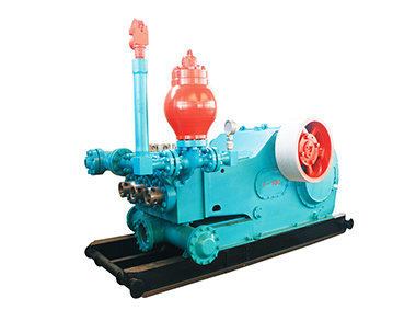
F2000 triplex piston mud pumps are firm and compact in structure and small in size, with good functional performances, which can adapt to drilling technological requirements such as oilfield high pump pressure and large displacement etc. The F series mud pumps can be maintained at lower stroke rate for their long stroke, which effectively improves the feeding water performance of mud pumps and prolongs the service life of the fluid end. The suction stabilizer, with advanced structure and reliable service, can achieve the best buffering effect. Power ends of the F series mud pumps adopt the reliable combination of forced lubrication and splash lubrication to increase the service life of power ends.


 8613371530291