
mud pump motor free sample

The 2,200-hp mud pump for offshore applications is a single-acting reciprocating triplex mud pump designed for high fluid flow rates, even at low operating speeds, and with a long stroke design. These features reduce the number of load reversals in critical components and increase the life of fluid end parts.
The pump’s critical components are strategically placed to make maintenance and inspection far easier and safer. The two-piece, quick-release piston rod lets you remove the piston without disturbing the liner, minimizing downtime when you’re replacing fluid parts.
Explore a wide variety of dc mud pump motor on Alibaba.com and enjoy exquisite deals. The machines help maintain drilling mud circulation throughout the project. There are many models and brands available, each with outstanding value. These dc mud pump motor are efficient, durable, and completely waterproof. They are designed to lift water and mud with efficiency without using much energy or taking a lot of space.
The primary advantage of these dc mud pump motor is that they can raise water from greater depths. With the fast-changing technology, purchase machines that come with the best technology for optimum results. They should be well adapted to the overall configuration of the installation to perform various operations. Hence, quality products are needed for more efficiency and enjoyment of the machines" full life expectancy.
Alibaba.com offers a wide selection of products with innovative features. The products are designed for a wide range of flow rates that differ by brand. They provide cost-effective options catering to different consumer needs. When choosing the right dc mud pump motor for the drilling project, consider factors such as size, shape, and machine cost. More powerful tools are needed when dealing with large projects such as agriculture or irrigation.
Alibaba.com provides a wide range of dc mud pump motor to suit different tastes and budgets. The site has a large assortment of products from major suppliers on the market. The products are made of durable materials to avoid corrosion and premature wear during operations. The range of products and brands on the site assures quality and good value for money.
Triplex mud pumps pump drilling mud during well operations. An example of a typical triplex mud pump 10 shown in FIG. 1A has a power assembly 12, a crosshead assembly 14, and a fluid assembly 16. Electric motors (not shown) connect to a pinion shaft 30 that drives the power assembly 12. The crosshead assembly 14 converts the rotational movement of the power assembly 12 into reciprocating movement to actuate internal pistons or plungers of the fluid assembly 16. Being triplex, the pump"s fluid assembly 16 has three internal pistons to pump the mud.
As shown in FIG. 1B, the pump"s power assembly 14 has a crankshaft 20 supported at its ends by double roller bearings 22. Positioned along its intermediate extent, the crankshaft 20 has three eccentric sheaves 24-1 . . . 24-3, and three connecting rods 40 mount onto these sheaves 24 with cylindrical roller bearings 26. These connecting rods 40 connect by extension rods (not shown) and the crosshead assembly (14) to the pistons of the pump"s fluid assembly 16.
In addition to the sheaves, the crankshaft 20 also has a bull gear 28 positioned between the second and third sheaves 24-2 and 24-3. The bull gear 28 interfaces with the pinion shaft (30) and drives the crankshaft 20"s rotation. As shown particularly in FIG. 1C, the pinion shaft 30 also mounts in the power assembly 14 with roller bearings 32 supporting its ends. When electric motors couple to the pinion shaft"s ends 34 and rotate the pinion shaft 30, a pinion gear 38 interfacing with the crankshaft"s bull gear 28 drives the crankshaft (20), thereby operating the pistons of the pump"s fluid assembly 16.
When used to pump mud, the triplex mud pump 10 produces flow that varies by approximately 23%. For example, the pump 10 produces a maximum flow level of about 106% during certain crankshaft angles and produces a minimum flow level of 83% during other crankshaft angles, resulting in a total flow variation of 23% as the pump"s pistons are moved in differing exhaust strokes during the crankshaft"s rotation. Because the total flow varies, the pump 10 tends to produce undesirable pressure changes or “noise” in the pumped mud. In turn, this noise interferes with downhole telemetry and other techniques used during measurement-while-drilling (MWD) and logging-while-drilling (LWD) operations.
In contrast to mud pumps, well-service pumps (WSP) are also used during well operations. A well service pump is used to pump fluid at higher pressures than those used to pump mud. Therefore, the well service pumps are typically used to pump high pressure fluid into a well during frac operations or the like. An example of a well-service pump 50 is shown in FIG. 2. Here, the well service pump 50 is a quintuplex well service pump, although triplex well service pumps are also used. The pump 50 has a power assembly 52, a crosshead assembly 54, and a fluid assembly 56. A gear reducer 53 on one side of the pump 50 connects a drive (not shown) to the power assembly 52 to drive the pump 50.
As shown in FIG. 3, the pump"s power assembly 52 has a crankshaft 60 with five crankpins 62 and an internal main bearing sheave 64. The crankpins 62 are offset from the crankshaft 60"s axis of rotation and convert the rotation of the crankshaft 60 in to a reciprocating motion for operating pistons (not shown) in the pump"s fluid assembly 56. Double roller bearings 66 support the crankshaft 60 at both ends of the power assembly 52, and an internal double roller bearing 68 supports the crankshaft 60 at its main bearing sheave 64. One end 61 of the crankshaft 60 extends outside the power assembly 52 for coupling to the gear reducer (53; FIG. 2) and other drive components.
As shown in FIG. 4A, connecting rods 70 connect from the crankpins 62 to pistons or plungers 80 via the crosshead assembly 54. FIG. 4B shows a typical connection of a connecting rod 70 to a crankpin 62 in the well service pump 50. As shown, a bearing cap 74 fits on one side of the crankpin 62 and couples to the profiled end of the connecting rod 70. To reduce friction, the connection uses a sleeve bearing 76 between the rod 70, bearing cap 74, and crankpin 62. From the crankpin 62, the connecting rod 70 connects to a crosshead 55 using a wrist pin 72 as shown in FIG. 4A. The wrist pin 72 allows the connecting rod 70 to pivot with respect to the crosshead 55, which in turn is connected to the plunger 80.
In use, an electric motor or an internal combustion engine (such as a diesel engine) drives the pump 50 by the gear reducer 53. As the crankshaft 60 turns, the crankpins 62 reciprocate the connecting rods 70. Moved by the rods 70, the crossheads 55 reciprocate inside fixed cylinders. In turn, the plunger 80 coupled to the crosshead 55 also reciprocates between suction and power strokes in the fluid assembly 56. Withdrawal of a plunger 80 during a suction stroke pulls fluid into the assembly 56 through the input valve 82 connected to an inlet hose or pipe (not shown). Subsequently pushed during the power stroke, the plunger 80 then forces the fluid under pressure out through the output valve 84 connected to an outlet hose or pipe (not shown).
In contrast to using a crankshaft for a quintuplex well-service pump that has crankpins 62 as discussed above, another type of quintuplex well-service pump uses eccentric sheaves on a direct drive crankshaft. FIG. 4C is an isolated view of such a crankshaft 90 having eccentric sheaves 92-1 . . . 92-5 for use in a quintuplex well-service pump. External main bearings (not shown) support the crankshaft 90 at its ends 96 in the well-service pumps housing (not shown). To drive the crankshaft 90, one end 91 extends beyond the pumps housing for coupling to drive components, such as a gear box. The crankshaft 90 has five eccentric sheaves 92-1 . . . 92-5 for coupling to connecting rods (not shown) with roller bearings. The crankshaft 90 also has two internal main bearing sheaves 94-1, 94-2 for internal main bearings used to support the crankshaft 90 in the pump"s housing.
In the past, quintuplex well-service pumps used for pumping frac fluid or the like have been substituted for mud pumps during drilling operations to pump mud. Unfortunately, the well-service pump has a shorter service life compared to the conventional triplex mud pumps, making use of the well-service pump as a mud pump less desirable in most situations. In addition, a quintuplex well-service pump produces a great deal of white noise that interferes with MWD and LWD operations, further making the pump"s use to pump mud less desirable in most situations. Furthermore, the well-service pump is configured for direct drive by a motor and gear box directly coupling on one end of the crankshaft. This direct coupling limits what drives can be used with the pump. Moreover, the direct drive to the crankshaft can produce various issues with noise, balance, wear, and other associated problems that make use of the well-service pump to pump mud less desirable.
One might expect to provide a quintuplex mud pump by extending the conventional arrangement of a triplex mud pump (e.g., as shown in FIG. 1B) to include components for two additional pistons or plungers. However, the actual design for a quintuplex mud pump is not as easy as extending the conventional arrangement, especially in light of the requirements for a mud pump"s operation such as service life, noise levels, crankshaft deflection, balance, and other considerations. As a result, acceptable implementation of a quintuplex mud pump has not been achieved in the art during the long history of mud pump design.
What is needed is an efficient mud pump that has a long service life and that produces low levels of white noise during operation so as not to interfere with MWD and LWD operations while pumping mud in a well.
A quintuplex mud pump is a continuous duty, reciprocating plunger/piston pump. The mud pump has a crankshaft supported in the pump by external main bearings and uses internal gearing and a pinion shaft to drive the crankshaft. Five eccentric sheaves and two internal main bearing sheaves are provided on the crankshaft. Each of the main bearing sheaves supports the intermediate extent of crankshaft using bearings. One main bearing sheave is disposed between the second and third eccentric sheaves, while the other main bearing sheave is disposed between the third and fourth eccentric sheaves.
One or more bull gears are also provided on the crankshaft, and the pump"s pinion shaft has one or more pinion gears that interface with the one or more bull gears. If one bull gear is used, the interface between the bull and pinion gears can use herringbone or double helical gearing of opposite hand to avoid axial thrust. If two bull gears are used, the interface between the bull and pinion gears can use helical gearing with each having opposite hand to avoid axial thrust. For example, one of two bull gears can be disposed between the first and second eccentric sheaves, while the second bull gear can be disposed between fourth and fifth eccentric sheaves. These bull gears can have opposite hand. The pump"s internal gearing allows the pump to be driven conventionally and packaged in any standard mud pump packaging arrangement. Electric motors (for example, twin motors made by GE) may be used to drive the pump, although the pump"s rated input horsepower may be a factor used to determine the type of motor.
Connecting rods connect to the eccentric sheaves and use roller bearings. During rotation of the crankshaft, these connecting rods transfer the crankshaft"s rotational movement to reciprocating motion of the pistons or plungers in the pump"s fluid assembly. As such, the quintuplex mud pump uses all roller bearings to support its crankshaft and to transfer crankshaft motion to the connecting rods. In this way, the quintuplex mud pump can reduce the white noise typically produced by conventional triplex mud pumps and well service pumps that can interfere with MWD and LWD operations.
Turning to the drawings, a quintuplex mud pump 100 shown in FIGS. 5 and 6A-6B has a power assembly 110, a crosshead assembly 150, and a fluid assembly 170. Twin drives (e.g., electric motors, etc.) couple to ends of the power assembly"s pinion shaft 130 to drive the pump"s power assembly 110. As shown in FIGS. 6A-6B, internal gearing within the power assembly 110 converts the rotation of the pinion shaft 130 to rotation of a crankshaft 120. The gearing uses pinion gears 138 on the pinion shaft 130 that couple to bull gears 128 on the crankshaft 120 and transfer rotation of the pinion shaft 130 to the crankshaft 120.
For support, the crankshaft 120 has external main bearings 122 supporting its ends and two internal main bearings 127 supporting its intermediate extent in the assembly 110. As best shown in FIG. 6A, rotation of the crankshaft 120 reciprocates five independent connecting rods 140. Each of the connecting rods 140 couples to a crosshead 160 of the crosshead assembly 150. In turn, each of the crossheads 160 converts the connecting rod 40"s movement into a reciprocating movement of an intermediate pony rod 166. As it reciprocates, the pony rod 166 drives a coupled piston or plunger (not shown) in the fluid assembly 170 that pumps mud from an intake manifold 192 to an output manifold 198. Being quintuplex, the mud pump 100 has five such pistons movable in the fluid assembly 170 for pumping the mud.
The cross-section in FIG. 10A shows a crosshead 160 for the quintuplex mud pump. The end of the connecting rod 140 couples by a wrist pin 142 and bearing 144 to a crosshead body 162 that is movable in a crosshead guide 164. A pony rod 166 coupled to the crosshead body 162 extends through a stuffing box gasket 168 on a diaphragm plate 169. An end of this pony rod 166 in turn couples to additional components of the fluid assembly (170) as discussed below.
The cross-section in FIG. 10B shows portion of the fluid assembly 170 for the quintuplex mud pump. An intermediate rod 172 has a clamp 174 that couples to the pony rod (166; FIG. 10A) from the crosshead assembly 160 of FIG. 10A. The opposite end of the rod 172 couples by another clamp to a piston rod 180 having a piston head 182 on its end. Although a piston arrangement is shown, the fluid assembly 170 can use a plunger or any other equivalent arrangement so that the terms piston and plunger can be used interchangeably herein. Moved by the pony rod (166), the piston head 182 moves in a liner 184 communicating with a fluid passage 190. As the piston 182 moves, it pulls mud from a suction manifold 192 through a suction valve 194 into the passage 190 and pushes the mud in the passage 190 to a discharge manifold 198 through a discharge valve 196.
As noted previously, a triplex mud pump produces a total flow variation of about 23%. Because the present mud pump 100 is quintuplex, the pump 100 offers a lower variation in total flow, making the pump 100 better suited for pumping mud and producing less noise that can interfere with MWD and LWD operations. In particular, the quintuplex mud pump 100 can produce a total flow variation as low as about 7%. For example, the quintuplex mud pump 100 can produce a maximum flow level of about 102% during certain crankshaft angles and can produce a minimum flow level of 95% during other crankshaft angles as the pump"s five pistons move in their differing strokes during the crankshaft"s rotation. Being smoother and closer to ideal, the lower total flow variation of 7% produces less pressure changes or “noise” in the pumped mud that can interfere with MWD and LWD operations.
Although a quintuplex mud pump is described above, it will be appreciated that the teachings of the present disclosure can be applied to multiplex mud pumps having at least more than three eccentric sheaves, connecting rods, and fluid assembly pistons. Preferably, the arrangement involves an odd number of these components so such mud pumps may be septuplex, nonuplex, etc. For example, a septuplex mud pump according to the present disclosure may have seven eccentric sheaves, connecting rods, and fluid assembly pistons with at least two bull gears and at least two bearing sheaves on the crankshaft. The bull gears can be arranged between first and second eccentric sheaves and sixth and seventh eccentric sheaves on the crankshaft. The internal main bearings supporting the crankshaft can be positioned between third and fourth eccentric sheaves and the fourth and fifth eccentric sheaves on the crankshaft.
There is no shortage of questions to ask yourself before purchasing, leasing or renting a mud motor for your next job. There are a lot of options available for you to choose from. Knowing your needs, as well as how to care for your tooling so you can maximize its life expectancy are invaluable to the process.
“Without a mud motor, there would be many HDD jobs that would be near impossible to complete, at least not in a productive, profitable manner,” says Peter Melsheimer, marketing director atMelfred Borzall, a pioneering company in the design and development of horizontal drilling tools. “There are a few different ways to get though solid rock using an HDD drill, but when it comes to a job that involves longer bores and the potential for a variety of formations, the mud motor is really the way to go.”
After years of use in the oilfields, the evolution of the mud motor and its impact on the HDD industry has been significant, allowing drillers to get through the toughest of formations and opening the door for more challenging projects. “Without this ability, the [HDD] industry would be extremely limited,” says Greg Wilson, president of Sharewell Inc., a Texas-based, leading supplier of downhole drilling tools, guidance systems and services for the HDD industry.
When it comes to manufacturing and supplying mud motors, the HDD industry is not in short supply. We spoke with a few mud motors manufacturers on selecting this tool, its care and maintenance, as well as some common missteps that contractors can make when operating one on the job.
Having a handle on your project needs will make selecting the proper mud motor much easier. A few things you should know include: pump volume, pilot hole diameter and bend ability. First up: pump volume, which powers the downhole motor.
“When selecting a downhole mud motor, the contractor must consider their pumps’ volume capability,” Wilson says. “While motors will operate with low volumes, it is advisable to pick a motor that has a maximum volume requirement capable of being achieved by their pump. When the flow is at the low end of the motor’s requirement, the torque, ability for the drill bit to cut the rock, is greatly reduced, causing slow or no penetration through the rock.”
A key step in the purchase process is recognizing the formation you will be drilling in, especially when you are getting a combination of tooling such as drill bits and a mud motor. “Bits are classified by IADC codes that guide a purchaser through the selection of an appropriate bit for the formation to be drilled. Different bits will be rotated at different RPMs for different formations, so knowing as much about the formation as possible is important for not only bit selection but also for the selection of an appropriate mud motor,” says Sean Teer, U.S. operations supervisor at Prime Horizontal, a provider of innovative guidance products and solutions for the steering of difficult HDD projects. “That said, different mud motors will achieve higher RPMs with different mud flow rates, therefore, a pump and mud motor must be matched appropriately for the best performance on the expected formation.”
Wilson notes that contractors need to keep in mind the size of the pilot hole they will be drilling because each motor has a specific bit range that it is capable of drilling with. “This is an important consideration because a bit that is too small could cause the drill pipe to get stuck. A bit that is too large can cause premature wear on the bearings of the motor and make it difficult to steer.”
Teer agrees, adding, “Although connection size can be adapted so that a larger bit can fit a smaller motor, typically bits of a certain connection size will be paired with mud motors of compatible or same connection size. The torque specifications for the mud motor at the desired flow rate must be taken into account when deciding on the bit and mud motor combination.”
Contractors also need to keep in mind that the mud motor has to bend because that affects steerability. “This bend is measured in degrees, and on some mud motors, it is adjustable within a range,” says Teer. “Another point about steerability that should be considered is the length of the motor. In most cases, a mud motor increases the ‘bit lead’ or distance between the guidance sensor and the bit, causing a larger distance of unknown change along the drill path.”
OK, you have the right mud motor! Having the proper equipment means nothing if you are not using it correctly, thereby inhibiting your project and possibly causing early retirement for your tooling. There are things that a driller does that will not allow the mud motor to work to its maximum capability — such as not using clean mud.
If a mud motor is rotated without mud flowing through, it can draw in fluids from downhole, says Teer. These fluids will not be the clean mud that is driving the mud motor and may contain sand, gravel, clay or other materials found downhole, all of which are problematic for the inside of the mud motor. “A mud motor operates by passing the flow of mud through lobes created between the rotating ‘rotor’ and the elastomer ‘stator,’” he explains. “If these lobes are plugged, mud will not flow and rotation will not be created. This will create a seized mud motor. For this reason, only clean mud should be pumped through mud motors and some LCMs (lost circulation material) should not be pumped when using a mud motor.”
Drillers also need to be mindful of just how much drilling fluid they are going through and the equipment required to contain and reclaim the fluid. “It’s a common mistake. A driller may be accustomed to drilling at 10 ft in just a couple minutes using about 20 gpm,” says Melsheimer. “With a small motor in rock, he may be drilling 10 ft every 20 minutes and going through 50 gpm. On a 300-ft shot that could be the difference of 1,200 gallons of drill fluid vs. 30,000 gals. This is an example on a small project, but results in a huge difference in drill fluid usage.
Melsheimer also notes this common misstep when using a mud motor: Not realizing that you need a special “high-flow” transmitter housing. “The typical ‘side-load’ housing used with conventional HDD has just one to two fluid ports. When trying to pump a maximum amount of drill fluid through the housing to ‘feed’ the mud motor, it can result in a pressure restriction,” he says. “This restriction will steal the power of the mud motor making it inoperable or at a minimum much, much less efficient. A ‘high-flow’ housing has multiple fluid ports drilled straight through the transmitter housing allowing for maximum flow with minimal restrictions. These types of housings can cost two to four times what a standard housing costs.”
So you have done your homework and you have a brand-spanking new mud motor in your drilling toolbox. What now? You want to get the maximum amount of usage out of the tool. Proper care and handling go a long way in achieving that goal.
Generally speaking, the life expectancy of a mud motor as a whole unit is fairly long. Run properly, a driller should be able to get 100 to 200 hours of operation out of their mud motor before it would need to have its routine maintenance, says Melsheimer.
Like any tool that involves rotating shafts, bearings, seals, rubber and parts with tight tolerances, how the motor is run and how it is maintained can have huge implications on its life expectancy, he says.
Mud motors are designed with wear-and-tear in mind and manufacturers recommend that it be broken down and reassembled with replacement parts, when necessary, after each job. Some of the wear parts include the bearings (which take the brunt of all the forces exerted on the mud motor), the external parts and the internal elastomer, a part that is constantly subjected to the flow of mud that will, in some cases, have a sand content that will expedite the elastomer’s normal wear and tear, Teer says.
“The fact that any overly worn parts are replaced each time the motor is returned and serviced makes the life of the motor virtually never ending,” Wilson says.
To assist in keeping your mud motor in top working condition, here are few tips, including keeping an eye on the tool’s differential pressure. “The differential pressure is the difference in the mud flow pressure when the bit is free spinning in the open hole and when the bit is actually against the rock face,” Wilson says.
“Each motor will have a maximum allowable differential pressure. Once the maximum pressure is exceeded, the bit will stall, causing excessive wear to the internal components of the motor.”
Critical to the mud motor’s upkeep is the use of clean mud. Simply stated, the more sand and solids in the drilling fluid, the faster the internal parts of the motor will wear down. “The sand content of the drilling fluids needs to be constantly monitored and kept low,” Teer says. “This will extend the life of the mud motor’s elastomer and the mud motor will behave as intended.”
There are several questions that need to be addressed before we can move forward on this topic: How hard is the rock? Do we know what type of rock it is? What rig are you considering to use? How much mud pump volume (gpm) does your pump produce? How long is the bore? These are the opening questions that if answers are known, typically produce additional questions. If the rock has been tested to be 15,000 psi, I can move to the next question, but often all that is available is blow counts from a core sample run in the area. If that’s the case, I need to make some educated assumptions and move on. Looking at the type of rock gives me an indication of the potential wear on the motor — for example, shale is far more forgiving than sandstone. My customer now tells me he plans on using an 80,000-lb drill with a 250-gpm mud pump and the bore is 800 ft long. I now have enough information to make a recommendation for a mud motor for this project. Rock hardness is 15,000 psi in strength. The formation has been determined to be shale and limestone. We have an 80,000-lb drill with 250-gpm pump. Based on this information I can recommend a 4-3/4-in. mud motor.
This mud motor, as all manufactured motors do, has a specific flow range it operates in. For this size, it is 150 to 250 gpm. We try to optimize the flow rate to the motor to utilize its optimum torque output and rotation at the bit box. This should produce the best penetration rates and steerability in the rock — two things we always want to maximize (within the limits of hole cleaning ability). Other considerations are drill pipe outer diameter (OD). We hope to have the pipe similar in OD as the motor, which should mean similar mechanical limitations.
Now we can look at a bit size. As with the recommended flow range, there is a recommended bit size (OD) range. For a 4-3/4-in. mud motor, it is 6 to 7-7/8 in. Most of the time we like to see a bit in the 6-½- to 6-¾-in. size used. This will give the motor enough annulus area to properly reside in and also allow it to have the ability to properly steer. Oversized bits, for example an 8-½-in. bit on a 4-¾-in. mud motor, will not allow the motor to steer. The motor can’t contact the inner diameter of the bore hole, which eliminates the fulcrum effect of the bend in the mud motor.
If run within the operations manual specifications, the mud motor should perform within the published parameters up to 100 to 125 hours of drilling. At that time, it is recommended to be returned to the supplier for service and inspection. Typically at that time, we see the bearings out of tolerance and needing replaced. Obviously this is what we like to see but in our industry we face situations daily that can affect operations on the jobsite. We see many motors returned with 150-plus hours on them and usually these additional hours show on the repair bill. The internal workings of the transmission section are usually affected by the added hours, which will increase repair cost.
The most expensive replacement on the mud motor is the power section. This is comprised of the stator and rotor. The rotor is typically chrome-plated steel and has one less lobe than the stator, which its inner diameter is made of a highly engineered rubber compound. The drilling mud is pumped through the rotor-stator assembly, creating torque and rotation at the drill bit. This means the drilling mud needs to be clean of solids and sand. If it is not clean, it will prematurely wear the stator and the rotor, increasing the fit between the two, which dramatically reduces the pressure and power this section is designed to produce.
We once had a customer who bought a 6-¾-in. mud motor and after a month, I called to check to see if it needed service. I was told it was doing great and was in the hole on its third bore. I reminded the customer that service of the motor was critical to the overall life of the tool, but apparently it fell on deaf hears. Six months later, the customer called and said he was sending it in for service. I asked if he knew how many hours they had on it — I was told in excess of 750! Needless to say, the tool was retired and the rotor was made into a front bumper for one of their work trucks.
Service the motor every 100 to 125 hours of use and the overall life of the motor will be extended. Minimize motor stalls — this is when the motor stops turning internally while the mud pump is still pumping mud through it. After a motor is used on a job and doesn’t require service, we recommend that fresh water be pumped through it to flush out the drilling mud which will dry out and can cause damage when the motor is reused.
As long as a rig has the required gpm and pressure rating — I can answer a qualified yes. Let’s assume a contractor has a rig with a pump rated at 150 gpm by its manufacturer. This rating is based on pumping water with a new pump. So realistically, we have a pump that will probably pump mud at 100 to 120 gpm. This is enough flow to power a 3-½-in. mud motor in its mid flow range requirements. At that flow rate, we can check the motor’s performance curve and find we have around 550 ft-lbs of torque at 150 rpm. This will work well enough in rock up to 15,000 psi. But if the project is in rock that is 25,000 psi, it will dramatically reduce the penetration rate, lowering the ROP to a point that it becomes economically not feasible. In this case, the contractor would need a larger rig with a bigger mud pump to power a larger mud motor to overcome the compressive strength of the rock.
Another issue to consider when using a mud motor is the contractor’s ability to recycle and clean his drilling mud. If you are pumping 100 gpm, you will drain a 1,000 gal mud mixing system in 10 minutes, an obvious reason to recycle drilling mud.
Probably the most common mistake is what is done when a motor stalls out. A stall-out occurs when the bit stops turning while pumping. We have three mud pump pressure readings we monitor while using a mud motor. The first is the off bottom pump pressure reading; the second is the on bottom pump pressure reading; the third is the stall pressure reading.
Let’s say our contractor has an off bottom pressure reading of 500 psi and an on bottom reading of 750 psi. While drilling, he applies too much weight on the bit, causing it to stop turning. The pressure now reads 825 psi. At this point most drillers pull the motor off bottom and resume drilling. This method will send reactive torque up the drill string and could cause the motor or drill pipe to unscrew. The correct action to take when a motor stalls is to turn the pump off, and then pull the motor off bottom. Then, restart the pump and advance to bottom.
Another area of concern is the fact that you are doing your locating behind the mud motor. You have your drill bit, mud motor and crossover sub, then your steering system. It doesn’t matter if you are using a wireline steering tool or a walkover system — if the rig is using a 4-¾-in. mud motor, your steering system is 20 ft behind the drill bit. This usually causes the driller to overreact and drill an S-curved pilot hole. He sees he is heading right of centerline so he steers left, then he sees he is heading left so he steers right so on and so on. This situation will correct itself as the operator becomes used to drilling with a mud motor.

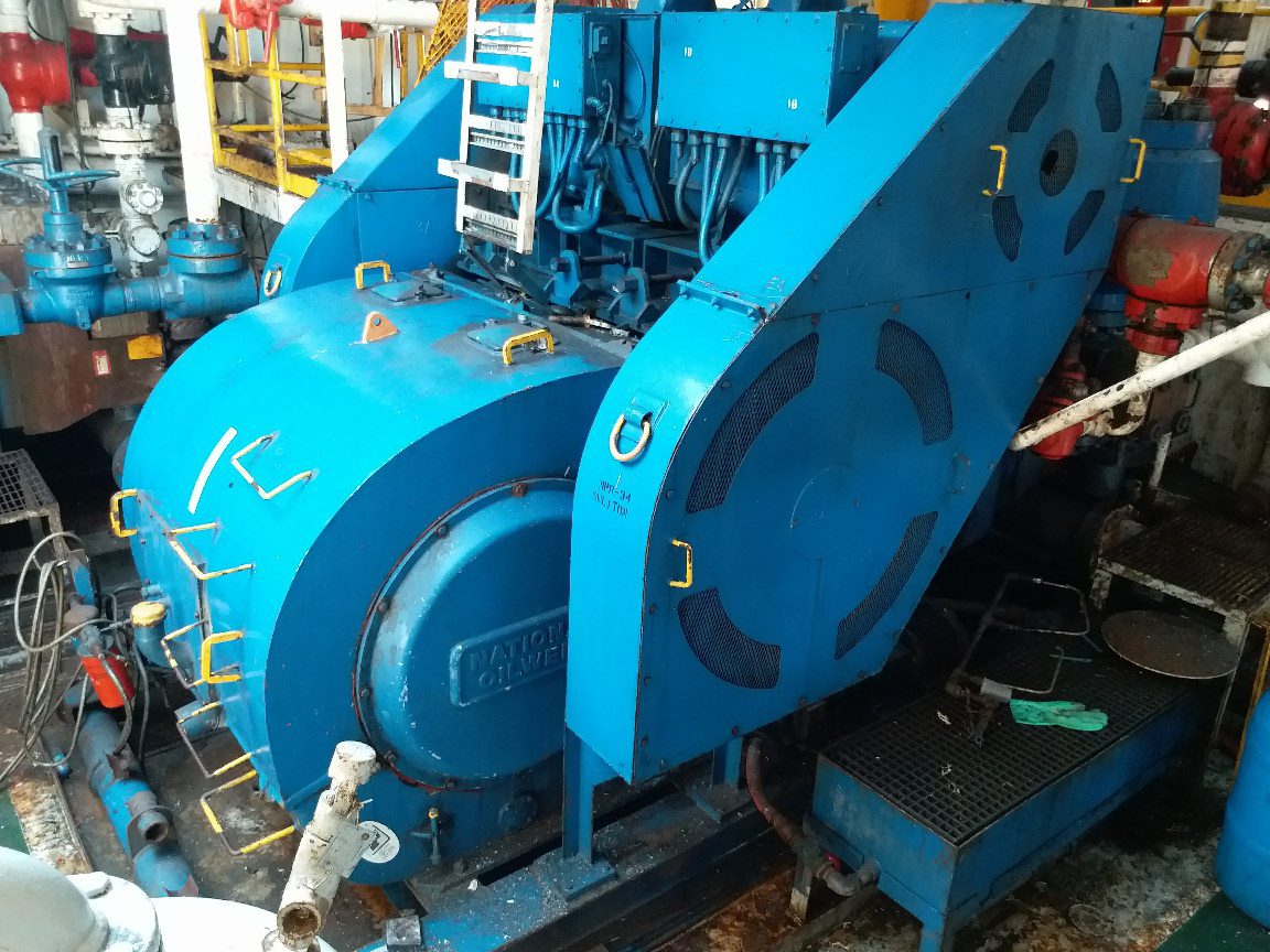
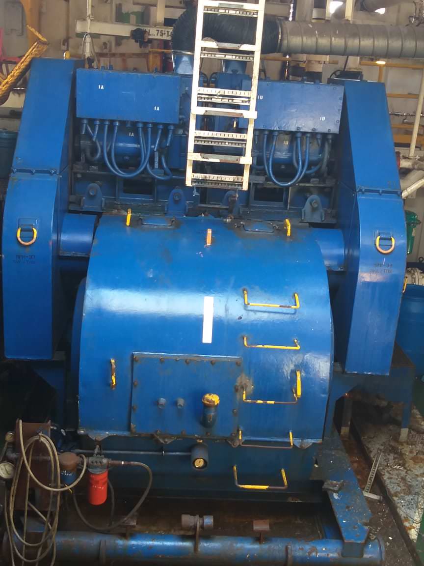
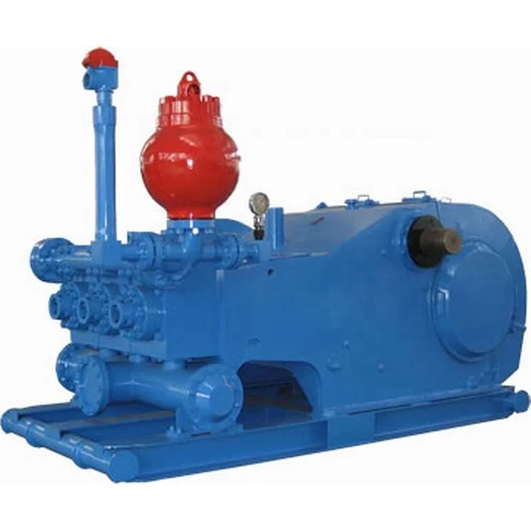
The NOV FC-1600 Triplex Mud Pump is made of rugged Fabriform construction and designed for optimum performance under extreme drilling conditions. It is compact and occupies less space, yet delivers unequaled performance. The pumps are backed by several decades of design and manufacturing experience, and are considered leaders in the field.
NOV FC-1600 Triplex Mud Pump is conservatively rated at relatively low rpm. This reduces the number of load reversals in heavily stressed components and increases the life of the fluid end parts through conservative speeds and valve operation.
The NOV FC-1600 Triplex Mud Pump design provides an inherently balanced assembly. No additional counterbalancing is required for smooth operation. No inertia forces are transmitted to the pumps’ mountings.
A Triplex Mud Pump sometimes referred to as a drilling mud pump or mud drilling pump. NOV FC-1600 Triplex Mud Pump is a reciprocating piston/plunger pump designed to circulate drilling fluid under high pressure (up to 7,500 psi) down the drill string and back up the annulus. A mud pump is an important part of the equipment used for oil well drilling.

The shaft power - the power required transferred from the motor to the shaft of the pump - depends on the efficiency of the pump and can be calculated as Ps(kW) = Ph(kW)/ η (3)

A mud motor (or drilling motor) is a progressive cavity positive displacement pump (PCPD) placed in the drill string to provide additional power to the bit while drilling. The PCPD pump uses drilling fluid (commonly referred to as drilling mud, or just mud) to create eccentric motion in the power section of the motor which is transferred as concentric power to the drill bit. The mud motor uses different rotor and stator configurations to provide optimum performance for the desired drilling operation, typically increasing the number of lobes and length of power assembly for greater horsepower. In certain applications, compressed air, or other gas, can be used for mud motor input power. Normal rotation of the bit while using a mud motor can be from 60 rpm to over 100 rpm.
Normal mud motor construction consists of a top sub, which connects the mud motor to the drill string; the power section, which consists of the rotor and stator; the transmission section, where the eccentric power from the rotor is transmitted as concentric power to the bit using a constant-velocity joint; the bearing assembly which protects the tool from off bottom and on bottom pressures; and the bottom sub which connects the mud motor to the bit.
When the bit is bottomed and the motor is effectively working, there is a notable increase in the pressure in the fluid system. This is caused by a restriction within the motor and is termed the "differential pressure". If this differential pressure is too high then the motor can stall which means the bit has stopped turning and this can cause severe damage to the internal surface of the stator.
A mud motor is described in terms of its number of stages, lobe ratio and external diameter. Stages are the number of full twists that the stator makes from one end to the other and the lobe ratio is the number of lobes on the stator, to the number of lobes on the rotor (the stator always has one more lobe than the rotor). A higher number of stages indicates a more powerful motor. A higher number of lobes indicates a higher torque output (for a given differential pressure), a lower number of lobes indicates a reduction in the torque produced but a faster bit rotation speed.
The operating parameters include flow rate, bit rpm and torque. The relationship between the rotor and the stator geometry determines the rotational speed and torque. The rotational speed is proportional to the flow rate and torque is proportional to the pressure drop in the fluid as it flows through the motor. The more lobes the higher the torque and the slower the rpm.
The use of mud motors is greatly dependent on financial efficiency. In straight vertical holes, the mud motor may be used solely for increased rate of penetration (ROP), or to minimize erosion and wear on the drill string, since the drill string does not need to be turned as fast.
The majority of mud motor use is in the drilling of directional holes. Although other methods may be used to steer the bit to the desired target zone, they are more time-consuming, which adds to the cost of the well. Mud motors can be configured to have a bend in them using different settings on the motor itself. Typical mud motors can be modified from 0 degrees to 4 degrees with approximately six increments in deviation per degree of bend. The amount of bend is determined by rate of climb needed to reach the target zone. By using a measurement while drilling (MWD) tool, a directional driller can steer the bit to the desired target zone.
Steerable motors are used to drill the kick-off point. When drilling the kick-off point be sure to avoid drilling a soft formation immediately below a hard one. In hard abrasive formations the high-side forces at kick off can cause severe bit shank wear. Ideally the kick-off point should be selected in a non-abrasive homogenous formation.
The PCPD stator, which is a major component of the pump, is usually lined with an elastomer. Most of PCPD pump failures are due to this elastomer part. However, the operating conditions
The mud motor may be sensitive to fouling agents. This means that certain types of drilling fluids or additives may ruin the motor or lower its performance. One particular example, as mentioned above, would be the use of oil based mud with the mud motor. Over time the oil degrades the elastomers and the seals in the motor.
Poor rotor/stator fit – improper tolerances due to degradation with time. Also if the fit is wrong then the differential pressure may be either too high or too low. Too high and it may damage the motor; too low and the motor will be weak and stall which may lead to stator chunking.
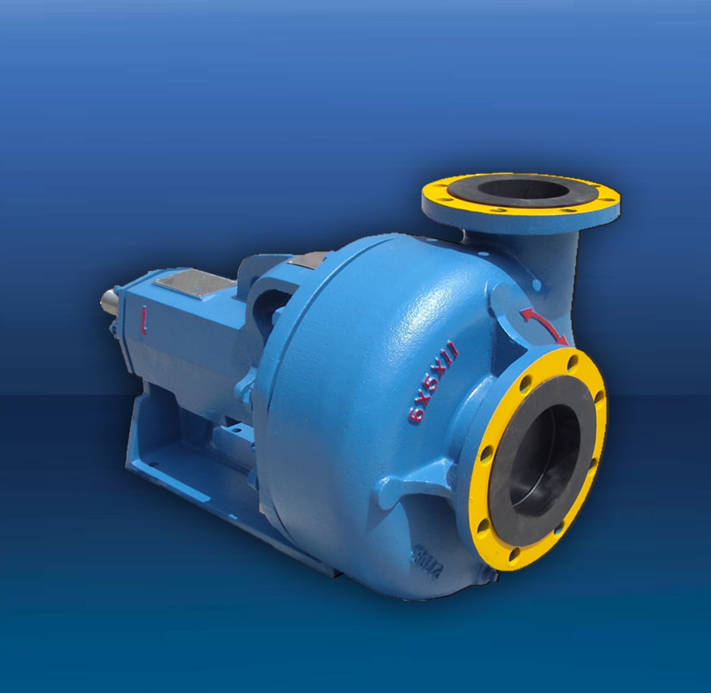
The motor used to power a centrifugal pump needs to be able to produce enough torque to start the pump and bring it to an optimal operating speed. If a motor lacks enough torque to operate a pump, the pump may not start or may only operate at a reduced speed. The centrifugal pump suppliers at PumpWorks will guide you through the pump motor selection process.
A pump’s torque-speed curve is used to determine the appropriate motor to match with it. A pump’s torque-speed curve is produced by plotting the percentage of full load torque (FLT) vertically against the percentage of full load speed (FLS) plotted horizontally. An example is shown below.
The torque-speed curve is similar for all centrifugal pumps due to simple math: the pump torque varies as the square of its speed. However, when the pump is at rest—0% full load speed—the full load torque is never also 0%. Starting a rotating pump requires the motor to overcome the pump inertia and static friction.
To overcome pump inertia and static friction, approximately 20% of full load torque is required. As the pump’s speed increases, the required torque gradually declines. For example, at about 15% full load speed the required torque typically is around 5% or 10% full load torque. As shown below, the pump torque-speed curve follows the square law:
Like pumps, motors produce a torque-speed curve of their own. By overlaying the torque-speed curve of a pump and a motor, one can verify that the motor is producing enough accelerating torque to drive the pump to full speed, as shown below.
In this overlay the shaded area reflects the accelerating torque available from the motor to drive the pump. Where the two curves intersect is the point at which the motor’s torque is insufficient to drive the pump any faster. In other words, this is the point of maximum pump speed while powered by this motor.
A motor’s horsepower (HP) is used as a baseline measure of its capabilities in the field. HP is a combination of torque and speed (RPM), with 1 HP equal to 550 foot pounds per second, or 33,000 foot pounds per minute. A motor’s torque can be calculated using its horsepower using this formula, which is derived from an expression of HP as a function of torque:
Torque at zero flow is especially important for pumps with axial flow (or propeller) designs. The torque-speed curve of such pumps is such that the highest HP, and therefore the highest torque, is required at zero flow. An axial-flow pump must be paired with a motor with adequate HP to get the pump moving.
Another important factor in motor selection is the pump’s inertia value at the motor shaft. Inertia is a measure of an object’s resistance to movement change. The higher the pump inertia, the longer the motor will take to start the pump and bring it to full load speed.
This is significant because motors draw current to bring pumps up to speed. The longer a motor takes to overcome a pump’s inertia, the more heat it will generate. A motor must be sized to handle the pump’s inertia to avoid damaging the motor’s windings.
If a motor directly drives the pump, the values of the pump and pump-motor coupling inertias are the same regardless of pump speed. If the pump is driven by a gearbox and motor, however, the gearbox can have a major impact on inertia values. In this application inertia can be expressed as:
A gearbox’s effect on inertia can be understood by analogy to a bicycle. When a bicycle is ridden at high speeds, the rider may change to a higher gear ratio (one greater than 1.0) to go faster. Such a ratio also requires the rider to put in more effort. Likewise, if a gearbox shifts to a higher gear ratio, the motor will have a higher load. The same logic applies if the gearbox is reducing the motor speed to drive the pump slower. When the gearbox ratio is less than 1.0, it will reduce the load requirements on the motor.
Selecting the right pump and motor for a specific application can be a complex job. The team at PumpWorks is dedicated to finding pump solutions that meet the exact needs of each customer.

This short paper will cover the basic building blocks of pump control. It is not intended to be the end-all for water and wastewater applications, but rather an introduction.
Water and waste water treatment requires moving water through the different stages of treatment. To do that, pump stations are used. Each part or station of the water treatment process can require a different type of pump. While the pumps are different, they all share the common architecture of an electric motor and a method of controlling those motors.
According to the US EPA, pump station capacities range from 76 lpm (20 gpm) to more than 378,500 lpm (100,000 gpm). Prefabricated pump stations generally have a capacity of up to 38,000 lpm (10,000 gpm). Usually, pump stations include at least two constant-speed pumps ranging in size from 38 to 75,660 lpm (10 to 20,000 gpm) each and have a basic wet-well level control system to sequence the pumps during normal operation. Source: EPA 832-F-00-069, September 2000
The process of moving water is extremely energy-intensive. In the US, electric motor-driven devices, including pumps, use almost 65%-70% of all electricity produced in the country. Water and wastewater systems are known to utilize almost 50% of the energy in any municipality, of which 90% of the energy is used by pumps.
Liquid level switches and sensors trigger when a desirable water level is attained. Trapped air column, or bubbler system that senses pressure and level, are commonly used for pump station controls. Other control alternatives are electrodes placed at cut-off levels and float switches. These sensors and switches signal the pump motor control systems to keep the water treatment process flowing and achieving optimum process efficiencies.
Municipal water systems use pumps to draw raw water from resources, such as lakes or rivers, for treatment to meet regulatory standards for potable water for human consumption or use in cooling towers, boilers, and other industrial applications.
Water and wastewater management has become a priority in industries such as chemical manufacturing, energy production, and food and pharmaceutical processing. The quality of water treatment entirely depends on the type of process employed. These treatment plants employ primary, secondary, and tertiary processes that vary depending on the level of contaminants in the water. The following are some popular pumps largely used in water and wastewater industry for water treatment.Positive Displacement Pumps
Proper pump, motor, and controls selection optimizes the performance of water treatment systems and can provide energy savings of 20% – 50%. Selecting a pump with the correct characteristics is achieved by studying pump performance curves. Below is an example of an ESP (Electric Submersible Pump) pump performance curve.
Types of Motor Controls used with Water and Wastewater PumpsContactor: Contactors are components designed to switch on and off heavy loads in pump motors. These components feature main contacts (poles), auxiliary contacts, and an operating coil. They energize the contactor to switch on and off the main contacts. Auxiliary contacts are designed for controlling and signaling various circuit applications, whereas main contacts are the current carrying parts of these contactors.
Typically these contactors feature 3-pole electrically operated switches, which take less space when installed inside electrical enclosures. The motors used in water treatment and wastewater treatment pumps are known to draw more energy at any voltage. The possibility of electric shock increases at high voltage and may cause heavy damage. However, AC and DC contactors are safe to use while starting the motor, as there is no current flow between the circuit powering a contactor and the circuit being switched.
The contactors are mounted so they do not touch the circuit that is being switched. Because these contactors use less power than the main switching circuit, they help reduce power consumption. Advanced motor contactors feature compact designs, which further help reduce the footprint of the device and its power consumption.Overload Relay: When a motor draws excess current, it is referred to as an overload. This may cause overheating of the motor and damage the windings of the motor. Because of this, it is important to protect the motor, motor branch circuit, and motor branch circuit components from overload conditions. Overload or overheating is one of the major reasons for pump failure. Overload Relays protect the pump’s motor from these conditions.
Bimetallic overload relays are one of the most common types of overload protection devices, and they feature adjustable trip points. Bimetallic overloads are engineered for automatic reclosing and compensate to prevent ambient temperature changes. In addition, these overload relays protect motors in extreme temperature environments.
Advanced bimetallic overload relays feature manual or automatic reset and test modes and a stop button that enables better device management. Many of these relays possess single phase sensitivity, which helps protect motors against phase loss conditions. These relays are provided in three trip class ratings:Class 10 is a quick trip rating, suitable for submersible pumps used in water and wastewater industries. This rating indicates that the bimetallic overload relay will trip automatically within 10 seconds of the overload condition.
These features help minimize energy consumption and increase motor efficiency.Motor Protection Circuit Breaker: Designed for protecting motors from short circuits, phase-loss, and overloads, motor protection circuit breakers (MPCB’s) are alternatives to thermal overload relays, and are equipped with several advanced features.
Commonly used in many water pumping systems, these circuit protection components are used as manual motor controllers or paired with contactors in several multi-motor applications. Motor protection circuit breakers are mainly distinguished as open or enclosed. The difference between these types is where the circuit breaker is secured, either inside an enclosure or open in the panel. Most advanced motor protection circuit breakers offer space savings, as they are designed without individual motor branch circuit fuses, overload relays, or circuit breakers.Direct-On-Line (DOL) Motor Starter: As the name suggests, these devices are used to start electric motors of pumps and other electronic devices such as compressors, conveyor belts, and fans. A motor starter features various electronic and electro-mechanical devices such as a contactor paired with a motor protection circuit breaker or an overload relay. DOL starters are used to start small water pumps because they provide several advantages such as 100% torque during starting, simplified control circuitry, easy installation and maintenance, and minimal wiring. Enclosed DOL Motor Starters are also an option, where the entire starter assembly is placed inside an enclosure.
Programmable Logic Controller (PLC): The programmable logic controller or PLC is really an industrialized computer that operates without a keyboard or monitor. Originally, the PLC was a replacement for large panels of relays that switched on and off, controlling a machine operation. The programming language of the PLC mimicked the Relay Logic, making the transition from relays to PLC’s an easy to understand process. Today’s PLC’s offer much more complex operational capabilities and communications via Ethernet or proprietary networks. The ability to control multiple pumps in a coordinated fashion make PLC’s a common component of water management systems.
Variable Frequency Drive (VFD): They’re used for running an AC motor at variable speeds or to ramp up speed for smoother start up. VFD’s control the frequency of the motor to adjust the pump motor RPM’s. VFD’s are widely used to regulate water flow at a water treatment plant, allowing more control over the flow of the pump.
Soft Starter: Between the simplicity of a DOL motor starter and the complexity of a VFD sits the Soft Starter. Electric motors often require large amounts of electricity during their acceleration. A soft starter can be used to limit the surge of current torque of the electric motors, resulting in a smoother startup. Soft starters can protect an electric motor from possible damage and at the same time extend the lifespan of your electric motor by reducing the heat caused by frequent starting and stopping. Soft Starters limit the large inrush current demands on the electrical supply system. Soft Starters are used with pumps in a process which requires to bring them up slowly to reduce pressure surges in the water system.
These devices are often confused with relays, however, the main difference is contactors can easily switch higher currents and voltages, whereas the relay is used for lower current applications. Keep the following in mind when selecting contactors for your motors:Decide what amount of current, FLA – Full Load Amperage will be required to power your pump motor.
Select the coil voltage for AC or DC operation based on your motor horsepower, input voltage, and single or 3-phase. Coils are mainly offered in control voltages such as 24VAC, 230VAC, 400VAC, 24VDC, and so on.
Selecting a contactor with an IEC Utilization Category of AC-3 is typical for pump applications requiring starting and switching off motors during run time.
When used in water or wastewater industries, overload relays are governed by strict requirements. With so many designs available, choosing the right overload relay may become difficult. These factors will simplify the selection process:Choose the overload relay that provides the most thermal overload protection. Overload relays help protect the motor from dangerous overheating, which causes motor failure. This protection takes electricity consumption of the motor into consideration and applies it to an overload model to simulate the thermal energy inside the motor. Most overload relays are designed on either of the two overload models: Two-Body and I2T models. Most bimetallic relays use the I2T overload model, whereas many medium or large voltage electric motors use the Two-Body model.
Phase loss protection is another important factor to consider, as phase loss is one of the major causes of motor failure. Phase loss occurs when the value of one phase equals to zero amps due to a blown phase. When the motor remains in this phase for a long time, it may be damaged permanently. Overload relays are designed to detect the phase loss condition, therefore it is important to understand the type of phase loss protection offered by overload relays.
Most pump systems in the market today include basic motor protection built into the motor or control box. This protection however is designed to safeguard against only current problems, therefore additional motor protection should be considered. There are many options available to choose from, each present slightly different performance characteristics under overload conditions. Factors to consider are:High fault short circuit current rating because it assures safety and reliability in extremely high fault applications.
Overload relays, contactors, and motor protection circuit breakers are largely used in the following applications.Influent and Effluent Pumps: The influent pumps are usually placed at the start of the wastewater treatment plant. The wastewater first enters into the influent pump, which pumps it to other parts of the treatment plant. Effluent pumps are used for treating water that may contain solids up to 3/4”.
Booster Pumps: These pumps are used for boosting the water pressure for use in light industrial and commercial applications. The booster pumps are mainly used for potable water applications.
Digested Sludge Pumps: Contaminated sludge is treated in wastewater treatment plants before being released into water bodies. The sludge contains solids which may block the pipeline, so special pumps are used for the purpose. Sometimes, sludge choppers are integrated into the pumps, or submersible centrifugal pumps are used for pumping fluids having high sludge content.
Submersible Pumps: As their name suggests, these pumps are completely submerged in the liquid. These pumps are used to drain the slurry or sewage and are mostly placed under the sewage or wastewater treatment plants. Their operation is controlled using advanced motors.
All motor controls referenced in this document are designed in accordance with standards published by NEMA (National Electrical Manufacturers Association) or IEC (International Electrotechnical Commission).
The NEMA starter, at its stated rating, can be used for a wide range of applications, ranging from simple on and off applications to plugging and jogging applications, which are more demanding. It is necessary to know the voltage and horsepower of the motor when selecting the proper NEMA motor starter. In the case where there is a considerable amount of plugging and jogging involved, then derating a NEMA-rated device will be required.
The International Electrotechnical Commission (IEC) has specified the operational and performance characteristics for IEC devices in the publication IEC 60947. Standard sizes are not specified by the IEC. The typical duty cycle of IEC devices are defined by utilization categories. As far as general motor starting applications are concerned, AC3 and AC4 are the most common utilization categories.
Below are three examples of pump control, using basic industrial motor controls. These are simple representations, and not intended to provide complete solutions.
We hope that this short paper has given you a good, basic understanding of pump control for water/wastewater. Look for other informative papers from c3controls, including our series on Industrial Control Basics, at c3controls.com/blog.

The mud motor is a progressive cavity positive displacement pump used in oil and gas drilling operations, fishing, etc. The global mud motor market is expected to reach USD 2028.46 million by 2026. The demand for mud motors is expected to grow due to increased fishing activities, demand for boating, and rising oil and drilling operations. In addition, demand for Horizontal Directional Drilling (HDD) and the development of unconventional hydrocarbons resources is expected to bolster the mud motor market.
A mud motor or a drilling motor is a positive displacement drilling motor that uses the drilling fluid’s hydraulic horsepower to drive the drill bit. Mud motors find extensive applications to reduce bearing load and provide an adjustable penetration rate, among other advantages.
It is expected that the global mud motor market will reach USD 2028.46 million by 2026. It is anticipated to register a CAGR of 4.7% during the forecast period (2021–2026).
Positive displacement and turbine are the two key motor types used in mud motors. Positive displacement motors (PDMs) find application in directional drilling projects and are primary components in bottom-hole drilling assemblies. Thus, the positive displacement segment is expected to register growth during the forecast period. Selection of the correct downhole motor is crucial in designing the buttonhole assembly (BHA) with mud motors to overcome cost-intensive challenges such as wellbore crookedness, string failures, and improper build rate. Technologically- and mechanically-advanced PDMs provide enhanced performance; for instance, a reduced-length positive displacement motor with an equidistant power section stator can provide superior motor performance and reliability at high operating temperatures.
Mud motors are available in several diameters; for the sake of this study, we have classified them as <100mm, 100mm–200mm, and >200mm. A motor’s power is inversely proportional to the square of its diameter also its torque is directly proportional to the cube of its diameter. Thus, the diameter is an important aspect in mud motor selection as it affects the motor’s torque and power.
Mud motors are classified into drilling and vertical. Lateral, curve, RSS, and air applications are included under the umbrella of vertical applications. With the applications of mud motors in metalworking, woodworking, and construction, the drilling segment is expected to gain significant traction and register a CAGR of 4.9% during the forecast period. According to Reports Monitor, the drilling segment was valued at USD 1,169.07 million in 2018, which is projected to grow to a value of USD 1,710.49 million by 2026.
Oil, natural gas, boating, and fishing are the key end-use sectors considered in this study on the mud motors market. Mud motors are used in drilling oil and natural gas wells. Thus, the demand for mud motors is expected to trail the growth of the oil and gas industry. According to the Organization of the Petroleum Exporting Countries (OPEC) global oil demand was pegged at 95.4 mb/d in 2016 and is projected to reach 102.3 mb/d by 2022. These figures underscore the potential that mud motors possess in the oil industry.
To better assess the global mud motors market, we have studied it across four key regions, namely North America, Europe, Asia Pacific, and Latin America, and the Middle East & Africa (LAMEA)
It signals the region’s vast potential in the mud motors market expected to remain strong in the coming years. The mud motors market was valued at USD 173.37 million in 20XX and is expected to grow to USD 279.50 million by 2026 with an anticipated CAGR of 5.1% during the forecast period.
Consolidation and restructuring of South-East Asia’s oil and gas industry, alongside increasing expenditure on upstream activities will accrue a substantial share for the region’s mud motors market. For instance, in Malaysia, Petroleum Nasional Berhad (Petronas), a state-owned corporation, has allocated USD 6.6 billion for upstream expenditure.
The Latin American mud pumps market is expected to witness significant growth in the coming years as the region possesses ultra-deepwater salt formations and undiscovered oil resources. For instance, it is estimated that over 100 exploration wells are anticipated to drill in Latin America outside Brazil in the next five years due to potential undiscovered oilfields in Guyana, Trinidad, and Colombia.
National Oilwell Varco, SlimDril International, Whole Solutions Inc., Downhole Drilling Services, LLC, Enteq Upstream, Newsco International Energy Services Inc., LORD Corporation, SOKOL, Beaver Dam Mud Runners, COPPERHEAD MUD MOTORS, and TomaHawk Downhole, LLC are among the key players operating in the mud motors market.
National Oilwell Varco, SlimDril International, Whole Solutions Inc., Downhole Drilling Services, LLC, Enteq Upstream, Newsco International Energy Services Inc., LORD Corporation, SOKOL, Beaver Dam Mud Runners, COPPERHEAD MUD MOTORS, and TomaHawk Downhole, LLC are among the operating in the mud motors market.,

Pumps tend to be one of the biggest energy c


 8613371530291