
mud pump pressure free sample
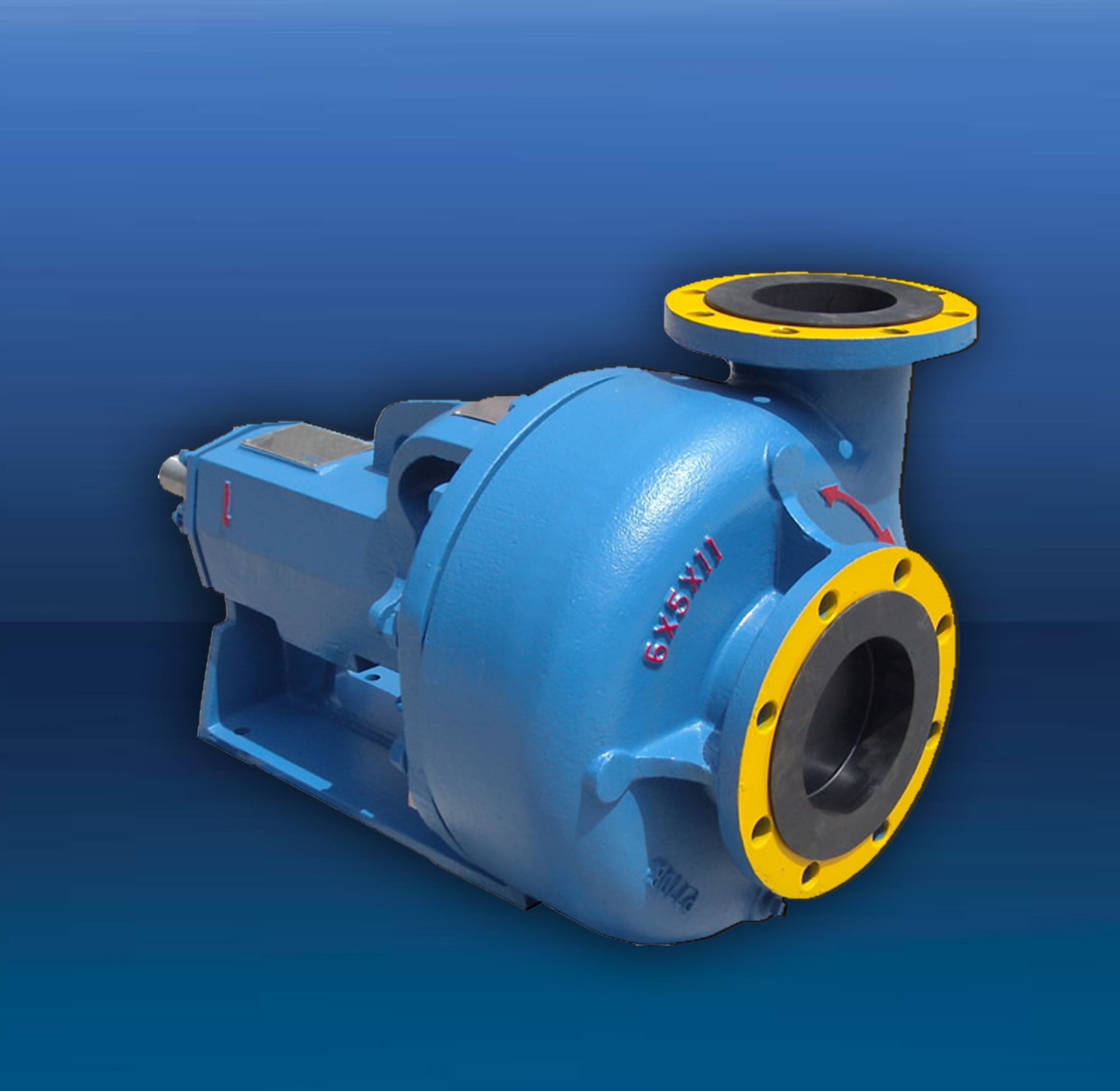
The 2,200-hp mud pump for offshore applications is a single-acting reciprocating triplex mud pump designed for high fluid flow rates, even at low operating speeds, and with a long stroke design. These features reduce the number of load reversals in critical components and increase the life of fluid end parts.
The pump’s critical components are strategically placed to make maintenance and inspection far easier and safer. The two-piece, quick-release piston rod lets you remove the piston without disturbing the liner, minimizing downtime when you’re replacing fluid parts.

I’ve run into several instances of insufficient suction stabilization on rigs where a “standpipe” is installed off the suction manifold. The thought behind this design was to create a gas-over-fluid column for the reciprocating pump and eliminate cavitation.
When the standpipe is installed on the suction manifold’s deadhead side, there’s little opportunity to get fluid into all the cylinders to prevent cavitation. Also, the reciprocating pump and charge pump are not isolated.
The suction stabilizer’s compressible feature is designed to absorb the negative energies and promote smooth fluid flow. As a result, pump isolation is achieved between the charge pump and the reciprocating pump.
The isolation eliminates pump chatter, and because the reciprocating pump’s negative energies never reach the charge pump, the pump’s expendable life is extended.
Investing in suction stabilizers will ensure your pumps operate consistently and efficiently. They can also prevent most challenges related to pressure surges or pulsations in the most difficult piping environments.

A well-placed suction stabilizer can also prevent pump chatter. Pump chatter occurs when energy is exchanged between the quick opening and closing of the reciprocating pump’s valves and the hammer effect from the centrifugal pump. Pump isolation with suction stabilizers is achieved when the charge pumps are isolated from reciprocating pumps and vice versa. The results are a smooth flow of pumped media devoid of agitating energies present in the pumped fluid.
Suction stabilizer units can mitigate most of the challenges related to pulsations or pressure surges, even in the most complex piping conditions. The resulting benefits prevent expensive unplanned downtime and decrease costs and inconvenience associated with system replacements and repairs.

When choosing a size and type of mud pump for your drilling project, there are several factors to consider. These would include not only cost and size of pump that best fits your drilling rig, but also the diameter, depth and hole conditions you are drilling through. I know that this sounds like a lot to consider, but if you are set up the right way before the job starts, you will thank me later.
Recommended practice is to maintain a minimum of 100 to 150 feet per minute of uphole velocity for drill cuttings. Larger diameter wells for irrigation, agriculture or municipalities may violate this rule, because it may not be economically feasible to pump this much mud for the job. Uphole velocity is determined by the flow rate of the mud system, diameter of the borehole and the diameter of the drill pipe. There are many tools, including handbooks, rule of thumb, slide rule calculators and now apps on your handheld device, to calculate velocity. It is always good to remember the time it takes to get the cuttings off the bottom of the well. If you are drilling at 200 feet, then a 100-foot-per-minute velocity means that it would take two minutes to get the cuttings out of the hole. This is always a good reminder of what you are drilling through and how long ago it was that you drilled it. Ground conditions and rock formations are ever changing as you go deeper. Wouldn’t it be nice if they all remained the same?
Centrifugal-style mud pumps are very popular in our industry due to their size and weight, as well as flow rate capacity for an affordable price. There are many models and brands out there, and most of them are very good value. How does a centrifugal mud pump work? The rotation of the impeller accelerates the fluid into the volute or diffuser chamber. The added energy from the acceleration increases the velocity and pressure of the fluid. These pumps are known to be very inefficient. This means that it takes more energy to increase the flow and pressure of the fluid when compared to a piston-style pump. However, you have a significant advantage in flow rates from a centrifugal pump versus a piston pump. If you are drilling deeper wells with heavier cuttings, you will be forced at some point to use a piston-style mud pump. They have much higher efficiencies in transferring the input energy into flow and pressure, therefore resulting in much higher pressure capabilities.
Piston-style mud pumps utilize a piston or plunger that travels back and forth in a chamber known as a cylinder. These pumps are also called “positive displacement” pumps because they literally push the fluid forward. This fluid builds up pressure and forces a spring-loaded valve to open and allow the fluid to escape into the discharge piping of the pump and then down the borehole. Since the expansion process is much smaller (almost insignificant) compared to a centrifugal pump, there is much lower energy loss. Plunger-style pumps can develop upwards of 15,000 psi for well treatments and hydraulic fracturing. Centrifugal pumps, in comparison, usually operate below 300 psi. If you are comparing most drilling pumps, centrifugal pumps operate from 60 to 125 psi and piston pumps operate around 150 to 300 psi. There are many exceptions and special applications for drilling, but these numbers should cover 80 percent of all equipment operating out there.
The restriction of putting a piston-style mud pump onto drilling rigs has always been the physical size and weight to provide adequate flow and pressure to your drilling fluid. Because of this, the industry needed a new solution to this age-old issue.
As the senior design engineer for Ingersoll-Rand’s Deephole Drilling Business Unit, I had the distinct pleasure of working with him and incorporating his Centerline Mud Pump into our drilling rig platforms.
In the late ’90s — and perhaps even earlier — Ingersoll-Rand had tried several times to develop a hydraulic-driven mud pump that would last an acceptable life- and duty-cycle for a well drilling contractor. With all of our resources and design wisdom, we were unable to solve this problem. Not only did Miller provide a solution, thus saving the size and weight of a typical gear-driven mud pump, he also provided a new offering — a mono-cylinder mud pump. This double-acting piston pump provided as much mud flow and pressure as a standard 5 X 6 duplex pump with incredible size and weight savings.
The true innovation was providing the well driller a solution for their mud pump requirements that was the right size and weight to integrate into both existing and new drilling rigs. Regardless of drill rig manufacturer and hydraulic system design, Centerline has provided a mud pump integration on hundreds of customer’s drilling rigs. Both mono-cylinder and duplex-cylinder pumps can fit nicely on the deck, across the frame or even be configured for under-deck mounting. This would not be possible with conventional mud pump designs.
The second generation design for the Centerline Mud Pump is expected later this year, and I believe it will be a true game changer for this industry. It also will open up the application to many other industries that require a heavier-duty cycle for a piston pump application.

There are many different ways to drill a domestic water well. One is what we call the “mud rotary” method. Whether or not this is the desired and/or best method for drilling your well is something more fully explained in this brief summary.
One advantage of drilling with compressed air is that it can tell you when you have encountered groundwater and gives you an indication how much water the borehole is producing. When drilling with water using the mud rotary method, the driller must rely on his interpretation of the borehole cuttings and any changes he can observe in the recirculating fluid. Mud rotary drillers can also use borehole geophysical tools to interpret which zones might be productive enough for your water well.
The mud rotary well drilling method is considered a closed-loop system. That is, the mud is cleaned of its cuttings and then is recirculated back down the borehole. Referring to this drilling method as “mud” is a misnomer, but it is one that has stuck with the industry for many years and most people understand what the term actually means.
The water is carefully mixed with a product that should not be called mud because it is a highly refined and formulated clay product—bentonite. It is added, mixed, and carefully monitored throughout the well drilling process.
The purpose of using a bentonite additive to the water is to form a thin film on the walls of the borehole to seal it and prevent water losses while drilling. This film also helps support the borehole wall from sluffing or caving in because of the hydraulic pressure of the bentonite mixture pressing against it. The objective of the fluid mixture is to carry cuttings from the bottom of the borehole up to the surface, where they drop out or are filtered out of the fluid, so it can be pumped back down the borehole again.
When using the mud rotary method, the driller must have a sump, a tank, or a small pond to hold a few thousand gallons of recirculating fluid. If they can’t dig sumps or small ponds, they must have a mud processing piece of equipment that mechanically screens and removes the sands and gravels from the mixture. This device is called a “shale shaker.”
The driller does not want to pump fine sand through the pump and back down the borehole. To avoid that, the shale shaker uses vibrating screens of various sizes and desanding cones to drop the sand out of the fluid as it flows through the shaker—so that the fluid can be used again.
Some drillers use compressed air to blow off the well, starting at the first screened interval and slowly working their way to the bottom—blowing off all the water standing above the drill pipe and allowing it to recover, and repeating this until the water blown from the well is free of sand and relatively clean. If after repeated cycles of airlift pumping and recovery the driller cannot find any sand in the water, it is time to install a well development pump.
Additional development of the well can be done with a development pump that may be of a higher capacity than what the final installation pump will be. Just as with cycles of airlift pumping of the well, the development pump will be cycled at different flow rates until the maximum capacity of the well can be determined. If the development pump can be operated briefly at a flow rate 50% greater than the permanent pump, the well should not pump sand.
Mud rotary well drillers for decades have found ways to make this particular system work to drill and construct domestic water wells. In some areas, it’s the ideal method to use because of the geologic formations there, while other areas of the country favor air rotary methods.
To learn more about the difference between mud rotary drilling and air rotary drilling, click the video below. The video is part of our “NGWA: Industry Connected” YouTube series:

Pumps tend to be one of the biggest energy consumers in industrial operations. Pump motors, specifically, require a lot of energy. For instance, a 2500 HP triplex pump used for frac jobs can consume almost 2000 kW of power, meaning a full day of fracking can cost several thousand dollars in energy costs alone!
So, naturally, operators should want to maximize energy efficiency to get the most for their money. Even a 1% improvement in efficiency can decrease annual pumping costs by tens of thousands of dollars. The payoff is worth the effort. And if you want to remotely control your pumps, you want to keep efficiency in mind.
In this post, we’ll point you in the right direction and discuss all things related to pump efficiency. We’ll conclude with several tips for how you can maintain pumping efficiency and keep your energy costs down as much as possible.
In simple terms, pump efficiency refers to the ratio of power out to power in. It’s the mechanical power input at the pump shaft, measured in horsepower (HP), compared to the hydraulic power of the liquid output, also measured in HP. For instance, if a pump requires 1000 HP to operate and produces 800 HP of hydraulic power, it would have an efficiency of 80%.
Remember: pumps have to be driven by something, i.e., an electric or diesel motor. True pump system efficiency needs to factor in the efficiency of both the motor AND the pump.
Consequently, we need to think about how electrical power (when using electric motors) or heat power (when using combustion engines) converts into liquid power to really understand pump efficiency.
Good pump efficiency depends, of course, on pump type and size. High-quality pumps that are well-maintained can achieve efficiencies of 90% or higher, while smaller pumps tend to be less efficient. In general, if you take good care of your pumps, you should be able to achieve 70-90% pump efficiency.
Now that we have a better understanding of the pump efficiency metric, let’s talk about how to calculate it. The mechanical power of the pump, or the input power, is a property of the pump itself and will be documented during the pump setup. The output power, or hydraulic power, is calculated as the liquid flow rate multiplied by the "total head" of the system.
IMPORTANT: to calculate true head, you also need to factor in the work the pump does to move fluid from the source. For example, if the source water is below the pump, you need to account for the extra work the pump puts in to draw source water upwards.
*Note - this calculation assumes the pump inlet is not pressurized and that friction losses are minimal. If the pump experiences a non-zero suction pressure, or if there is significant friction caused by the distance or material of the pipe, these should be factored in as well.
Every foot of water creates an additional 0.434 PSI of pressure, so we"ll find the elevation head by converting the change in elevation in feet to the suction pressure created by the water.
You"ll notice that the elevation head is minimal compared to the discharge pressure, and has minimal effect on the efficiency of the pump. As the elevation change increases or the discharge pressure decreases, however, elevation change will have a greater impact on total head.
Obviously, that’s a fair amount of math to get at the pump efficiency, considering all of the units conversions that need to be done. To avoid doing these calculations manually, feel free to use our simple pump efficiency calculator.
Our calculations use static variables (pump-rated horsepower and water source elevation) and dynamic variables (discharge flow and pressure). To determine pump efficiency, we need to measure the static variables only once, unless they change.
If you want to measure the true efficiency of your pump, taking energy consumption into account, you could add an electrical meter. Your meter should consist of a current transducer and voltage monitor (if using DC) for electrical motors or a fuel gauge for combustion. This would give you a true understanding of how pump efficiency affects energy consumption, and ultimately your bank account.
Up until this point, we’ve covered the ins and outs of how to determine pump efficiency. We’re now ready for the exciting stuff - how to improve pump efficiency!
One of the easiest ways to improve pump efficiency is to actually monitor pumps for signs of efficiency loss! If you monitor flow rate and discharge (output power) along with motor current or fuel consumption, you’ll notice efficiency losses as soon as they occur. Simply having pump efficiency information on hand empowers you to take action.
Another way to increase efficiency is to keep pumps well-maintained. Efficiency losses mostly come from mechanical defects in pumps, e.g., friction, leakages, and component failures. You can mitigate these issues through regular maintenance that keeps parts in working order and reveals impending failures. Of course, if you are continuously monitoring your pumps for efficiency drops, you’ll know exactly when maintenance is due.
You can also improve pump efficiency by keeping pumps lubricated at all times. Lubrication is the enemy of friction, which is the enemy of efficiency (“the enemy of my enemy is my friend…”).
A fourth way to enhance pump efficiency is to ensure your pumps and piping are sized properly for your infrastructure. Although we’re bringing this up last, it’s really the first step in any pumping operation. If your pumps and piping don’t match, no amount of lubricant or maintenance will help.
Pipes have physical limits to how much fluid they can move at a particular pressure. If pipes aren’t sized properly, you’ll lose efficiency because your motor will have to work harder. It’s like air conditioning - if your ductwork isn’t sized appropriately for your home, you’ll end up paying more on your energy bill.
In this post, we’ve given you the full rundown when it comes to calculating and improving pump efficiency. You can now calculate, measure, and improve pump efficiency, potentially saving your business thousands of dollars annually on energy costs.
For those just getting started with pump optimization, we offer purpose-built, prepackaged solutions that will have you monitoring pump efficiency in minutes, even in hazardous environments.

A kick is a well control problem in which the pressure found within the drilled rock is higher than the mud hydrostatic pressure acting on the borehole or rock face. When this occurs, the greater formation pressure has a tendency to force formation fluids into the wellbore. This forced fluid flow is called a kick. If the flow is successfully controlled, the kick is considered to have been killed. An uncontrolled kick that increases in severity may result in what is known as a “blowout.”
Yet another factor affecting kick severity is the “pressure differential” involved. Pressure differential is the difference between the formation fluid pressure and the mud hydrostatic pressure. If the formation pressure is much greater than the hydrostatic pressure, a large negative differential pressure exists. If this negative differential pressure is coupled with high permeability and high porosity, a severe kick may occur.
Another way of labeling kicks is by identifying the required mud weight increase necessary to control the well and kill a potential blowout. For example, if a kick required a 0.7-lbm/gal (84-kg/m3) mud weight increase to control the well, the kick could be termed a 0.7-lbm/gal (84-kg/m3) kick. It is interesting to note that an average kick requires approximately 0.5 lbm/gal (60 kg/m3), or less, mud weight increase.
Kicks occur as a result of formation pressure being greater than mud hydrostatic pressure, which causes fluids to flow from the formation into the wellbore. In almost all drilling operations, the operator attempts to maintain a hydrostatic pressure greater than formation pressure and, thus, prevent kicks; however, on occasion the formation will exceed the mud pressure and a kick will occur. Reasons for this imbalance explain the key causes of kicks:
Insufficient mud weight is the predominant cause of kicks. A permeable zone is drilled while using a mud weight that exerts less pressure than the formation pressure within the zone. Because the formation pressure exceeds the wellbore pressure, fluids begin to flow from the formation into the wellbore and the kick occurs.
These abnormal formation pressures are often associated with causes for kicks. Abnormal formation pressures are greater pressures than in normal conditions. In well control situations, formation pressures greater than normal are the biggest concern. Because a normal formation pressure is equal to a full column of native water, abnormally pressured formations exert more pressure than a full water column. If abnormally pressured formations are encountered while drilling with mud weights insufficient to control the zone, a potential kick situation has developed. Whether or not the kick occurs depends on the permeability and porosity of the rock. A number of abnormal pressure indicators can be used to estimate formation pressures so that kicks caused by insufficient mud weight are prevented (some are listed in Table 1).
An obvious solution to kicks caused by insufficient mud weights seems to be drilling with high mud weights; however, this is not always a viable solution. First, high mud weights may exceed the fracture mud weight of the formation and induce lost circulation. Second, mud weights in excess of the formation pressure may significantly reduce the penetration rates. Also, pipe sticking becomes a serious consideration when excessive mud weights are used. The best solution is to maintain a mud weight slightly greater than formation pressure until the mud weight begins to approach the fracture mud weight and, thus, requires an additional string of casing.
Improperly filling up of the hole during trips is another prominent cause of kicks. As the drillpipe is pulled out of the hole, the mud level falls because the pipe steel no longer displaces the mud. As the overall mud level decreases, the hole must be periodically filled up with mud to avoid reducing the hydrostatic pressure and, thereby, allowing a kick to occur.
Several methods can be used to fill up the hole, but each must be able to accurately measure the amount of mud required. It is not acceptable—under any condition—to allow a centrifugal pump to continuously fill up the hole from the suction pit because accurate mud-volume measurement with this sort of pump is impossible. The two acceptable methods most commonly used to maintain hole fill-up are the trip-tank method and the pump-stroke measurements method.
The trip-tank method has a calibration device that monitors the volume of mud entering the hole. The tank can be placed above the preventer to allow gravity to force mud into the annulus, or a centrifugal pump may pump mud into the annulus with the overflow returning to the trip tank. The advantages of the trip-tank method include that the hole remains full at all times, and an accurate measurement of the mud entering the hole is possible.
The other method of keeping a full hole—the pump-stroke measurement method—is to periodically fill up the hole with a positive-displacement pump. A flowline device can be installed with the positive-displacement pump to measure the pump strokes required to fill the hole. This device will automatically shut off the pump when the hole is full.
Pulling the drillstring from the borehole creates swab pressures. Swab pressures are negative, and reduce the effective hydrostatic pressure throughout the hole and below the bit. If this pressure reduction lowers the effective hydrostatic pressure below the formation pressure, a potential kick has developed. Variables controlling swab pressures are:
Gas-contaminated mud will occasionally cause a kick, although this is rare. The mud density reduction is usually caused by fluids from the core volume being cut and released into the mud system. As the gas is circulated to the surface, it expands and may reduce the overall hydrostatic pressure sufficient enough to allow a kick to occur.
Although the mud weight is cut severely at the surface, the hydrostatic pressure is not reduced significantly because most gas expansion occurs near the surface and not at the hole bottom.
Occasionally, kicks are caused by lost circulation. A decreased hydrostatic pressure occurs from a shorter mud column. When a kick occurs from lost circulation, the problem may become severe. A large volume of kick fluid may enter the hole before the rising mud level is observed at the surface. It is recommended that the hole be filled with some type of fluid to monitor fluid levels if lost circulation occurs.
An increase in flow rate leaving the well, while pumping at a constant rate, is a primary kick indicator. The increased flow rate is interpreted as the formation aiding the rig pumps by moving fluid up the annulus and forcing formation fluids into the wellbore.
If the pit volume is not changed as a result of surface-controlled actions, an increase indicates a kick is occurring. Fluids entering the wellbore displace an equal volume of mud at the flowline, resulting in pit gain.
When the rig pumps are not moving the mud, a continued flow from the well indicates a kick is in progress. An exception is when the mud in the drillpipe is considerably heavier than in the annulus, such as in the case of a slug.
A pump pressure change may indicate a kick. Initial fluid entry into the borehole may cause the mud to flocculate and temporarily increase the pump pressure. As the flow continues, the low-density influx will displace heavier drilling fluids, and the pump pressure may begin to decrease. As the fluid in the annulus becomes less dense, the mud in the drillpipe tends to fall and pump speed may increase.
Other drilling problems may also exhibit these signs. A hole in the pipe, called a “washout,” will cause pump pressure to decrease. A twist-off of the drillstring will give the same signs. It is proper procedure, however, to check for a kick if these signs are observed.
When the drillstring is pulled out of the hole, the mud level should decrease by a volume equivalent to the removed steel. If the hole does not require the calculated volume of mud to bring the mud level back to the surface, it is assumed a kick fluid has entered the hole and partially filled the displacement volume of the drillstring. Even though gas or salt water may have entered the hole, the well may not flow until enough fluid has entered to reduce the hydrostatic pressure below the formation pressure.
Drilling fluid provides a buoyant effect to the drillstring and reduces the actual pipe weight supported by the derrick. Heavier muds have a greater buoyant force than less dense muds. When a kick occurs, and low-density formation fluids begin to enter the borehole, the buoyant force of the mud system is reduced, and the string weight observed at the surface begins to increase.
An abrupt increase in bit-penetration rate, called a “drilling break,” is a warning sign of a potential kick. A gradual increase in penetration rate is an abnormal pressure indicator, and should not be misconstrued as an abrupt rate increase.
Fortunately, the lower mud weights from the cuttings effect are found near the surface (generally because of gas expansion), and do not appreciably reduce mud density throughout the hole. Table 3 shows that gas cutting has a very small effect on bottomhole hydrostatic pressure.
An important point to remember about gas cutting is that, if the well did not kick within the time required to drill the gas zone and circulate the gas to the surface, only a small possibility exists that it will kick. Generally, gas cutting indicates that a formation has been drilled that contains gas. It does not mean that the mud weight must be increased.
Drilling-efficiency data, such as downhole weight on bit and torque, can be used to differentiate between rate of penetration changes caused by drag and those caused by formation strength. Monitoring bottomhole pressure, temperature, and flow with the MWD tool is not only useful for early kick detection, but can also be valuable during a well-control kill operation. Formation evaluation capabilities, such as gamma ray and resistivity measurements, can be used to detect influxes into the wellbore, identify rock lithology, and predict pore pressure trends.
The MWD tool enables monitoring of the acoustic properties of the annulus for early gas-influx detection. Pressure pulses generated by the MWD pulser are recorded and compared at the standpipe and the top of the annulus. Full-scale testing has shown that the presence of free gas in the annulus is detected by amplitude attenuation and phase delay between the two signals. For water-based mud systems, this technique has demonstrated the capacity to consistently detect gas influxes within minutes before significant expansion occurs. Further development is currently under way to improve the system’s capability to detect gas influxes in oil-based mud.
Some MWD tools feature kick detection through ultrasonic sensors. In these systems, an ultrasonic transducer emits a signal that is reflected off the formation and back to the sensor. Small quantities of free gas significantly alter the acoustic impedance of the mud. Automatic monitoring of these signals permits detection of gas in the annulus. It should be noted that these devices only detect the presence of gas at or below the MWD tool.
where gi = influx gradient, psi/ft; gmdp = mud gradient in drillpipe, psi/ft; and hi = influx height, ft. The influx gradient can be evaluated using the guidelines in Table 1.
It is necessary to calculate the mud weight needed to balance bottomhole formation pressure. “Kill-weight mud” is the amount of mud necessary to exactly balance formation pressure. It will be later shown that it is safer to use the exact required mud weight without variation
Because the drillpipe pressure has been defined as a bottomhole pressure gauge, the psidp can be used to calculate the mud weight necessary to kill the well. The kill mud formula follows:
Because the casing pressure does not appear in Eq. 2, a high casing pressure does not necessarily indicate a high kill-weight mud. The same is true for pit gain because it does not appear in Eq. 2. Example 1 uses the kill-weight mud formula.
Nas, S. 2011. Kick Detection and Well Control in a Closed Wellbore. IADC/SPE Managed Pressure Drilling and Underbalanced Operations Conference and Exhibition, 5–6 April 2011, Denver, Colorado, USA. SPE-143099-MS. http://dx.doi.org/143099-MS
Low, E. and Jansen, C. 1993. A Method for Handling Gas Kicks Safely in High-Pressure Wells. Journal of Petroleum Technology 45:6 SPE-21964-PA. http://dx.doi.org/10.2118/21964-PA
Hornung, M.R. 1990. Kick Prevention, Detection, and Control: Planning and Training Guidelines for Drilling Deep High-Pressure Gas Wells. SPE/IADC Drilling Conference, 27 February-2 March 1990, Houston, Texas. SPE-19990-MS. http://dx.doi.org/10.2118/19990-MS

When two (or more) pumps are arranged in serial their resulting pump performance curve is obtained by adding theirheads at the same flow rate as indicated in the figure below.
Centrifugal pumps in series are used to overcome larger system head loss than one pump can handle alone. for two identical pumps in series the head will be twice the head of a single pump at the same flow rate - as indicated with point 2.
With a constant flowrate the combined head moves from 1 to 2 - BUTin practice the combined head and flow rate moves along the system curve to point 3. point 3 is where the system operates with both pumps running
When two or more pumps are arranged in parallel their resulting performance curve is obtained by adding the pumps flow rates at the same head as indicated in the figure below.
Centrifugal pumps in parallel are used to overcome larger volume flows than one pump can handle alone. for two identical pumps in parallel and the head kept constant - the flow rate doubles compared to a single pump as indicated with point 2
Note! In practice the combined head and volume flow moves along the system curve as indicated from 1 to 3. point 3 is where the system operates with both pumps running
In practice, if one of the pumps in parallel or series stops, the operation point moves along the system resistance curve from point 3 to point 1 - the head and flow rate are decreased.


 8613371530291