
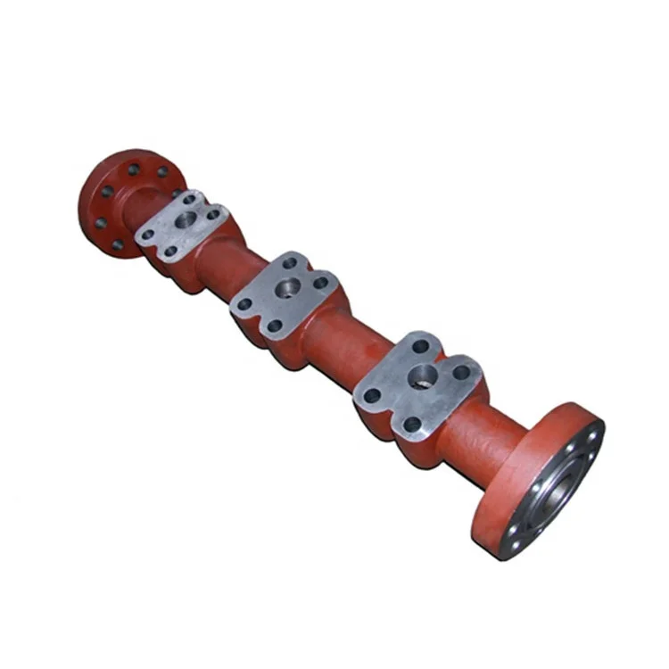
mud pump suction manifold free sample

Explore a wide variety of mud pump suction manifold on Alibaba.com and enjoy exquisite deals. The machines help maintain drilling mud circulation throughout the project. There are many models and brands available, each with outstanding value. These mud pump suction manifold are efficient, durable, and completely waterproof. They are designed to lift water and mud with efficiency without using much energy or taking a lot of space.
The primary advantage of these mud pump suction manifold is that they can raise water from greater depths. With the fast-changing technology, purchase machines that come with the best technology for optimum results. They should be well adapted to the overall configuration of the installation to perform various operations. Hence, quality products are needed for more efficiency and enjoyment of the machines" full life expectancy.
Alibaba.com offers a wide selection of products with innovative features. The products are designed for a wide range of flow rates that differ by brand. They provide cost-effective options catering to different consumer needs. When choosing the right mud pump suction manifold for the drilling project, consider factors such as size, shape, and machine cost. More powerful tools are needed when dealing with large projects such as agriculture or irrigation.
Alibaba.com provides a wide range of mud pump suction manifold to suit different tastes and budgets. The site has a large assortment of products from major suppliers on the market. The products are made of durable materials to avoid corrosion and premature wear during operations. The range of products and brands on the site assures quality and good value for money.
I’ve run into several instances of insufficient suction stabilization on rigs where a “standpipe” is installed off the suction manifold. The thought behind this design was to create a gas-over-fluid column for the reciprocating pump and eliminate cavitation.
When the standpipe is installed on the suction manifold’s deadhead side, there’s little opportunity to get fluid into all the cylinders to prevent cavitation. Also, the reciprocating pump and charge pump are not isolated.
Installing a suction stabilizer from the suction manifold port supports the manifold’s capacity to pull adequate fluid and eliminates the chance of manifold fluid deficiency, which ultimately prevents cavitation.
Another benefit of installing a suction stabilizer is eliminating the negative energies in fluids caused by the water hammer effect from valves quickly closing and opening.
The suction stabilizer’s compressible feature is designed to absorb the negative energies and promote smooth fluid flow. As a result, pump isolation is achieved between the charge pump and the reciprocating pump.
The isolation eliminates pump chatter, and because the reciprocating pump’s negative energies never reach the charge pump, the pump’s expendable life is extended.
Investing in suction stabilizers will ensure your pumps operate consistently and efficiently. They can also prevent most challenges related to pressure surges or pulsations in the most difficult piping environments.
Sigma Drilling Technologies’ Charge Free Suction Stabilizer is recommended for installation. If rigs have gas-charged cartridges installed in the suction stabilizers on the rig, another suggested upgrade is the Charge Free Conversion Kits.

This application is a continuation of pending U.S. patent Ser. No. 12/220,876 entitled “A Reinforced Smart Mud Pump” which take priority to provisional application for patent filed Jul. 30, 2007 bearing Ser. No. 60/962,637 and is incorporated by reference herein as if fully set forth.
This invention relates generally to the field of mud pumps and more specifically to a reinforced smart mud pump. Mud pumps that use piston displacement, produce imposed forces that cause wear and tear on various pump components, including pump cross head piping, cylinders, inlet and discharge valves, seal components including piston or plunger seals, the pump cylinder block or so-called fluid end, and other components. There has been a need to provide increased longevity and performance for such pumps and to determine if deteriorations in pump performance are occurring, to analyze the source of decreased performance and to further real time control and data to monitor and in some cases change the operating characteristics before damage occurs to the pump. The use of greatly strengthened components in combination with a computer controlled system integrated with a real time monitored and controlled reset relief valve may be integrated into an oilfield application to prevent catastrophic pump failure and extend pump life.
Pump operating characteristics often have a deleterious effect on pump performance. For example, delayed valve closing and sealing can result in loss of volumetric efficiency. Factors affecting pump valve performance include fluid properties, valve spring design and fatigue life, valve design and the design of the cylinder or fluid end housing. Delayed valve response also causes a higher pump chamber pressure than normal which in turn may cause overloads on pump mechanical components, including the pump crankshaft or eccentric and its bearings, speed reduction gearing, the pump drive shaft and the pump prime mover. Moreover, increased fluid acceleration induced pressure “spikes” in the pump suction and discharge flowstreams can be deleterious. Fluid properties are also subject to analysis to determine compressibility, the existence of entrained gases in the pump fluid stream, susceptibility to cavitation and the affect of pump cylinder or fluid end design on fluid properties and vice versa.
Still further, piston or plunger seal or packing leaking can result in increased delay of pump discharge valve opening with increased hydraulic flow and acceleration induced hydraulic forces imposed on the pump and its discharge piping. Moreover, proper sizing and setup of pulsation control equipment is important to the efficiency and long life of a pump system. Pulsation control equipment location and type can also affect pump performance as well as the piping system connected to the pump
In prior art, the control of a mud pump has been disclosed focused on piston position for acquiring information about the pump and its performance characteristics. For example, U.S. Pat. No. 6,882,960 to Miller, shows a system for monitoring and analyzing performance parameters of reciprocating piston, or power pumps and associated piping systems. This patent fails to disclose the innovative aspects of the present invention.
Nothing in the prior art shows a computer integrated mud pump with significant strengthening features that increase the life cycle of a pump in the manner of the present invention with real time control of significant operating functions and feedback from various sensors and reset relief valves.
Another advantage of the invention is to provide a mud pump that utilizes transducers in line with the ambient pressure in conjunction with a computer controlled pressure relief valve to record and monitor pump characteristics and control the pump to prevent catastrophic failure.
Another advantage of the invention is to provide a mud pump that transmits data to a computer for later analysis of important operating characteristics.
A further advantage of the invention is to provide a mud pump that can be controlled during its operation to prevent certain damaging events to the pump or underlying pressurized system.
In accordance with a preferred embodiment of the invention, there is shown a pump system for movement of fluids having a reciprocating piston power pump having at least three reciprocating pistons operable to displace fluid from a housing having a pumping chamber, an integrally forged crankshaft operably connected to the pistons, at least one sensor operable to sense ambient conditions on the pump, and a computer control for processing data from the sensor to regulate the operation of the pump in response to the data.
In accordance with a preferred embodiment of the invention, there is shown a pump system for movement of fluids having a reciprocating piston power pump having at least three reciprocating pistons operable to displace fluid from a housing having a pumping chamber, an integrally forged crankshaft operably connected to the pistons, polyflorocarbon infused treatement applied to at least one crosshead and one crosshead slide in the system, and at least one sensor operable to sense ambient conditions on the pump.
In accordance with a preferred embodiment of the invention, there is shown a pump system for movement of fluids having a reciprocating piston power pump having at least three reciprocating pistons operable to displace fluid from a housing having a pumping chamber, an integrally forged crankshaft operably connected to the pistons, at least one sensor operable to sense ambient conditions on the pump, a computer control for processing data from the sensor to regulate the operation of the pump in response to the data; and pressure sensors for monitoring fluid pressure operably connected to the computer control. In addition, upper and lower limits to temperature, vibration and pressure can be set. Further, in a preferred embodiment, all lubrication and water pumps must be on before the control system will permit unit to be operated.
In a preferred embodiment of the present invention, there is shown a reciprocating plunger or piston power pump. The pump includes additional features not found in conventional reciprocal pumps as heretofore described. The basic operation of the pump is similar to a triplex plunger pump configured to reciprocate three spaced apart plungers or pistons, which are connected by suitable connecting rod and crosshead mechanisms, to a rotatable crankshaft or eccentric. FIG. 1 shows a side view of the pump and auxiliary equipment according to a preferred embodiment of the invention. Pump housing 100 covers the internal pump components and allows for a variety of conventional means to move the rotatable crankshaft 114 such as an electric motor 102 and belt drive 104. Within pump housing 100 may be disposed a pressurized lubrication spraying system that continuously feeds lubricant such as oil around the crankshaft and associated internal pump components.
A suction module 104 of conventional design houses each plunger which operates each section of the triplex plunger pump. A pressure relief valve mount 110 allows for attachment of a reset relief valve (show in FIG. 5) to at least one suction module 106 in a system for pumping drilling mud composed of water, clay and chemical additives, down through the inside of a drill pipe of an oil well drilling operation. The drilling mud is pumped at very high pressure so the mud is forced out through a bit at the lower end of the drill pipe and returned to the surface, carrying rock cuttings from the well. In this illustrative example the drilling mud from the pump system is fed into the attached vessel 112 sometimes known as a dumping ball. In a preferred embodiment all components are installed on a full unitized skid 120 providing room for motors, starters, sheaves, belts and any associated test equipment and a solid platform for installation of bracing 122 for component parts. Vessel 112 smoothes out the pulsation caused by the pumping action of the system to deliver pumped fluid out of port 115 in a more controlled manner.
With the use of computer modeling, high technology engineering, metallurgical and mechanical enhancements, the smart pump is revolutionary in design. The pump is manufactured using advanced materials and techniques including an integrally forged and balanced crank. This provides significant strength advantages and increases the life cycle of the pump. Unlike prior art pump systems, the crank is not a porous unbalanced crank casting, nor is it a fabricated with separate plates and bars and later welded together. As shown in FIG. 2 the crank 200 is fabricated from an integrally forged single ingot by the open hammer forging process resulting in a single piece with no welding or pinning of multiple pieces. A connecting rod 202 for each plunger is attached to the crank 200 such that the crank freely rotates and creates a reciprocating action in each connecting rod 202 attached to the crank 200. A crosshead 204 and crosshead slide 206 attach to each connector rod to help retain engine oil in the crankcase. A plunger connection 210 at each connector rod 202 end provides a means of attachment for a variety of rod and plunger components.
All of the ground crossheads 204 and honed crosshead slides 206 are treated with a polyflorocarbon coating for more lubricity and wear performance characteristics resulting in 15% less energy cost. This process has been used in the racing industry with much higher performance results. The poly-fluorocarbon coating is applied to each crosshead and slide and helps retain engine oil on the component surfaces during intense heat and extreme pressure. The oil is essentially absorbed into each crosshead 204 and slide 206 in such a way as to increase their lubricity. The crosshead 204 center line alignment is laser monitored for even wear. In a preferred embodiment of the invention the pump uses suction modules, discharge modules and discharge manifold and a double helical gear set. All gear sets are prepared with mesh test providing contact tapes accompanied by digitals to AGMS 11+ standards. All gear sets are further preferably chemically treated to 0.4 RMS or better to exponentially increase bearing life.
In the present invention, the crankshaft is a integrally forged piece to increase its operating strength significantly, and is an integral part of the crank 200. The terms crank 200 and crankshaft are used interchangably although in conventional pumps and engines the crank 200 and crankshaft may comprise separate components. Turning again to FIG. 1 we see the crankshaft includes a rotatable input shaft portion adapted to be operably connected to a suitable prime mover, such as an internal combustion engine or electric motor 102, as an exemplary installation. The crankshaft is mounted in a suitable, so-called power end housing 114 which is connected to a fluid end structure configured to have a plurality of pumping chambers, in this example, three separate pumping chambers exposed to their respective plungers or pistons. Plungers refer to the rod, rod joints and piston end portions of the plunger unless otherwise specified.
FIG. 3 shows a partial cutaway side view of the pump according to a preferred embodiment of the invention. The fluid end comprises a housing having the series of plural cavities or chambers for receiving fluid from an inlet manifold by way of conventional poppet type inlet or suction valves contained each suction module 300. The piston or plunger 304 projects at one end into the chamber and is connected to a suitable crosshead mechanism 306, including a crosshead extension. The crosshead extension is operably connected to the crankshaft using connecting rods 308 as described above. Each plunger 306 projects through a conventional packing 310 or plunger 306 seal. Each chamber for each plunger 306 is operably connected to a discharge piping manifold by way of a suitable discharge valve. Valves may be of a variety of conventional designs and are typically spring biased to their closed positions. Valves may also include or are associated with removable valve seat members. Each valve may also have a seal member formed thereon engageable with the associated valve seat to provide fluid sealing when the valves are in their respective closed and seat engaging positions. A unique feature of a preferred embodiment of the the smart pump is a positive air pressure plunger seal 312 to prevent leakage and prevent wear on the plunger. FIG. 3A shows a cross sectional view of the positive air pressure plunger seal about a synchronized plunger according to a preferred embodiment of the invention. As the plunger 350 moves reciprocally, pressurized air is introduced into through seal 352 through a plurality of pressurized air ports 354 preventing fluid leakage from the plunger 350 end which engages and moves drilling mud through the aforementioned valves. The pressurized air flow 356 isolates any material from scoring and etching the plunger 350 and reduces friction between the seal wall and the plunger 350.
In a preferred embodiment the pump may be fitted with a P-QUIP ® fluid end systems including P-QUIP ® kwik clamp liner retentions system, P-QUIP ® kwik rod system and cover system. The P-QUIP ® kwik-clamp valve and strainer cover retention system has a very fast and safe access with much reduced down time and LTAs (Lost Time Accidents) due to mishaps. Hammers or cheater bars are not required and the system includes an automatic clamping means which results in no more under or over tightening—caps will not loosen off in use. This all results in easy installation and easy operation with conventional air or hand operated hydraulic pump. Like the Liner Retention System, the valve and strainer covers are sealed firmly in the fluid end by means of a spring mechanism. Similarly, the outer cover is removed when the clamping force is released by means of the hydraulic pump. This system heightens safety as it is no longer necessary to tighten OEM type threaded cap retainers by hammer.
The P-QUIP ® kwik rod system allows for fast and safe piston changes and is constructed of 17.4 PH martensitic high-resistance stainless steel, eliminating corrosion. Three piece rod system is held together using pins, which eliminates prior systems and clamp type systems. The P-QUIP ® kwik cover system allows for fast and save valve access changes with no hammers or cheater bars. The cover offers a positive retention force against the plug eliminating the need for retightening. The P-Quip ® kwik rod pump rod system permits fast and safe piston changes resulting in reduced down time. There is no need for heavy clamps or connecting threads and studs. The clamping force is automatically controlled resulting in no broken rod ends. Due to its construction, its self alignment facility gives improved piston and liner life. There are no corrosion problems as all parts are stainless steel, including hard-surfaced stainless steel power end rods. It has an integral liner flushing systems.
On conventional mud-pump rod systems, the rod is held together by means of taper clamps and screw threads which are slow and awkward to assemble correctly and readily wear out. Due to their design, the clamps obscure vision of the rod joints, preventing a check being made that the rod is correctly aligned. Uneven loads are imposed on the flanged rod ends, resulting in premature failure.
The P-QUIP ® Kwik-Rod system avoids these problems as the rod components are held together by powerful spring-loaded ends on a release link in the center of the rod assembly. The ends of the release link are attached to the pony rod and piston rod by means of high tensile stainless steel pins held in shear. The shear force is very quickly and easily released by a few strokes of a small hydraulic pump.
Dismantling and re-assembly of the complete rod system takes under one minute. Furthermore, there are no flanged joints on the rods to chip, wear or break. Hence, rod life is enhanced and, because rod alignment is readily achieved, significantly improved swab and liner life is generally obtained. FIG. 4 shows a partial cutaway overhead of the pump housing according to a preferred embodiment of the invention. Plunger rods 400 are synchronized based on the crank speed and can be checked for alignment as described herein. In a preferred embodiment, a viewing port 402 or access cover allows access to plunger rods 400 for alignment and maintenance.
Further enhancement to the pump is achieved by use of ductile iron for the crossheads, the crosshead slides and the connecting rods. The connecting rods are solid ductile iron which reduces their elongation during setoff to zero. The typical rod experiences stretching or elongation during set-off when the relief valve is activated. The benefit of ductile iron in increased strength and higher tensile strength. All the major components, the crank, the crossheads, the slides and the rods by use of mettalurgical engineering are designed to bring the pump tensile strength up to 200,000 p.s.i.
The pump is network and web based with a data acquisition system to monitor pump performance and constantly evaluate pump valve dynamics. Pressure transducers are located in pump chambers used to determine valve sealing delays, fluid compression delays, chamber overshoot pressure, crosshead loading shock forces and chamber volumetric efficiency. Pressure transducers are also located in suction piping and manifolds and discharge piping and manifold. Temperature is similarly monitored for fluid temperature for mud properties and power end lubrication. Further, there is real time power input data to calculate system mechanical efficiency.
Those skilled in the art will recognize that the present invention may be utilized with a wide variety of single and multi-cylinder reciprocating piston power pumps as well as possibly other types of positive displacement pumps. However, the system and method of the invention are particularly useful for analysis of reciprocating piston or plunger type pumps. Moreover, the number of cylinders of such pumps may vary substantially between a single cylinder and essentially any number of cylinders or separate pumping chambers and the illustration of a so called triplex or three cylinder pump is exemplary.
The performance analysis system of the invention is characterized, in part, by a digital signal processor which is operably connected to a plurality of sensors via suitable conductor means well known in the art. The processor may be of a type commercially available as previously described and may wireless remote and other control options associated therewith. The processor is operable to receive signals from a power input sensor which may comprise a torque meter or other type of power input sensor. Power end crankcase oil temperature may be measured by a sensor. Crankshaft and piston position may be measured by a non-intrusive sensor including a beam interrupter mountable on a pump crosshead extension for interrupting a light beam provided by a suitable light source or optical switch.
A vibration sensor may be mounted on the power end or on the discharge piping or manifold for sensing vibrations generated by the pump. Suitable pressure sensors are adapted to sense pressures at numerous locations, including the inlet piping and manifolds. Other pressure sensors may sense pressures in the pumping chambers of the respective plungers or pistons. Other pressure sensors sense pressures upstream and downstream of a discharge pulsation dampener. Still further, a fluid temperature sensor may be mounted on discharge manifold or piping to sense the discharge temperature of the working fluid. Fluid temperature may also be sensed at the inlet or suction manifold.
Pump performance analysis using the system may require all or part of the sensors described above, as those skilled in the art will understand and appreciate from the description which follows. The processor may be connected to a terminal or further processor, including a display unit or monitor mounted in a housing connected to the pump system and main housing. Still further, the processor may be connected to a signal transmitting network, such as the Internet, or a local network.
FIG. 4A shows a schematic drawing of a representative computer controlled monitoring system. A computer 450 receives input from from sensors 452 and modules 454 in the pump system and uses software algorithyms to analyze pump performance, record and display operational data on a visual screen display 456. The computer controlled monitoring system may be adapted to provide a wide array of graphic displays and data associated with the performance of a power pump on a real time or replay basis. A substantial amount of information is available including pump identification (Pump ID) crankshaft speed, fluid flow rate, time lapse since the beginning of the display, starting date and starting time and scan rate. The display 456 displays discharge piping operating pressure, peak-to-peak pressures, fluid flow rate induced peak-to-peak pressure, fluid flow induced peak-to-peak pressure as a percentage of average operating pressure, pump volumetric efficiency and pump mechanical efficiency. The display 456 also indicates discharge valve seal delay in degrees of rotation of the crankshaft from a so called piston zero or top dead center (maximum displacement) starting point with respect to the respective cylinder chambers of the pump, as well as piston seal pressure variation during fluid compression and suction valve seal delay in degrees of rotation of the crankshaft or eccentric from the top dead center position of the respective cylinder chambers. Still further, the pump type may be displayed as well as suction piping pressures, as indicated. The parameters displayed are determined by the system of the invention which utilizes the various sensors.
Various pressure sensors 452 sense pressure in the respective pump chambers associated with each of the pistons and pressure signals are transmitted to the processor. These pressure signals may indicate when valves are opening and closing. For example, if the pressure sensed in a pump chamber does not rise essentially instantly, after the piston for that chamber passes bottom dead center by 0 degrees to 10 degrees of crankshaft rotation, then it is indicated that the inlet or suction valve is delayed in closing or is leaking. In situations like this, the display may show that a discharge valve is not closed for 16.7 degrees of rotation after piston top dead center position. Accordingly, pressure changes, or the lack thereof, are sensed by cylinder chamber pressure sensors.
Software embedded in the computer 450 processor is operable to correlate the angle of rotation of the crankshaft with respect to pressure sensed in the respective cylinder chambers to determine any delay in pressure changes which could be attributable to delays in the respective suction or discharge valves reaching their fully seated and sealed positions. These delays can, of course, affect volumetric efficiency of the respective cylinder chambers and the overall volumetric efficiency of the pump. In this regard, total volumetric efficiency is determined by calculating the average volumetric efficiency based on the angular delay in chamber pressure increase or pressure decrease, as the case may be, with respect to the position of the pistons in the respective chambers.
The volumetric efficiency of the pump is a combination of normal pump timed events and the sealing condition of the piston seal and the inlet and discharge valves. Pump volumetric efficiency and component status is determined by determining the condition of the components and calculating the degree of fluid bypass. Pump volumetric efficiency (VE) is computed by performing a computational fluid material balance around each pump chamber.
Pump chamber pressures, as sensed by the sensors may be used to determine pump timing events that affect performance, such as volumetric efficiency, and chamber maximum and minimum pressures, as well as fluid compression delays. Still further, fluid pressures in the pump chambers may be sensed during a discharge stroke to determine, through variations in pressure, whether or not there is leakage of a piston packing or seal, such as the packing seal. Still further, maximum and minimum chamber fluid pressures may be used to determine fatigue limits for certain components of a pump, such as the fluid end housing, the valves and virtually any component that is subject to cyclic stresses induced by changes in pressure in the pump chambers and the pump discharge piping.
As mentioned previously, the computer 450 processor may be adapted with a suitable computer program to provide for determining pump volumetric efficiency which is the arithmetic average of the volumetric efficiency of the individual pump chambers as determined by the onset of pressure rise as a function of crankshaft position (delay in suction valve closing and seating) and the delay in pressure drop after a piston has reached top dead center (delay in discharge valve closing and seating).
Additional parameters which may be measured and calculated in accordance with the invention are the so-called delta volumes for the suction or inlet stabilizer and the discharge pulsation dampener. The delta volume is the volume of fluid that must be stored and then returned to the fluid flowstream to make the pump suction and discharge fluid flow rate substantially constant. This volume varies as certain pump operating parameters change. A significant increase in delta volume occurs when timing delays are introduced in the opening and closing of the suction and discharge valves. The delta volume is determined by applying actual angular degrees of rotation of the crankshaft with respect the suction and discharge valve closure delays to a mathematical model that integrates the difference between the actual fluid flow rate and the average flow rate.
Another parameter associated with determining component life for a pump, is pump hydraulic power output for each pump working cycle or 360 degrees of rotation of the crankshaft. Still further, pump component life cycles may be determined by using a multiple regression analysis to determine parameters which can project the actual lives of pump components. The factors which affect life of pump components are absolute maximum pressure, average maximum pressure, maximum pressure variation and frequency, pump speed, fluid temperature, fluid lubricity and fluid abrasivity.
As mentioned previously, pressure variation during fluid “compression” is an indication of the condition of a piston or plunger packing seal. This variation is defined as an absolute maximum deviation of actual pressure data from a linear value representative of the compression pressure and is an indication of the condition of seals. A leaking seal results in a longer compression cycle because part of the fluid being displaced is bypassing or leaking through the seal. A pump chamber “decompression” cycle is also shorter because, after the discharge valve completely closes and seals against its seat, part of the fluid to be decompressed is bypassing a plunger seal or packing. The difference in volume required to reach discharge operating pressure over a “compression” cycle for each pump chamber determines an average leakage rate. This leakage rate is adjusted for a leak rate at discharge operating pressures by calculating a leak velocity based on standard orifice plate pressure drop calculations.
Suction valve leak rate results in a longer decompression cycle because part of the fluid being displaced by the pressurizing element is returning to the pump inlet or suction fluid flowline. The difference in volume required to reach discharge operating pressure over a compression cycle determines an average leakage rate. This compression leak rate is then adjusted for a leak rate at discharge operating pressures by calculating a leak velocity based on standard orifice plate pressure drop calculations. The leak rate is then applied to the duration of the discharge valve open cycle. So-called pump intake or suction acceleration head response is an indicator of the suction piping configuration and operating conditions which meet the pump"s demand for fluid. This is defined as the elapsed time between the suction valve opening and the first chamber or suction piping or manifold pressure peak following the opening.
Still further, the system of the present invention is operable to determine fluid cavitation which usually results in high pressure “spikes” occurring in the pumping chamber during the suction stroke. Generally, the highest pressure spikes occur at the first pressure spike following the opening of a suction valve. Both minimum and maximum pressures are monitored to determine the extent and partial cause of cavitation.
The system is also operable to provide signals indicating valve design and operating conditions which can result in excessive peak pressures in the pumping chambers before the discharge valve opens, for example. These peaks or so-called overshoot pressures can result in premature pump component failure and excessive hydraulic forces in the discharge piping. For purposes of such analysis, the overshoot pressure is defined as peak chamber pressure minus the average discharge fluid pressure.
The system of the present invention is also operable to analyze operating conditions in the pump suction and discharge flow lines, such as in the piping. A normally operating multiplex power pump will induce pressure variations at both one and two times the crankshaft speed multiplied by the number of pump pistons. Flow induced pressure variation is defined as the sum of the peak-to-peak pressure resulting from these two frequencies. Also, acceleration induced pressure spikes are created when the pump valves open and close. Acceleration pressure variation for purposes of the methodology of the invention is defined as the total peak-to-peak pressure variation.
Hydraulic resonance occurs when a piping system has a hydraulic resonant frequency that is excited by forces induced by operation of a pump. Fluid hydraulic resonance is determined by analysis of the pressure waves created by the pump to determine how close the pressure response matches a true sine wave. The computer 450 is programmed to activate an alarm when the flow induced pressure variation exceeds a predetermined limit. Alternatively the computer 450 monitoring software can be programmed to trigger the reset relief valve that is operably connected and controlled by the processor.
Those skilled in the art will appreciate that the system, including pressure sensors together with the reset relief valve and its associated sensors provides information which may be used to analyze a substantial number of system operating conditions for a pump. The processor is adapted to provide a visual display 456 which may be displayed on the monitor, providing graphical display of pressure versus crankshaft position for each cylinder chamber and other parameters.
The system"s computer 450 controller, hard drive or other digital storage device and display 456 can be used for predictive analysis of the pump and component parts providing data to the operator to reveal conditions and maintenance related required tasks including but not limited to:Hidden Failure—A functional failure whose effects are not apparent to the operating crew under normal circumstances if the failure mode occurs on its own.
In conjunction with the pump, is a fully controlled and monitored pressure relief valve that is situated to set off with excessive mud flow pressures. Turning now to FIG. 5, there is a partially exploded cross sectional view of a reset relief valve showing chamber 500 and in fluid communication therewith and pressure sensor assembly 502 of the relief valve. A break is shown in FIG. 5 between the upper and lower portion of the valve where the pressure sensor assembly 502 is placed for ease of illustration. Transducer 506 is positioned in a sealed ring 504 that is in fluid communication with the hydraulic fluid that moves between chambers 500 and 512 during operation. On the bottom of ring 504 are ports 514 that permit fluid flow from chamber 500 into the ring whereby the transducer 506 can sense pressure in the fluid. Pressure is sensed by the transducer 506 which is capable of sensing the pressure on the fluid which in turn transmits that pressure reading to a gauge 516 and electronically to a computer control system. Gauge 516 may be analog or digital depending on the application. As pressure is being monitored and data points stored, the user is capable of controlling the valve and making sure its operation is within desired operating limits before during and after the valve is activated. Further, the computer parameters can be set for high pressures to shut down the pump before the reset valve is set off.
By storing data on a recurring basis, the operator can design the system with greater degrees of control and can analyze the data associated with an activation of the valve to better utilize the valve and other pumps in the system. Set screw 520 permits access to the system for bleeding off pressure. Other ports are positioned around the pressure sensor assembly for insertion of oil or other hydraulic fluid.
One of the advantages of having a relief valve that is computer monitored and controlled is that upon set-off the operator obtains valuable real time information about the pump just prior to and during set-off. The system is capable of storing data about the operation of the pump such as the time of set-off, the exact pressure that caused the relief valve to activate and speed and pressure associated with the pump.
The graphic display of the computer system may also show the discharge pressure parameters including discharge manifold pressure, total peak-to-peak pressure, flow induced peak-to-peak pressure, flow induced peak-to-peak pressure as a percent of average manifold pressure, the primary (largest) peak-to-peak pressure which is occurring at a particular frequency, the primary peak-to-peak pressure as a percent of average manifold pressure.
The processor may show pressure variation versus pump speed as determined by the system based on measuring chamber pressure and crankshaft position and speed.
The system may further display information showing crankshaft angle versus pump speed in strokes per minute showing discharge valve sealing delays in degrees of crankshaft rotation from piston top dead center. Suction valve sealing delays, from piston bottom dead center, may also be indicated.
The system of the invention may also be adapted to provide graphic displays such as a diagram of pump discharge pressure versus crankshaft angle showing the variation in pump discharge piping pressure, as well as the frequency and amplitude of pressure pulsations. Another display which may be provided by the system comprises a diagram of pump discharge piping pressure as measured by a pressure sensor versus pump speed in piston strokes per minute as calculated by the system. Still further, the system is operable to display fluid pressure conditions in the pump suction manifold, such as the manifold or piping. The system could also aid in de-synchronizing multiple pumps to decrease pulsation on the piping system.
A typical installation of a system for temporary or permanent performance monitoring and/or analysis requires that all of the pressure transducers be preferably on the horizontal center line of the pump piping or pump chambers, respectively, to minimize gas and sediment entrapment.
The system of the invention is also operable to determine pump piping hydraulic resonance and mechanical frequencies excited by one or more pumps connected thereto for both fixed and variable speed pumps. Preferably, a test procedure would involve instrumenting the pump, where plural pumps are used, that is furthest from the system discharge flowline or manifold. A vibration sensor, could be located at the position of the most noticeable piping vibration. The piping system should be configured for the desired flow path and all block valves to pumps not being operated should be open as though they were going to be operating. The instrumented pump or pumps should be started and run at maximum speed for fifteen minutes to allow stabilization of the system. A data acquisition system should then be operated to collect one minute of pumping system data. Alternatively, data may be continued to be collected while changing pump speed at increments of five strokes per minute every thirty seconds until minimum operating speed is reached. Data may be continued to be collected while changing suction or discharge pressures. The displays provided by the processor could be reviewed for pump operating problems as well as hydraulic and mechanical resonance. If a hydraulic resonant condition is observed, this may require the installation of wave blockers or orifice plates in the system piping.
The system is operable to provide displays comprising simulated three dimensional charts displaying peak-to-peak pressures occurring at respective frequencies for a given pump speed in strokes per minute. For a triplex pump, the normal excitation frequency is three and six times the pump speed. As pump speed increases, the excitation frequencies increase.
The software developed for the pump and valve is a method of acquiring multiple streams of analog data as real time occurrences and simultaneously displaying and storing them via digital interface using an interface system for later analysis. Using an application developed for this system, the control computer can monitor and record from 1 to 4 simultaneous analog pressure readings at a rate of 1 sample/sec per channel or faster. In addition a secondary capacity to monitor 4 digital only inputs is extant in the current system, with desired inputs undetermined. The data acquisition and its interaction and use with the software acts as a control system to the overal pump and its various operating compenents and attachments.
The computer system of a preferred embodiment may be of any of a variety of known systems with associated input and output devices, having adequate processing speed and storage capacity to analyze and process data associated with the operation of the pump. The system may also have wireless capability and preferably is capable of operating in temperature ranges of: 0 to 40° C.; Storage: −20 to 65° C., with Relative Humidity: 30% to 80%. It may use data processing of4 channels of 14-bit analog input
The present invention combines a computer controlled monitoring system for a pump and a reset relief valve with increased power characteristics and longevity by use of poly-fluorocarbon treated or infused materials and an integrally forged crank. By having the pump responsive to ambient conditions that are monitored real time, the reset valve, which is interconnected through sensors that sense operating conditions of the pump system, can send feedback to the motor to reduce pressure buildup before the valve is set off. Further, in certain conditions the reset valve can trip in advance of catastrophic failure of the pump through the computer control and feedback system of the present invention.

The majority of problems occurring with reciprocating pumps originate on the suction side of the pump. The term “suction” can be misleading due to the fact that single acting pumps do not lift liquid or suck. A better term to use is “the line leading to the inlet manifold on the pump.” Single acting pumps rely upon atmospheric pressure to force the liquid into a low pressure area created by the completed discharge stroke of the piston or a centrifugal pump with sufficient head and flow to deliver liquid to the inlet manifold as needed.
The inlet side of the pump is critical to correct operation. Collapsible hose should never be used on the inlet side and length is always a factor because friction loss will enter the picture. The inlet line should have a large inside diameter, straight and short as possible. This type system yields a huge benefit to the cost of overall maintenance of the pump. The inlet to the pump should be as close to the supply source as possible and sized according to the discharge flow of the pump. Never decrease the inlet manifold diameter of the liquid end in order to use a smaller inlet hose. Always increase the inlet hose by 1 or 2 in. to ensure good inlet conditions for the pump. The inlet velocity should never be less than 1 ft per second or greater than 3 ft per second.
When problems start to occur on the inlet side, those problems can be both visual and audible. The inlet line will start to pulsate. This occurs because of the liquid accelerating and decelerating rapidly. On each rotation of a triplex crankshaft, one inlet valve will be closed and another will be partially open. The third will be fully open on the discharge stroke. This movement of the valves causes the liquid within the supply line to try and stop, start toward the pump and reverse toward the supply all at the same time. Therefore, poorly designed supply lines will show this movement in pulsating form.
This pulsation can also be audible within the pump. You will hear hammering and if severe enough, the discharge line will also began to pulse. If this much cavitation is occurring within the pump, severe damage can and will occur within the power end as well as the liquid end if conditions are not changed. The hammering sound is the audible form of pump cavitation.
Cavitation is caused by insufficient flow or head from the supply tank to the inlet of the pump and the smooth transition from the manifold through the throat of the inlet valve. If the liquid is too viscous or the supply of the liquid is insufficient to meet the required speed (gpm) of the pump, gasses will start to break out of the liquid and form bubbles in the slurry as it passes through the throat of the inlet valve. When the pump is on the discharge stroke and pressure starts to build rapidly from atmosphere to discharge pressure, the bubbles start to implode and cause damage to liquid end components as well as the liquid end itself.
A suction valve or inlet valve is nothing more than an orifice within the system. The suction manifold of the pump should be filled with liquid and moving at a consistent flow rate. As an inlet valve begins to open and liquid flows through, the liquid should be in contact with the face of the piston. This column of liquid should move at the same rate as the piston. If the inlet is inadequate or pump speed too great, gas will break from the liquid in the low pressure zone created by the inlet seat and bubbles will from in the pumping chamber or atmosphere will enter through the liner and piston. Either way, the pumping chamber will not be filled with liquid.
When the discharge stroke begins, the piston is at rest. Half way through the discharge stroke, the piston is traveling at maximum velocity. Ideally, the pumping chamber should be filled with liquid and in contact with the face of the piston. The inlet valve within that chamber should have just closed as the piston starts the discharge stroke. If bubbles have formed, the chamber is only partially filled with liquid. As pressure starts to build within the chamber, the bubbles implode and the piston encounters a partially filled chamber traveling at maximum velocity slamming open the discharge valve and causing a shock wave to be sent throughout the entire system.
If a pump has a satisfactory inlet system, the end user will see the results of that in his hip pocket. If not, he will help support the entire industry with more equipment sales.

Since the NOV A1700-PT Triplex Mud Pump was built approximately 60 years ago, the industry has widely accepted the three cylinder or triplex style pump. Triplex mud pumps are manufactured worldwide, and many companies have emulated the original design and developed an improved form of the triplex pump in the past decade.
NOV A1700-PT Triplex Mud Pumps have many advantages they weight 30% less than a duplex of equal horsepower or kilowatts. The lighter weight parts are easier to handle and therefore easier to maintain. The other advantages include;They cost less to operate
One of the more important advantages of triplex over duplex pumps, is that they can move large volumes of mud at the higher pressure is required for modern deep hole drilling.
NOV A1700-PT Triplex Mud Pump is gradually phasing out duplex units. In a triplex pump, the pistons discharge mud only when they move forward in the liner. Then, when they moved back they draw in mud on the same side of the piston. Because of this, they are also called “single acting.” Single acting triplex pumps, pump mud at a relatively high speeds. NOV A1700-PT Triplex Mud Pump has three pistons each moving in its own liner. It also has three intake valves and three discharge valves. It also has a pulsation dampener in the discharge line.
13 Special Tools List For HHF-1300 / 1600 Mud Pump, delivered together with the pump...5214 Spare Parts Lift For HHF1300 / 1600 Mud Pump, delivered together with the pump.. 5315 Recommended spare parts . 55
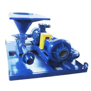
HHF-1300/1600 Mud Pumps are horizontal, triplex single acting reciprocating pumps. It feedshigh-pressure circulated drilling fluid to bottom hole, which flushes the bore-hole bottom andcrushes rocks; furthermore, cools and lubricates drill- bits and carries the cuttings (rock chips) tothe surface.The Pump mainly consists of two components, power and fluid ends. The power end includes theassemblies of frame, pinion shaftcrankshaftcrossheads etc.
assemblies of hydraulic cylindervalves, cylinder liner, piston, suction and discharge manifolds andso on. It is designed and manufactured that all parts and components of the pump conform with therequirements specified by the Specification for Drilling and Well Servicing Equipment (API Spec7K). All easily worn parts at the fluid end such as cylinder liner, piston and valve assemblies etc areuniversal and interchangeable and could be replaced with the same type parts and components inconformity to the above-said API Specification. To avoid air hammer and reduce outlet pressurefluctuationa suction stabilizer and discharge pulsation dampener were respectively installed at thesuction pipes and one side of pump outlet. At the other side of pump outlet, a reset safety valve isinstalled to guarantee that the pump pressure would not excess the rated working pressure. Eachmud pump is equipped with a charging pump to ensure good suction performances for the pumpwhile operating at high strokes.A combination of splash and forced lubrication systems has been used to lubricate all gears,bearings and crossheads in the power end. The cylinder liners and pistons in the fluid end will belubricated, cleaned and cooled by water supplied from a spray pump.For conveniences of daily maintenance, a set of special removers/tools will be delivered togetherwith the pump.Except for differences in the gears and bearings at the power end of the pumps., Frame, fluid endand so on for pump HHF1300 are the same as pump HHF1600. For convenience of usersunderstanding and use, the two pumps are introduced simultaneously in the following texts.
2.2 Performance parametersThe performance parameters for pump HHF1300/1600 are shown in the following table II:Table II Performance parameters for pump HHF1300/1600Diameter of cylinder liner and rated pressureStrokenumbers
The mud pump HHF-1300/1600, manufactured by our company, has been completely assembledand test-operated under full load and then discharged all lube oils from power end before beingdelivered to our customers. The pump must be checked and operated according to the followingmethods and measures before being put into formal services. In order to prevent personal injuryduring the performance of any checking and maintenance processes, it must be shut down and notoperating, all safety and protection facilities installed on the prime mover and drive device shouldbe put in safe positions.
The skid under the HHF-1300/1600 pumps is fit for all types of installations, but it is worth to bementioned that although the frame with box structure at the power end has high resistances tobending, but relatively lower resistances against twist; therefore, the supports under the frame mustbe level and with enough strength to bear the pumps dead load and dynamic forces exerted uponduring operation.3.2
In land installation, it is suggested that a mat base with, at least eight pieces of 31276mm305mmboards be placed under the pump skids along the entire length the positions as shownin the Figure 2. The board under the pump skids must, at least, be 12305mmwider than thewidth of the pump skid runner. More solid foundations are required in case of the installation beinglocated in wet or marshy land.
3.3 Permanent installationsWhile the pump being permanently installed on the structural base or concrete slab on a barge ordrilling platform and the pump skid being fixed by bolts, it is essential that the skid be properlyshimmed to prevent the power frame from possible distortion or twists. The pump skid must besolidly sat down on all shims when all bolts are tightened.In case of barge installation, the pump skid is usually bolted to T-beam, the positions for installingshims are shown in the Figure 2 and 3. Properly shimming should be noted to avoid possible twistor distortion. All shims must exceed the full width of the skid beam flanges and have a minimumlength of 12 (305mm).When integral installations for power unit or electric motor and pump skids are required thepump must be fixed on the skids of the T beam, with retention blocks rather than bolts in thisway the pump could be a bit floating so as to reduce greatly the possible deformation of thepump frame caused by the deformation of barge deck or platform.
Whether to use V- belt or multi-strand chain or universal shaft for the drive between power sourceand the pump, it must be very careful during the whole installation to ensure the longest service lifeand minimize the shut- downs caused by failures from the drive.Upon installation of drive sheave or sprocket, make sure all rust preventatives or greases in the huband on the shaft are removedBurs and rough spots on the keyskeyways and shaft must beremoved so that all keys fit properly in the keyways on the shaft and drive elements. The shaft ofthe pinion gear should be coated with light lube oil or anti-seize oil, and then fit the hub of sheaveor sprocket, tighten all bolts according to the following requirements:Tightening bolts with wrench or wrench with extension pipe may lead to exceeding torque,therefore, it is imperative to adhere to the torque value given in the following table to tighten allbolts, otherwise, it may damage the hub and the sheave by the exceeding tightening force, which isagain multiplied by the wedging action of the tapered surface. In addition, all bolts of hub must betightened alternately and gradually.
3.4.1.1 Checking sheave groove statusBefore installation, check that the sheave grooved are not worn out and getting rounded, otherwise,the V-belt will be damaged quickly. The groove sidewall must be level and straight and there are nodusts, rusts.3.4.1.2 Checking sheave alignmentHaving installed all sheaves and tightened them to working status check their alignment. If thedistances from one side of the two sheaves to the centerline of sheave groove are equal, check thealignment with two tightened strings (for fishing or better for piano) along one side of the twosheaves; one is put above the sheave center and another below the center, and then move one oftwo sheaves until the strings have touched 4 points of the sheave rim; in this way determining thetwo centerlines of the drive sheaves are parallel and their side face be vertical with their axle line.3.4.1.3 adjustment of V-belt pretension forceTo adjust the belt tension, change/increase the central distance between two sheaves until no sag tobe found on the tightening belt side, and the slack side is also tightened but has a bit of sags. Andthen increase a certain of central distance again, for example, if the center distance is 100(2540mm), 1/2 (13mm) is to be increased after completion of adjustment of the central distance;again if the center distance is 150 (3810mm), 3/4 (19mm) is to be increased.Note: Dont obtain belt tension by lifting the pump or by lowing the pump below ground level toallow the belt to be tensioned by pumps weight.3.4.2 Chain drive3.4.2.1 InstallationInstallation and maintenances correctly are important means to extend the service life of chaindrive and chains and sprockets themselves. Many factors such as the width of chain, center distance,speed and load etc. are to be considered when determining the allowable alignment tolerance ofsprockets; since there is no perfect operating method to be applied, therefore, what we can do isto make the chain alignment as exactly as possible. As mentioned above in 3.4.1.2, a more precisealignment can be made with two stretching steel wires (better for piano) along one side of the bothsprockets; one is put above the centerline and another below the centerline, and then move one oftwo sprockets until the strings have touched 4 points of the sprocket rim; in this way, to determine
the two centerlines of sprockets are parallel and their end face be vertical with their axle line.3.4.2.2 Lubrication of chain driveThe lubrication system used for all chain drive in HHF series pumps is an independent one, whichhas its own lube oil pump, reservoir and drive. Filling the lube oil into the chain case must be up tothe indicated height. The lube oil to be used are as follows:Ambient temperature above 32 F 0C
If Ambient temperature below 0F-18C, Please consult a reputable lube oil dealer forrecommendations. As for those approved lube-oil specifications and their supplements, referencesmight be made to the reports/bulletins usually used on lube oil, which are written and published byoil-manufacturer. If there is any discrepancy between manual and the reports/bulletins, thesuggestion from the reports/bulletins shall be prevailed.Owing to the chain lube system being an independent system, the maintenance must be carried outbased on equipments special requirements, which include:n Daily checking oil leveln Daily checking oil statusn Daily checking oil pressure (515psi 0.0350.103MPan Supplying some oils to chainn Checking nozzles working status on the spray tuben Checking the working conditions of the oil pumps drive (V-belts, or chain)Note:a. There is a pressure relief adjusting screw on the rear of the pump housing to adjust the oilpressure.b. When oil pressure is too high or too low, which indicate that the suction and discharge filterscreens need cleaning.
The design of pump suction system has been considered to install the system independently. Toobtain a satisfied suction performance, the HHF series pumps must have positive head (pressure);
the optimum pressure for suction manifold is 2030psi 0.140.21Mpa. Under this pressure,the pump could have the maximum volumetric efficiency and the longest service life forconsumable parts. This pressure can be obtained by 56 charging pump with a 40 hp, 1150-rpmelectric motor. A special kind of device is necessary to keep the charging pump and the triplexpump automatically and synchronously turned on and off. For drilling rigs driven by DC motor,usually a signal sending out from DC control panel actuates the electromagnetic starter; at this time,the air line of drilling pump clutch can provide a group of contactors when clutch is engaged,through which supply power to the electromagnetic starter.The suction pipeline should be arranged with a by pass for the charging pump, to facilitate thedrilling pumps continuous operation when the charging pump is in maintenance or failure. Whenthe drilling pump is operated without charging pump, usually replace a softer suction valve springto improve suction performances.Suction stabilizer is a very efficient supplementary device, which can fully charge the fluid intocylinder liner and greatly eliminate the fluid fluctuations in suction pipes resulting in a smootherflow in the discharge line.Note: Dont connect the discharge pipe of the safety valve to the suction pipeline, since when thesafety valve opens it causes a sudden rise to the system internal pressure; if the pressure is higherthan the rated pressure of the system, it will damage the manifold, suction stabilizer and centrifugalpump etc.
5 Preparation of power endBefore being shipped to the users, the HHF series pump manufactured by our company has beencompletely assembled and test operated. All lube oils have been drained. Before operating thepump, the following operations and checks must be carried out.5.1 Power end lubricationBefore filling lubricant, open inspection window on cover and check power end oil reservoir forpossible accumulation of condensation, and drain and flush the inner chamber by removing thepipe plugs on each side of the pump (see item 2, Fig.7). Fill in the proper brand and quantity oflubrication oil in the power end according to the requirements specified on the designation plate of
pump frame.Recheck oil level after pump has operated for a period of 15 minutes. Shut pump down for about 5minutes until oil stabilized, check oil level gauge (see item 1, Figure 7). It is usually necessary for afew more gallons (10 liters) of oil to be added due to a certain amount being retained in thecrosshead and frame cavities.5.2 Installation and inspection of Crosshead Extension Rods and Diaphragm Stuffing BoxSeals for HHF-1300/1600 PumpAs shown in Figure 4, remove the diaphragm stuffing box and splash- guard (1) and rotatepump so that crosshead is at the front of the stroke, check bolt-tightening status. If the cleanlinessof front part of crosshead and its extension rod and bolt- tightening are not up to the requirements,remove the extension rod and thoroughly clean the crosshead front and the end face of theextension rod; and then insert alignment boss on crosshead extension rod outer circle into thecrosshead bore and install the bolts (2) to the torque: 350370 ft.lbs, (475500N.M), finally lockit with steel wire.
6 Spray pump assemblyThe spray pump assembly consists of spray pump, water tank and spray pipe with nozzles etc. Thefunction of spray pump is to supply water in the form of spray to the cylinder liner and piston toflush, lubricate and cool them to extend the service life of the cylinder liner and piston.
The spray pump is a centrifugal pump, which is electric motor driven and uses water as cooling andlubrication fluid. Attention must be paid to assure the cooling fluid is supplied to the cylinder linerand piston, otherwise immediate damage of piston rubber parts and cylinder liner will occur.The HHF series mud-pumps manufactured by our company use a stationary spray pipe, as shown inFigure 5, which consists of a fixture (1), connecting pipe (2) and spray nozzle pipe (3). It sprays thecooling fluid to inner holes of cylinder liner and piston. The spray nozzle pipe should be checkedoften as the pump works. Through adjustment of water supply to the manifold, to assure enoughcooling fluid to be sprayed directly to piston.
Figure 5Cooling fluid will be transfused by pump (item3, Figure 7), and sucked from water tank (item 5,Fig.7), to the manifold located in the left (right) wall plate of the frame. By regulating the ballvalve (item 4, Fig.7), the pump will supply water to the inside of the cylinder liner withoutsplashing back on the crosshead extension rod. Water should not splash on the extension rodotherwise some of water will spray into the power end contaminati


 8613371530291