
mud pump valve insert free sample
A wide variety of mud pump valve inserts options are available to you, such as 1 year, not available.You can also choose from new, mud pump valve inserts,as well as from energy & mining, construction works , and machinery repair shops mud pump valve inserts, and whether mud pump valve inserts is 1.5 years, 6 months, or 3 months.
A wide variety of mud pump insert valve options are available to you, such as 1 year, not available.You can also choose from new, mud pump insert valve,as well as from energy & mining, construction works , and machinery repair shops mud pump insert valve, and whether mud pump insert valve is 1.5 years, 6 months, or 3 months.

Mud Pump Valve & Seat are made of premium alloy steel through one-piece forging and carburizing treatment processes, thereby ensuring high intensity. In addition, the precise calculation is performed and CNC machining is conducted for the dimensional matching of the valve seat and valve body working angles to enhance the service life of the valve body and valve seat. Our valve products are able to work smoothly in normal mining and digging conditions for over 400 hours.

The 2,200-hp mud pump for offshore applications is a single-acting reciprocating triplex mud pump designed for high fluid flow rates, even at low operating speeds, and with a long stroke design. These features reduce the number of load reversals in critical components and increase the life of fluid end parts.
The pump’s critical components are strategically placed to make maintenance and inspection far easier and safer. The two-piece, quick-release piston rod lets you remove the piston without disturbing the liner, minimizing downtime when you’re replacing fluid parts.
The present invention relates generally to valves used in pumps handling abrasive fluids. More specifically, the present invention provides an improved valve seat which significantly reduces the impact stress on valves and seat assemblies during the pumping operation, resulting in reduced wear on the valve assembly and improved reliability for the pumping system.
Pumping systems which are used to pump drilling mud and other abrasive fluids generally incorporate positive displacement pistons or plungers which operate in a reciprocating manner in individual cylinders. Each piston or plunger cylinder has a suction and discharge valve and valve seat operating alternatingly and independently to control flow into and out of each cylinder. The valve typically comprises a disc-shaped body portion which includes an elastomeric valve insert which serves to seal the valve when in the closed position and also serves to cushion the impact of the valve body in the valve seat. A lower conical seating surface of the valve body also makes contact with the valve seat when the valve is in the closed position.
Because of high pump pressures (between 2000 and 5000 psi) and the abrasive solid particles suspended in the drilling mud, valves and valve seats wear at a rapid rate and must be replaced frequently. One of the most significant points of impact stress in the valve assembly is the point of contact of the lower conical portion of the valve body and the valve seat when the valve is in the closed position. The extremely high differential pressures in the valve cause the conical portion of the valve body to engage the valve seat with a very high impact. The repetitive impact eventually causes the faces of the valve body and the valve seat to become worn and pitted. There is a need for an improved valve seat which reduces the impact stress related to the impact of the valve body with the valve seat.
The apparatus of the present invention overcomes the difficulties of the prior art by providing an improved valve seat which significantly decreases the impact stress caused by the impact of a mud pump valve body against the valve seat. The valve seat comprises a generally cylindrical body portion with a sealing surface which is sloped from the outer surface of the cylindrical body portion toward an interior throat of said cylindrical body portion. The valve body comprises a generally disc-shaped portion and a truncated contical portion. An elastomer insert is received in a groove in the valve body. The conical portion of the valve comprises a sloped face, including a metal portion and an elastomeric portion formed by the elastomeric insert. In the valve seat of the present invention, an annular pressure relief groove in the cylindrical body portion of the valve seat allows the sloped face of the valve seat to flex thereby relieving a significant amount of the impact load between the opposing faces of the valve assembly.
FIG. 2a is a cross-sectional view of the valve assembly of FIG. 1, showing the valve received in the valve seat with the valve in the closed position, just prior to maximum impact of the valve body against the valve seat.
FIG. 2b is cross-sectional view of the valve assembly of FIG. 1, showing the valve received in the valve seat with the valve in the closed position just after maximum impact of the valve body against the valve seat.
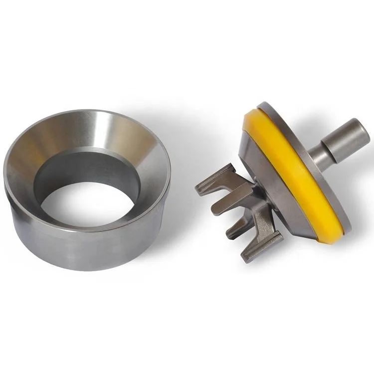
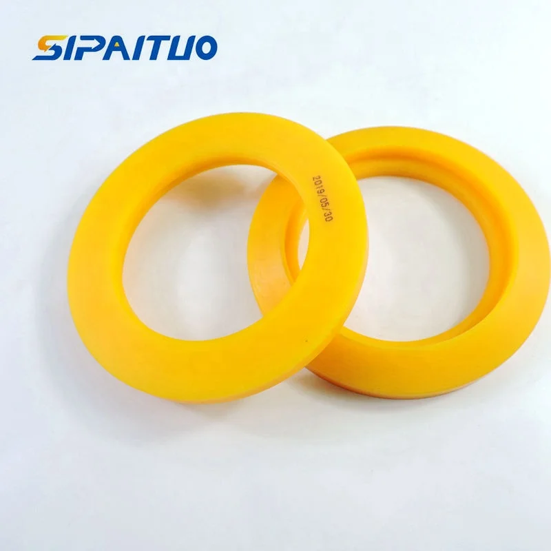
FIG. 1 is a perspective view of a mud pump valve assembly 10 comprising the improved valve seat of the present invention. The valve assembly shown in FIG. 1 is in the full open position. The valve assembly 10 is broadly comprised of a valve body 12 and a valve seat 14. The valve body comprises an upper valve guide 16 which maintains proper registration of the valve body within the pump housing. A plurality of valve guide feet 18 serve to maintain proper alignment of the valve with respect to the valve seat 14. The valve body comprises a generally disc-shaped portion 20 which is formed of metal, such as steel which has been heat treated by a carburizing process. The outer portion of the disc-shaped body has a generally C-shaped cross-section with an annular groove being defined by the interior of the C-shaped portion. A polyurethane or rubber insert is received in this groove. The insert serves to provide a partial damping of the impact of the valve body against the valve seat. However, this impact in most prior art systems is still high enough to cause significant wear on the operating faces of the valve body and the valve seat.
The lower portion of the valve body has a somewhat conical cross-section with a sloped surface illustrated by reference numeral 24. The sloped surface 24 comprises a rubber portion illustrated by reference numeral 26 and a metal portion illustrated by reference numeral 28. The valve seat 14 comprises a seating surface 30 with a portion 32 which engages the rubber portion 26 of the valve body surface and a portion 34 which engages the metal portion 28 of the valve body surface. FIG. 2a is a cross-sectional view of the valve assembly of FIG. 1, showing the valve received in the valve seat with the valve in the closed position, just prior to maximum impact of the valve body against the valve seat. FIG. 2b shows the valve received in the valve seat with the valve in the full closed position, with maximum impact of the valve body against the valve seat. Typically, the elastomer portion of the valve seating surface will make initial contact with the seating face of the valve seat. This is illustrated in FIG. 2a by the contact of the sloped face 26 of the elastomer insert 22 against the portion 32 of the sloped metal face of the valve seat. Note that the metal portion 28 of the sloped face of the valve body is not yet in contact with the portion 34 of the sloped face of the valve seat. The extremely high differential pressure on opposite sides of the valve, however, causes the elastomer insert 22 to compress rapidly to the position illustrated by the compressed elastomer insert 22 shown in FIG. 2b. The rapid compression of the elastomer insert results in an extremely high impact of the metal portion 28 of the valve face with the portion 34 of the valve seat face. In prior art valve seats this results in rapid wear of the metal portion 28 of the valve body and the portion 34 of the valve seat face. In the valve seat of the present invention, however, an annular pressure relief groove 36 allows the sloped face of the valve seat to flex thereby relieving a significant amount of the impact load between the opposing faces of the valve assembly.
Details relating to the valve seat 14 can be seen by referring to the cross-sectional illustration of FIG. 3. The outer surface of the valve seat comprises a valve seat shoulder 38 and a sidewall 40 having a conical taper. The slope of the sidewall 40 allows the valve seat to be received in a standard pump deck portion of a valve pot. The valve seat throat 42, defined by the internal cylindrical sidewall 44, transports the fluid passed through the valve assembly.
FIG. 4 is an enlarged view of a portion of the valve seat of the present invention showing details relating to the annular pressure relief groove 36. The relief groove is defined by vertical sidewalls 46 and 48 and an arch connecting the upper portions of the sidewalls 46 and 48. The arch is defined by two 90 degree segments with the inside segment having a radius which is two times as large as the radius of the outside 90 degree segment. The tangent point, illustrated by the reference numeral 50 is a point of smooth transition between the radii of the inside and the outside radii of the arch. The inside portion of the arch having the increased radius corresponds to the portion of the valve seat face which bears the impact of the metal portion of the valve body. Thus the impact load transmitted from the seating surface is dispersed over the larger radius inside the relief groove. This configuration maximizes flexure of the seating surface while preventing a stress concentration that would result in catastrophic shear failure of the seat.
Wear in the seating surface is directly proportional to the impact stress on the seating surface area of the valve seat. Impact stress "σ," which is reduced by the increased flexibility of the design of the present invention, is calculated using the following formula:
Utilizing finite element stress analysis, the calculated values for σs are approximately equal for the seating surface of a seat designed by the prior art and for the seating surface of the present invention. For both designs, the value of "h" is fixed and equal, being determined by the valve body and insert design. Again by finite element calculations, "y," deflection, is increased by a factor of 2 for the present invention. Using these values, the above equation yields values for impact stress, "σ," that are reduced by approximately 30% by the present invention.
The elastomeric insert is also positively affected by the present invention. The elastomeric seal, which is usually made of rubber or polyurethane material does not wear in the manner that the metal valve body and valve seat wear, i.e., through material loss. Material loss of the elastomeric seal is small during normal pump operation. Instead, the constant cyclical compression of the seal results in hysterisis in the seal that results in internal heat buildup and the eventual degradation of material strength to the point that the seal fails. As the metal valve and seat wear in the form of material loss from the impact stress, the amount of compression increases, hysterisis also increases to the point that material strength loss in the seal is accelerated and seal failure occurs after a shorter number of total cycles. Therefore, reduction in the wear rates of the metal valve body and valve seat also increases the life of the valve seal.
The flexible seat design of the present invention also improves pump operation because the valve opens faster and allows the pumped fluid to enter or leave the cylinder quicker. Because of the increased seat deflection, the seat stores energy that can be used to accelerate the valve to the open position before the piston or plunger begins the next stroke. In other words, the increased seat deflection acts like a recoiled spring which results in faster valve opening for smoother and more efficient pump operation.

Present embodiments relate generally to the field of drilling and processing of wells, and, more particularly, to a mud saver valve for controlling flow of mud or other fluid during insertion of casing elements into a wellbore during drilling and completion operations and the like.
During drilling or completion of the well, the drilling rig may be used to insert joints or stands (e.g., multiple coupled joints) of tubular into the wellbore. As an example, during insertion of tubular into the wellbore by a traditional operation, each tubular element (e.g., each joint or stand) is coupled to an attachment feature, such as an elevator, that is in turn lifted by a traveling block of the drilling rig such that the tubular element is positioned over the wellbore. An initial tubular element may be positioned in the wellbore and held in place by gripping devices, such as slips or a spider, near the rig floor. Subsequent tubular elements may then be aligned with and coupled to the existing tubular elements in the wellbore to continue formation of the tubular string (e.g., casing string or drill string).
During insertion of tubular elements (e.g., casing) into a wellbore during completion operations, a flow of mud or other fluid may be pumped into the tubular elements and wellbore to facilitate the tubular or casing running operation. It is now recognized that certain aspects of these existing techniques are not optimal because of various limitations (e.g., equipment limitations) during certain phases of operation. For example, when a flow of mud or other fluid is circulated, mud or other fluid can inadvertently be spilled onto a rig floor during certain phases of operation. Existing valves to control the flow of mud during insertion and/or removal of tubular elements may be costly, susceptible to wear and corrosion, and so forth.
In accordance with one aspect of the disclosure, a system includes a mud saver valve assembly having a first sleeve, a second sleeve, and a first valve element axially captured between the first sleeve and the second sleeve, wherein the first valve element includes a support ring portion extending about a circumference of the first valve element and a center portion extending across the support ring portion, wherein the center portion comprises a dome-shaped geometry.
In accordance with another embodiment of the disclosure, a system includes a casing running tool configured to couple to a casing element and add the casing element from a casing string and a mud saver valve assembly disposed within the casing running tool, wherein the mud saver valve assembly is configured to flow a fluid through the casing running tool and into the casing element, the mud saver valve assembly includes a valve element extending across a flow path of the mud saver valve assembly, and the valve element is formed from an elastomer.
In accordance with a further aspect of the disclosure, a system includes an upper annular sleeve comprising a first axial recess, a lower annular sleeve comprising a second axial recess, a valve element axially captured between the upper annular sleeve and the lower annular sleeve, wherein the valve element includes a support ring extending about a circumference of the valve element, wherein the support ring has a first axial contour and a second axial contour and a dome-shaped center portion extending between the support ring, wherein the first axial contour is disposed within the first axial recess, the second axial contour is disposed within the second axial recess, and the valve element is formed from a rubber.
FIG. 3 is a partial cross-sectional side view of an embodiment of the mud saver valve assembly, illustrating a valve element captured between sleeves of the mud saver valve assembly;
FIG. 6 is a cross-sectional side view of a valve element of the mud saver valve assembly in an opened position, in accordance with present techniques; and
Present embodiments are directed to systems and methods for controlling circulation of mud or other fluid within a wellbore during insertion of tubular elements (e.g., casing) into a wellbore during wellbore completion operations and the like. A casing running tool (e.g., tubular running tool) may be used to facilitate assembly and disassembly of casing strings. Indeed, a casing running tool may be employed to engage and lift a tubular element (e.g., a casing joint or element), align the tubular element with a casing string, stab a pin end of the tubular element into a box end of the tubular string, engage the casing string, and apply torque to make-up a coupling between the tubular element and the casing string. Thus, a casing running tool may be employed to extend the tubular or casing string. Similarly, the casing running tool may be used to disassemble tubular or casing elements from a casing string by applying reverse torque and lifting the tubular elements out of the engagement with the remaining casing string. It should be noted that torque may be applied using a top drive system coupled to the casing running tool or integral with the casing running tool.
During a process of installing or removing tubular or casing elements, it may be desirable to circulate fluids (e.g., drilling mud) through the associated casing string. Accordingly, the casing running tool may be configured to create a flow path between the tubular handling equipment and the tubular or casing element such that fluid can efficiently pass from the casing running tool into the tubular element, and thereafter the casing string. In accordance with present embodiments, a flow of mud or other fluid through the tubular elements and within the wellbore may be regulated during insertion of the tubular or casing elements. For example, the flow of mud or other fluid may be automatically enabled when a casing running tool is coupled to a tubular element and/or when a mud pump for pumping drilling mud is in a pumping mode. The flow of mud or other fluid may be blocked when the casing running tool is decoupled from a tubular element or casing string and/or when the mud pump is not in a pumping mode. To this end, present embodiments include a mud saver valve assembly that may be disposed within or coupled to the casing running tool. The mud saver valve assembly includes a valve element configured to block mud or fluid flow when a fluid flow pressure applied to the valve element is below a threshold pressure, while enabling mud or fluid flow when the fluid flow pressure applied to the valve element is above the threshold pressure. For example, the threshold pressure may be equal to or greater than a head pressure of mud or fluid that may be contained in the casing running tool and/or a mud hose when the mud pump is not in a pumping mode. Thus, when the mud pump is not pumping mud or other fluid (e.g., when the casing running tool is not coupled to a tubular element to be added to a casing string), the valve element may block flow of mud or fluid still contained in the casing running tool or mud hose, thereby preventing inadvertent flow of mud from the casing running tool and onto a rig floor or platform. However, when the pressure applied to the valve element is greater than the threshold pressure (e.g., when the mud pump is in a pumping mode as the pipe drive system is coupling a tubular element to the casing string), the valve element enables flow of mud through the casing running tool and into the tubular element and casing string.
The length of casing 38 is held in place by a casing running tool 40 that is hanging from the traveling block 22. Specifically, a gripping device 42 of the casing running tool 40 is engaged about an outer perimeter of a distal end 44 of the casing 38. This attachment via the gripping device 42 enables the casing running tool 40 to maneuver the casing 38. In the illustrated embodiment, the casing running tool 40 is holding the casing 38 in alignment with the stump 36. The gripping device 42 may include an integral seal or may be configured to couple with the casing 38 about a seal such that a sealed passage is established between the casing running tool 40 and the casing 38. Establishing this sealed passage facilitates circulation of fluid (e.g., drilling mud) through the casing running tool 40 into the casing 38 and the casing string 28. Further, the gripping device 42 couples with the casing 38 in a manner that enables translation of motion to the casing 38. Indeed, in the illustrated embodiment, the casing running tool 40 includes a top drive 46 configured to supply torque for making-up and unmaking a coupling between the casing 38 and the stump 36. It should be noted that, in some embodiments, the top drive 46 is separate from the casing running tool 40.
To facilitate the circulation of mud or other drilling fluid within the wellbore 30, the drilling rig 10 includes a mud pump 48 configured to pump mud or drilling fluid up to the casing running tool 40 through a mud hose 50. In certain embodiments, the mud hose 50 may include a stand pipe 52 coupled to the derrick 14 in a substantially vertical orientation to facilitate pumping of mud. The stand pipe 52 provides a high-pressure path for mud to flow up the derrick 14 to the casing running tool 40. From the mud hose 50 (e.g., stand pipe 52), the mud flows through a kelly hose 53 to the casing running tool 40. From the casing running tool 40, the drilling mud will flow through internal passages of the gripping device 42, into internal passages of the casing 38 and the casing string 28, and into the wellbore 30 to the bottom of the well. The drilling mud flows within the wellbore 30 (e.g., in an annulus between the casing string 28 and the wellbore 30) and back to the surface where the drilling mud may be recycled (e.g., filtered, cleaned, and pumped back up to the casing running tool 40 by the mud pump 48).
The illustrated embodiment of the drilling rig 10 further includes a controller 54 having one or more microprocessors 56 and a memory 58. The memory 58 is a non-transitory (not merely a signal), computer-readable media, which may include executable instructions that may be executed by the microprocessor 56. The controller 54 is configured to regulate operation of the mud pump 48 and/or other features of the drilling rig 10. For example, the controller 54 may be configured to regulate a flow rate of mud or other drilling fluid circulated through the casing string 28 and the wellbore 30 during installation of tubular elements (e.g., casing 38). For example, the controller 52 may regulate operation of the mud pump 48 to start, stop, increase, and/or decrease mud flow into the casing string 28 and wellbore 30 during installation of casing 38 elements. The controller 52 may also regulate other components of the drilling rig 10 to control flow of drilling mud. For example, the controller 52 may control operation of the casing running tool 40 and/or a valve disposed along the mud hose 50.
As discussed in detail below, the casing running tool 40 also includes a mud saver valve assembly 60. When a new length of casing 38 is to be added to the casing string 28, mud flow from the pump 48 and the mud hose 50 is stopped, and the casing running tool 40 (e.g., the gripping device 42) is removed from the casing string 28 (i.e., the length of casing 38 most recently added to the casing string 28). When the casing running tool 40 releases the casing string 28, mud within the casing running tool 40 may run out of the casing running tool 40 and onto the rig floor 12. To avoid spilling mud onto the rig floor 12, the casing running tool 40 includes the mud saver valve assembly 60 to block flow of mud from out of the casing running tool 40 when the mud pump 48 is not pumping mud. When the casing running tool 40 is thereafter coupled to a new length of casing 38 and the mud pump 48 resumes a pumping operation, the mud saver valve assembly 60 automatically enables flow of mud through the mud saver valve assembly 60 and the casing running tool 40 to the casing 38 and casing string 28.
As described below, the mud saver valve assembly 60 includes a valve element configured to block mud flow through the mud saver valve assembly 60 when the mud pump 48 is not running (e.g., pumping) and/or when the casing running tool 40 is decoupled from the casing 38 and/or casing string 28. In this manner, the mud saver valve assembly 60 may block mud remaining in the casing running tool 40, kelly hose 53, and/or mud hose 50 (e.g., stand pipe 52) from inadvertently flowing out of the casing running tool 40 and onto the rig floor 12 when the casing running tool 40 is decoupled from the casing 38. When the mud pump 48 is running and pumping a mud flow (e.g., when the casing running tool 40 is coupled to casing 38), the valve element may automatically enable flow of mud through the casing running tool 40 and into the casing 38. For example, the valve element may have a material construction, geometry, and/or shape that enables blockage of mud flow when the mud pump 48 not pumping, while enabling automatic flow of the mud when the mud pump 48 is pumping. As discussed further below, the valve element of the mud saver valve assembly 60 may also be formed from a durable, resilient, corrosion resistant material, thereby enabling improved longevity and useful life of the valve element and the mud saver valve assembly 60.
FIG. 2 is a cross-sectional side view an embodiment of the mud saver valve assembly 60, illustrating a valve element 80 captured between sleeves 82 of the mud saver valve assembly 60. More specifically, the valve element 80 is axially captured between an upper sleeve 84 and a lower sleeve 86. For example, the upper and lower sleeves 84 and 86 may be tubes or annular members, and the valve element 80 may have a generally circular outer diameter. In other embodiments, the upper and lower sleeves 84 and 86 and the valve element 80 may have other geometries (e.g., square, rectangular, polygonal, elliptical, etc.). As mentioned above, the mud saver valve assembly 60 is coupled to (e.g., positioned within) the casing running tool 40. For example, the mud saver valve assembly 60 may be threaded, bolted, clamped, or otherwise mechanically attached to the casing running tool 40. The upper and lower sleeves 84 and 86 generally define a flow path 85 through which a flow of drilling mud or other fluid may flow through the casing running tool 40 and into the casing element 38. When the casing running tool 40 is coupled to a length of casing 38, the mud saver valve assembly 60 is inserted axially into (e.g., “stabbed” into) the casing 38. In this manner, drilling mud may flow from the casing running tool 40, through the mud saver valve assembly 60, as indicated by arrow 88, and into the casing 38 when the mud pump 48 is pumping. As will be appreciated, the mud saver valve assembly 60 and/or the casing running tool 40 may include seals 89 (e.g., O-rings, axial seals, annular seals, etc.), gaskets, and/or other components configured to enable a flow of mud or other fluid through the casing running tool 40, the mud saver valve assembly 60, and the casing 38.
As mentioned above, the valve element 80 is configured to block mud flow through the mud saver valve assembly 60 and, thus, the casing running tool 40 when the mud pump 48 is not pumping, while automatically enabling mud flow through the mud saver valve assembly 60 and, thus, the casing running tool 40 when the mud pump 48 is pumping. To this end, the valve element 80 is formed from a flexible, yet resilient, material. For example, the valve element 80 may be formed from a rubber (e.g., steel-belted rubber), polyurethane, neoprene, other elastomer, or other suitable material. In certain embodiments, the valve element 80 may be a single molded piece. Additionally, to enable blockage of flow and/or retention of mud within the casing running tool 40 when the mud pump 48 is not in a pumping mode, the valve element 80 has a dome-shaped geometry or shape. Details and functionalities of the dome-shaped geometry of the valve element 80 are discussed in further detail below with reference to FIGS. 4-6. The sleeves 82 of the mud saver valve assembly 60 may be formed from any suitable and durable (e.g., corrosion and/or wear resistant) material, such as steel, plastic, or other material.
FIG. 3 is a partial cross-sectional side schematic view, taken within line 3-3 of FIG. 2, of the mud saver valve assembly 60, illustrating axial capture of the valve element 80 between the sleeves 82. The upper and lower sleeves 84 and 86 are coupled to one another, as indicated by arrow 100, with the valve element 80 at least partially between the upper and lower sleeves 84 and 86. In certain embodiments, the upper and lower sleeves 84 and 86 may be coupled to one another via a threaded connection, a shrink fit, an interference fit, bolts, clamps, or other fasteners. In the illustrated embodiment, the upper sleeve 84 is disposed about the lower sleeve 86, but in other embodiments the lower sleeve 86 may be disposed about the upper sleeve 84. In yet another embodiment, the upper and lower sleeves 84 and 86 may at least partially axially abut one another. Furthermore, the upper and lower sleeves 84 and 86 may include seals, gaskets, or other components disposed therebetween to block leakage of drilling mud or fluid from the mud saver valve assembly 60.
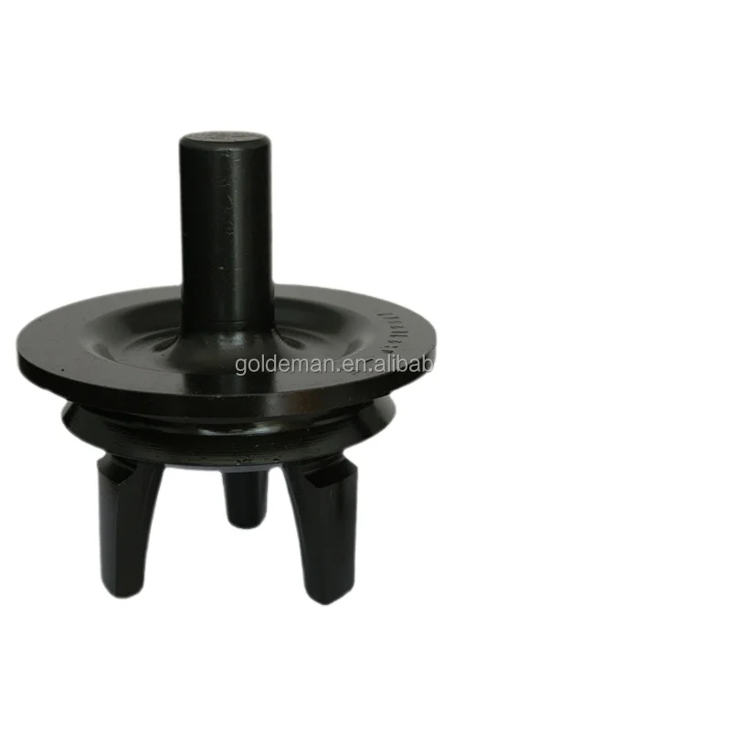
As discussed below, the valve element 80 includes a support ring portion 102 (e.g., radially outer ring) and a center portion 104 (e.g., dome-shaped portion). The support ring portion 102 is axially captured and retained between the upper and lower sleeves 84 and 86. To facilitate the axial capture of the valve element 80, the support ring portion 102 has an upper axial contour 106 and a lower axial contour 108. The upper axial contour 106 of the support ring portion 102 is received (e.g., nested within) a corresponding axial recess 110 of the upper sleeve 84 having a similar contour. Likewise, the lower axial contour 108 of the support ring portion 102 is received (e.g., nested within) a corresponding axial recess 112 of the lower sleeve 86 having a similar contour. When the upper and lower sleeves 84 and 86 are coupled to one another, the upper axial contour 106 and the lower axial contour 108 of the support ring portion 102 are captured by the axial recess 110 and the axial recess 112, respectively, thereby securing the support ring portion 102 and, thus, the valve element 80 between the upper and lower sleeves 84 and 86. When the valve element 80 is axially captured by the upper and lower sleeves 84 and 86, the center portion 104 extends across the flow path 85 of the mud saver valve assembly 60.
FIG. 4 is a perspective view of the valve element 80, illustrating the support ring portion 102 and the center portion 104. As described above, the support ring portion 102 is axially captured between the upper and lower sleeves 84 and 86 to secure the valve element 80 within the mud saver valve assembly 60. The center portion 104, which extends between the circular support ring portion 102, is exposed to an interior (e.g., flow path 85) of the mud saver valve assembly 60. Thus, the center portion 104 is exposed to a mud flow within the casing running tool 40.
As mentioned above, in one embodiment, the valve element 80 is formed from a flexible, yet resilient, material, and the center portion 104 has a dome-shaped configuration. The center portion 104 is further divided into sections or segments 120. More specifically, the center portion 104 is cut or sliced to divide the center portion 104 into the segments 120. For example, in the illustrated embodiment, the center portion 104 has two slits 122 extending across a diameter or width of the center portion 104 at approximately 90 degrees relative to one another. As a result, the center portion 104 is divided into four segments 120. Other embodiments of the valve element 80 may include other numbers of slits 122 (e.g., diameter slits and/or radial slits) to divide the center portion 104 into other numbers of segments 120 (e.g., 3, 5, 6, 7, or more segments 120). As will be appreciated, the individual segments 120 may move (e.g., bend) independently from one another.
FIG. 5 is a cross-sectional side view of the valve element 80, illustrating the dome-shaped configuration of the center portion 104. While the flexible, resilient material of the valve element 80 enables deformation (e.g., bending) of the segments 120 of the center portion 104, the dome-shaped configuration of the center portion 104 enables the valve element 80 to withstand a threshold pressure (e.g., stagnant drilling mud in the casing running tool 40 when the mud pump 48 is not pumping mud) without deformation of the segments 120. The number of segments 120, the type of material, the length of the slits 122, the size of the valve element 80, and so forth, may be calibrated based on empirical data to fully/partially open at certain pressures.
A concave side 140 of the center portion 104, which is exposed to the drilling mud flow from the casing running tool 40 (e.g., an upstream direction of the drilling mud flow), may withstand a threshold pressure (e.g., amount of drilling mud) applied to the concave side 140 of the center portion 104 without deforming to the point that the pressure (e.g., drilling mud) traverses or flows past the center portion 104. As will be appreciated, the threshold pressure of the concave side 140 of the center portion 104 may generally correspond to a pressure head of drilling mud that may be within the casing running tool 40, kelly hose 53, and/or stand pipe 52 when the casing running tool 40 is decoupled from the casing string 28 and the mud pump 48 pumping operation is suspended. The particular threshold pressure that the concave side 140 of the center portion 104 can withstand without allowing the pressure to traverse the center portion 104 (e.g., via excessive bending of the segments 120) may be selected by adjusting various design parameters of the center portion 104 and/or the valve element 80. For example, a material of a particular resilience may be selected to manufacture the valve element 80, such that the segments 120 do not deform and open the valve element 80 until a particular pressure applied to the concave side 140 is reached. Additionally, a number of segments 120, a thickness 142, and/or a radius of curvature 144 of the center portion 104 may be selected to achieve a desired pressure withstanding capability of the concave side 140 of the valve element 80. In certain embodiments, parameters of the valve element 80 (e.g., material resilience, number of segments 120, thickness 142, and/or radius of curvature 144) may be selected to achieve a threshold pressure of 50, 60 70, 80, 90, 100, 110, 120 pounds per square inch, or more.
Moreover, pressure (e.g., drilling mud) below the threshold pressure that is applied to the concave side 140 of the center portion 104 may improve a seal created by the center portion 104 when the mud pump 48 is not pumping mud to the casing running tool 40. For example, as indicated by arrows 146, pressure applied to the concave side 140 of the center portion 104 may cause the segments 120 of the center portion 104 to press against one another due to the dome-shaped configuration of the center portion 104. That is, a seal interface 148 (e.g., at slits 122) between adjacent segments 120 may be strengthened, as indicated by arrows 150, as a pressure below the threshold pressure is applied to the concave side 140. In this manner, the sealing capability of the valve element 80 when the mud pump 48 is not pumping mud to the casing running tool 40 may be improved, thereby further reducing inadvertent leaking of mud or fluid out of the casing running tool 40 (e.g., and onto the rig floor 12) when the casing running tool 40 is decoupled from the casing 38 or casing string 28.
As the valve element 80 and mud saver valve assembly 60 are oriented such that the concave side 140 of the center portion 140 is exposed to the flow of drilling mud within the casing running tool 40, the convex side 152 of the center portion 104 is exposed to the interior of the casing 38 and/or casing string 28 when the casing running tool 40 is coupled to the casing 38 and/or casing string 28. In other words, the convex side 152 is exposed to a downstream side of the mud saver valve assembly 60 relative to a drilling mud or fluid flow. As will be appreciated, the segments 120 will more readily and easily deform (e.g., bend) upon application of a pressure to the center portion 104 from the convex side 152. This may provide additional benefits. For example, the ability of the segments 120 to more easily deform when a pressure 154 (e.g., backpressure within the casing string 28) is applied to the convex side 152 of the valve element 80 may facilitate pressure equalization across the valve element 80.
FIG. 6 is a cross-sectional side view of the valve element 80, illustrating deformation of the segments 120 of the center portion 104 of the valve element 80 when a pressure greater than the threshold pressure is applied to the concave side 140 of the center portion 104. As discussed above, the threshold pressure that the concave side 140 of the center portion 104 may withstand and remain sealed may correspond to a pressure head of drilling mud that may be within the casing running tool 40, kelly hose 53, and/or stand pipe 52 when the casing running tool 40 is decoupled from the casing string 28 and the mud pump 48 pumping operation is suspended. However, when the mud pump 48 pumping operation resumes (e.g., when the casing running tool 40 is coupling another length of casing 38 to the casing string 28), the pressure of the drilling mud on the concave side 140 may exceed the threshold pressure, thereby causing the segments 120 to bend (e.g., invert) and, thus, open the valve element 80 to allow flow of drilling mud from the casing running tool 40 and into the casing 38 and casing string 28. After the casing 38 is added to the casing string 28 and another length of casing 38 is to be added, the mud pump 48 pumping operation may be suspended, thereby dropping the pressure applied to the concave side 140 of the center portion 104, and the segments 120 may revert back to their natural or normal shape, as shown in FIG. 5, to close the valve element 80. In this manner, inadvertent flow of drilling mud from the casing running tool 40 (e.g., onto the rig floor 12) may be blocked when the casing running tool 40 is not coupled to casing 38 to be added to the casing string 28.
In certain embodiments, the mud saver valve assembly 60 may include more than one valve element 80. For example, FIG. 7 is a schematic side view of an embodiment of the mud saver valve assembly 60 having two valve elements 80 (e.g., a first valve element 180 and a second valve element 182) disposed in series with one another. Other embodiments of the mud saver valve assembly 60 may have other numbers (e.g., 3, 4, 5, or more) of valve elements 80. Additionally, the respective orientations of the valve elements 80 may vary. For example, one embodiment having two valve elements 80, the concave side 140 of one valve element 80 may face an upstream direction, and the concave side 140 of a second valve element 80 may face a downstream direction. For example, the concave side 140 of the first valve element 180 may face an upstream direction, and the concave side 140 of the second valve element 182 may face a downstream direction, or vice versa.
The illustrated mud saver valve assembly 60 includes the upper and lower sleeves 84 and 86 and also an intermediate sleeve 184. The first valve element 180 is axially captured by the upper sleeve 84 and the intermediate sleeve 184, and the second valve element 182 is axially captured by the intermediate sleeve 184 and the lower sleeve 86. As will be appreciated, the first and second valve elements 180 and 182 may have similar features as the valve element 80 described above. In certain embodiments, the first and second valve elements 180 and 182 may be designed to have the same threshold pressure, while in other embodiments the first and second valve elements 180 and 182 may be designed to have different threshold pressures. For example, in one embodiment, the first valve element 180 may have a first threshold pressure, and the second valve element 182 may have a second threshold pressure that is lower than the first threshold pressure of the first valve element 180. Additionally, the upper sleeve 84, lower sleeve 86, and intermediate sleeve 184 may have similar features as the upper and lower sleeves 84 and 86 described above.
As discussed in detail above, present embodiments include the mud saver valve assembly 60, which may be used with the casing running tool 40 or other component of the drilling rig 10. The mud saver valve assembly 60 is configured to automatically enable the flow of mud or other fluid through the casing running tool 40 when the casing running tool 40 is coupled to the casing element 38 and/or when the mud pump 48 is in a pumping mode (e.g., during a casing running operation). The mud saver valve assembly 60 is further configured to block the flow of mud or other fluid through the casing running tool 40 when the casing running tool 40 is decoupled from the casing element 38 or the casing string 28 and/or when the mud pump 48 is not in a pumping mode. The mud saver valve assembly 60 includes the valve element 80, which is configured to block mud or fluid flow when a pressure applied to the valve element 80 is below a threshold pressure, while automatically enabling mud or fluid flow when the pressure applied to the valve element 80 is above the threshold pressure. For example, the threshold pressure may be equal to or greater than a head pressure of mud or fluid that may be contained in the casing running tool tem 40 and/or a mud hose 50 when the mud pump 48 is not in a pumping mode. Thus, when the mud pump 48 is not pumping mud or other fluid (e.g., when the casing running tool 40 is not coupled to the casing element 38 to be added to the casing string 28), the valve element 80 may block flow of mud or fluid still contained in the casing running tool 40 and/or mud hose 50, thereby blocking inadvertent flow of mud from the casing running tool 40 and onto the rig floor 12. However, when the pressure applied to the valve element 80 is greater than the threshold pressure (e.g., when the mud pump 48 is in a pumping mode as the casing running tool 40 is coupling the casing element 38 to the casing string 28), the valve element 80 automatically enables flow of mud through the casing running tool 40 via deformation (e.g., bending or inverting) of the segments 120 of the valve element 80.
Embodiments of the valve element 80 described above provide additional improvements over exiting mud saver valves. For example, the valve element 80 may be formed from a durable, corrosion resistant, resilient, and wear resistant material, such as rubber, neoprene, or other elastomer. Thus, the valve element 80 may be less costly to produce, while also providing increased useful life. Moreover, the dome-shaped configuration of the valve element 80 enables the valve element to withstand a threshold pressure (e.g., head pressure of mud within the pipe drive system 40 and/or mud hose 50) in a first direction (e.g., direction of mud flow), while also enabling the valve element 80 to equalize pressure across the mud saver valve assembly 60 in a second direction (e.g., to accommodate backpressure within the casing string 28).

Full-Open Valves . . . . . . . . . . . . . . . . . . . . . . . . . . . . . . . . . . . . . . . . . . . . . . . . . . . . . . . . . . . . . . . . . . . . . . 3
Mud-Pump Gear Sets . . . . . . . . . . . . . . . . . . . . . . . . . . . . . . . . . . . . . . . . . . . . . . . . . . . . . . . . . . . . . . . . . 13

If you run a mud rig, you have probably figured out that the mud pump is the heart of the rig. Without it, drilling stops. Keeping your pump in good shape is key to productivity. There are some tricks I have learned over the years to keeping a pump running well.
First, you need a baseline to know how well your pump is doing. When it’s freshly rebuilt, it will be at the top efficiency. An easy way to establish this efficiency is to pump through an orifice at a known rate with a known fluid. When I rig up, I hook my water truck to my pump and pump through my mixing hopper at idle. My hopper has a ½-inch nozzle in it, so at idle I see about 80 psi on the pump when it’s fresh. Since I’m pumping clear water at a known rate, I do this on every job.
As time goes on and I drill more hole, and the pump wears, I start seeing a decrease in my initial pressure — 75, then 70, then 65, etc. This tells me I better order parts. Funny thing is, I don’t usually notice it when drilling. After all, I am running it a lot faster, and it’s hard to tell the difference in a few gallons a minute until it really goes south. This method has saved me quite a bit on parts over the years. When the swabs wear they start to leak. This bypass pushes mud around the swab, against the liners, greatly accelerating wear. By changing the swab at the first sign of bypass, I am able to get at least three sets of swabs before I have to change liners. This saves money.
Before I figured this out, I would sometimes have to run swabs to complete failure. (I was just a hand then, so it wasn’t my rig.) When I tore the pump down to put in swabs, lo-and-behold, the liners were cut so badly that they had to be changed too. That is false economy. Clean mud helps too. A desander will pay for itself in pump parts quicker than you think, and make a better hole to boot. Pump rods and packing last longer if they are washed and lubricated. In the oilfield, we use a petroleum-based lube, but that it not a good idea in the water well business. I generally use water and dish soap. Sometimes it tends to foam too much, so I add a few tablets of an over the counter, anti-gas product, like Di-Gel or Gas-Ex, to cut the foaming.
Maintenance on the gear end of your pump is important, too. Maintenance is WAY cheaper than repair. The first, and most important, thing is clean oil. On a duplex pump, there is a packing gland called an oil-stop on the gear end of the rod. This is often overlooked because the pump pumps just as well with a bad oil-stop. But as soon as the fluid end packing starts leaking, it pumps mud and abrasive sand into the gear end. This is a recipe for disaster. Eventually, all gear ends start knocking. The driller should notice this, and start planning. A lot of times, a driller will change the oil and go to a higher viscosity oil, thinking this will help cushion the knock. Wrong. Most smaller duplex pumps are splash lubricated. Thicker oil does not splash as well, and actually starves the bearings of lubrication and accelerates wear. I use 85W90 in my pumps. A thicker 90W140 weight wears them out a lot quicker. You can improve the “climbing” ability of the oil with an additive, like Lucas, if you want. That seems to help.
Outside the pump, but still an important part of the system, is the pop-off, or pressure relief valve. When you plug the bit, or your brother-in-law closes the discharge valve on a running pump, something has to give. Without a good, tested pop-off, the part that fails will be hard to fix, expensive and probably hurt somebody. Pop-off valve are easily overlooked. If you pump cement through your rig pump, it should be a standard part of the cleanup procedure. Remove the shear pin and wash through the valve. In the old days, these valves were made to use a common nail as the shear pin, but now nails come in so many grades that they are no longer a reliable tool. Rated shear pins are available for this. In no case should you ever run an Allen wrench! They are hardened steel and will hurt somebody or destroy your pump.
One last thing that helps pump maintenance is a good pulsation dampener. It should be close to the pump discharge, properly sized and drained after every job. Bet you never thought of that one. If your pump discharge goes straight to the standpipe, when you finish the job your standpipe is still full of fluid. Eventually the pulsation dampener will water-log and become useless. This is hard on the gear end of the pump. Open a valve that drains it at the end of every job. It’ll make your pump run smoother and longer.


 8613371530291