
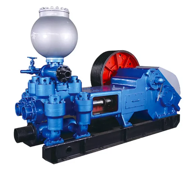
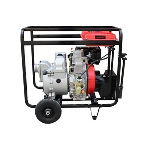
mud pump with diesel engine free sample

Explore a wide variety of mud pump with diesel engine on Alibaba.com and enjoy exquisite deals. The machines help maintain drilling mud circulation throughout the project. There are many models and brands available, each with outstanding value. These mud pump with diesel engine are efficient, durable, and completely waterproof. They are designed to lift water and mud with efficiency without using much energy or taking a lot of space.
The primary advantage of these mud pump with diesel engine is that they can raise water from greater depths. With the fast-changing technology, purchase machines that come with the best technology for optimum results. They should be well adapted to the overall configuration of the installation to perform various operations. Hence, quality products are needed for more efficiency and enjoyment of the machines" full life expectancy.
Alibaba.com offers a wide selection of products with innovative features. The products are designed for a wide range of flow rates that differ by brand. They provide cost-effective options catering to different consumer needs. When choosing the right mud pump with diesel engine for the drilling project, consider factors such as size, shape, and machine cost. More powerful tools are needed when dealing with large projects such as agriculture or irrigation.
Alibaba.com provides a wide range of mud pump with diesel engine to suit different tastes and budgets. The site has a large assortment of products from major suppliers on the market. The products are made of durable materials to avoid corrosion and premature wear during operations. The range of products and brands on the site assures quality and good value for money.
A wide variety of diesel engine mud pump options are available to you, such as 1 year, not available and 2 years.You can also choose from new, used diesel engine mud pump,as well as from energy & mining, construction works , and machinery repair shops diesel engine mud pump, and whether diesel engine mud pump is 1.5 years, 6 months, or unavailable.

As a manufacturer of diesel-driven pumps, BBA Pumps focuses on mobile pumps that are driven by a diesel engine. Our first diesel-powered pump was built in the 1970s and nowadays tens of thousands of BBA diesel sets are running worldwide in a wide variety of applications.
For pumps driven by modern diesel engines, the use of the correct fuel is crucial, not only during operation but also during storage. Information on the required fuel specifications can be found in the original manuals supplied by the engine manufacturer. It also contains important details about fuel additives such as Sulphur and FAME (Fatty Acid Methyl Esters).
All pumpsets with Hatz and Perkins diesel engines are approved to run on synthetic fuel according to the EN 15940 standard. Synthetic fuel includes the following products; GTL, CTL, XTL, BTL, and HVO. A blend with fossil fuels is also allowed, as long as the EN 590 or EN 15940 standards are met.
In some locations, your customer may require a certified spark arrestor. Depending on the pump model, a spark arrester is available as an additional option or even supplied as standard. For example, all Volvo Penta stage V powered BBA pump units come standard with a certified spark arrestor exhaust system.
A mobile BBA pump always covers the entire performance curve, meaning the diesel engine has sufficient engine power available for each operating point in the curve. The pump and motor can continuously run at full throttle without becoming overloaded.
Skid mounted units are becoming increasingly rare. Pumps in sound attenuated canopies are the new standard. The price difference is small, and the advantages are great: low noise, optimal safety, good protection against the elements and a high trade-in value.
BBA Pumps works with variable speed engines, allowing you to set the right pump speed for each job. Allowing you to save fuel, avoid unnecessary wear and tear and contribute to a cleaner environment.
Pump sets are only sent to the customer after the diesel engine manufacturer has successfully completed an official ‘certified installation’ audit. This means that all factory guarantees are in force and you can start using your pump without any worries.
Prevent unnecessary engine damage and make great cost savings.Always observe the fuel requirement, filters and maintenance intervals specified by the engine manufacturer. For pumps driven by a single-cylinder diesel engine (Hatz 1D90), BBA Pumps has developed the DriveOn® principle. This increases the service interval to 1500 operating hours.
A composite fuel tank is much less susceptible to condensation than a steel tank. The advantage is that the risk of diesel bacteria and pollution in the fuel system is minimal.
Almost every mobile diesel-powered BBA pump comes with a leak proof base. This prevents fuel or oil from ending up in the environment during refuelling or servicing.
With modern electronically regulated diesel engines, many parameters can be displayed via the engine management system. This information can be read easily and in several languages on the dashboard of the pump set.
The emission requirements for mobile pumps with diesel engines vary worldwide. BBA Pumps complies with emission legislation and has a compliant pump set available for each country.

OBS see new model. Diesel Mud pumps features 2-stage, 44 to 1 gear reduction with a large diameter output gear and heavy duty ball bearing construction. Often referred to as Mud pumps or Sludge pumps, diaphragm trash pumps are designed to pump mud, slurry, sewage, and thick liquids that have the ability to flow. Hatz Diesel engine 1B20.
Built-in molded polyurethane flapper/check valve assures self-priming to 20 feet after initial prime. Heavy duty gear box is designed to operate pumps at 40 strokes per minute for electric motor. Each unit includes a 3" NPT steel suction strainer, two 3" NPT nipples, and wheel kit with 10" semi-pneumatic transport wheels for portability. Pumps are designed for use with non-flammable liquids which are compatible with pump component materials. Suction and discharge port size cannot be reduced.
Suction and discharge port size cannot be reduced. Due to positive pumping action of diaphragm pumps, by all mfr"s, the discharge is recommended to only be 25FT long unless oversized. Discharge can not be restricted. There is no relief valve.

Usually it is necessary to pump every day until displacement depending on the pit size. Generally this would mean about five days of pumping pit fluid and cuttings prior to mud up. Once mud up occurs the pump will run about every other day through out the rest of the well. So for example, a 12 day well, would have 8 days pumping and 4 standby days for a total of $4,560.
Additionally, there would be approximately 100 gallons of diesel consumed at approximately $3 per gallon for $300. Set up and tear down is a total of $750 and average mileage would run an estimated $200. Typically overnight charges would be required for 5 nights which would be $375. Total pump charge for a typical well would be approximately $6,185.
We have now our possess revenue group, design staff, technical crew, QC team and package group. We now have strict excellent regulate procedures for each process. Also, all of our workers are experienced in printing subject for One of Hottest for China Energy-Saving Self Priming Diesel Water Pump, Our goods are strictly inspected before exporting , So we gain a excellent standing all around the planet. We wanting ahead to cooperation with you in the foreseeable future.
We have now our possess revenue group, design staff, technical crew, QC team and package group. We now have strict excellent regulate procedures for each process. Also, all of our workers are experienced in printing subject for China Water Pump, Self Priming Pump, We"re confident that we are able to deliver you with opportunities and are going to be a valuable business partner of you. We look forward to working with you soon. Learn more about the types of goods that we work with or contact us now directly with your inquiries. You are welcome to contact us anytime!

DAE Pumps dredging equipment is ideal for a variety of applications, including dredging dams, ports, marinas, rivers, canals, lakes, ponds, and more. Ensuring water quality and capacity are essential in hydroelectric and water supply dams, making DAE Pumps dredge pumps perfect for removing excess sand and silt. Clearing sediment and contaminates from riverbeds, channels, canals, and oceans help restore safe navigation and shoreline formations, and dredging lakes and ponds clean and remove contaminants and tailing. As ocean currents move sediments, the seafloor slowly rises, lowering the depth of marinas and ports. Dredging ensures safe access for boats and other water vessels.
Centrifugal pumps from DAE Pumps are perfectly suited for demanding process applications. Their heavy-duty construction ensures long-lasting performance in rugged conditions. The DAE Pumps knowledge and experience building top-of-the-line pumps make our centrifugal process pumps ideal in many markets and applications.
The durable DAE Pumps centrifugal pumps provide a proven ability to handle a variety of applications in the water and wastewater industries. These reliable instruments are perfect solutions for pumping chemicals used to treat water, irrigation, fountains, and much more.
For help selecting the most efficient pump for your project, call us at (760) 821-8112 or submit a request. Find the right pump size, volume, speed that you need. Get a FREE custom pump curve to ensure the right pump.
The motor or engine on a pump is as important as the pump itself. It is the driving force that makes the pump go. DAE Pumps offer a variety of motor choices: electric, diesel, and hydraulic.
Our close-coupled electric motors reduce the stress on motor bearings with a short shaft overhang and fan-cooled. Our submersible electric motors come completely enclosed with the most trusted watertight O-ring seals. Diesel engines offer self-priming features and easy to maintain capabilities. Hydraulic motors are powered by HPU or hydraulic power units and provide the utmost in capability and performance.
Frames and skids hold the pump and motor together to make a complete unit. The frame provides stability for the placement of the pump and motor with the intent of a permanent install or seldom movement. The DAE Pumps trailer brings mobility to centrifugal slurry pumps. The whole unit, skid included, is mounted onto a trailer for mobile accessibility. Many industries use centrifugal pumps for performing multiple applications, and they move from one location to another quite frequently. The trailer provides a tremendous advantage of being on wheels.
Centrifugal pumps come in many shapes and sizes. There are two main parts to a centrifugal pump; the pump and the motor/engine. The electric motor or a diesel engine converts the energy it creates into mechanical energy. This mechanical energy drives the pump and moves the water. The centrifugal slurry pumps pull water and other materials in through the inlet and pushes it out through the outlet/discharge.
The electric motor and diesel engine work relatively similarly. A motor consists of a fan and protective casing mounted at the back. Inside the motor is the stator. The stator holds copper coils. Concentric to this is the rotor and shaft. The rotor rotates, and as it spins, so does the pump shaft. The shaft runs the entire length of the motor and into the pump where it connects to the pump’s impeller.
There are a couple of variations to a centrifugal pump. Some models of centrifugal pumps have a separate shaft for the pump and the motor. The connection between the separated shafts is called the coupling. These coupled pumps will contain a bearing house with bearings. The pump shaft then continues into the pump casing. As it enters the casing it passes through a gland, packing, and the stuffing box, which combined to form a seal. The shaft then connects to the impeller. The impeller imparts centrifugal force onto the fluid that makes it to move liquids through a pipe or hose. The impeller is in the pump casing. The casing contains and directs the flow of water as the impeller pulls it in through the suction inlet and pushes it out through the discharge outlet.
At the back of the motor, the fan connects to the shaft. The motor rotates the shaft and fan. The fan cools down the motor/engine, and it blows ambient air over the casing to dissipate unwanted heat. If the motor becomes too hot, the insulation on the coils inside the motor melts, causing the motor or engine to short circuit and destroy itself. The fins on the outside perimeter of the casing increase the surface area of the casing, which allows for removing more unwanted heat. The motor comes in either three-phase or single-phase configuration, depending on the application.
At the center of this stator are the rotor and shaft. The rotor is affected by the rotating magnetic field and forces it to auto-rotate. The rotor connects to the shaft, which runs from the fan to the impeller. When the rotor rotates, so does the impeller. By creating the rotating magnetic field within the motor, the rotor spins the shaft and the impeller.
At the pump casing, there is a channel for water to flow along, which is called the volute. The volute spirals around the perimeter of the pump casing to the outlet. This channel increases in diameter as it makes its way to the outlet. The shaft passes through the seals and into the pump casing, where it connects to the impeller.
There are many types of impellers, but most have backward curved veins, which will either be open, semi-open, or closed. These backward-curved veins do not push the water. The curves rotate with the outer edge moving in the direction of the expanding volute. These veins will provide the fluid with a smooth path for the water to flow.
Liquid engulfs the impeller, and when it rotates, the fluid within the impeller also spins and is forced outward to the volute. As the fluid moves outwards, off of the impeller, it creates a region of low pressure that pulls more water in through the suction inlet. The fluids enter the eye of the impeller and are trapped there between the blades. As the impeller rotates, it imparts kinetic energy or velocity onto the liquid. By the time the liquid reaches the edge of the impeller, it is moving at a very high speed. This high-speed liquid flows into the volute where it hits the wall of a pump casing. This impact converts the velocity into potential energy or pressure. More fluid follows behind this developing a flow.
The thickness of the impeller and the rotational speed affects the volume flow rate of the pump and the diameter of the impeller, and the rotational speed increases the pressure it can produce.
Net Positive Suction Pressure or NPSH is associated with pump suction. At the end of this acronym are two other letters NPSHR and NPSHA. The R is the required NPSH. Each pump tests for this value. At DAE Pumps, we provide a pump operation chart with all our specs. The R-value is a warning or danger point. As the fluid enters the pump and flows into the impeller’s eye, it experiences a lot of energy due to the friction, giving a pressure drop. At certain conditions, the fluids flowing through this section can reach a boiling point. Once this happens, cavitation may occur.
The last letter in NPSHA stands for Available. The net positive suction pressure available depends on the installation of the pump and should be calculated. NPSHA takes into consideration things like insulation types, elevation, liquid temperature, liquid boiling point, much more. Available pressure should always be higher than the required value. For example, if the NPSHA is 12 for the pump requiring an NPSHR of 4 then the pump should be okay. However, a pump that required an NPSHR of 15 than the available NPSH is insufficient, and cavitation will occur.
DAE Pumps provides custom pump curves per the information you provide. Including as much information about the project allow us to best match a pump with your needs, so the centrifugal pump you get is ideal for the project.
Cavitation in pumps is the deterioration of the pump’s metal due to the overheating of water. Cavitation destroys the pump’s impeller and casing that lead to replacing parts and the pump altogether.
Water can turn from a liquid state into steam or gas and boils at around 100 degrees Celsius at sea level. However, at a higher elevation, water boils at a lower temperature because of atmospheric pressure. If this pressure is less than the vapor pressure of the liquid that is pumping, then the water can reach a boiling point. When this happens, cavitation occurs.
During cavitation, air particles within the water expand, and as they reach the boiling point, they collapse in on themselves very rapidly. As they collapse, they start to damage the impeller and pump casing. This damage removes small parts of metal from the surface, and if this keeps occurring, then it will eventually destroy the pump. Therefore, you must ensure the Available pressure is higher than the Required pressure of the pump.
DAE Pumps provides a full spectrum of centrifugal slurry pumps and accessories for completing all your tough dredging projects.We provide turnkey solutions with complete centrifugal slurry pump systems that includeslurry hoses, slurry flow meters, power units,and more.Choose from multiple sizes of slurry hoses for the transferring of materials, wireless flow meters for measuring the flow rate in gallons per minute of liquid, and power units for operation.Parts are always in stock and available for immediate shipping to anywhere in the US and the world.

This invention relates to the circulation of fluid between the surface of a subterranean well and the bore hole and more specifically relates to the simultaneous control of drilling fluid circulation or mud pumps and a choke communicating with the pump.
Conventional apparatus used in rotary drilling operations includes a drilling fluid circulation pump or mud pump used to circulate drilling fluids from the surface through the well bore. These fluids are used to remove cuttings made by a rotary drill. In normal drilling fluid or mud circulation, the drilling fluid is pumped down through the drill pipe, discharged through the bit and returns to the surface in the annular space outside the drill pipe and inside the drill hole and casing placed in the well. The rate of drilling fluid circulation is determined by the necessary upward flow velocity required for removing cavings and drill cuttings from the hole and by the jetting requirements of the bit. The inherent advantage of the rotary system of drilling is that a fluid is circulated for the purpose of removing drill cuttings and maintaining a hole in such condition that the drill string can be withdrawn readily and returned to the bottom whenever necessary.
During conventional drilling it is not uncommon to encounter a sudden pressure increase or kick caused by the release of downhole liquids or gases under pressure which can affect drilling fluid circulation. When a kick is encountered, it can be necessary to vary the rate at which drilling fluid is injected into the well or to change the weight of the drilling fluid. A choke, in communication with the pump, is used to prevent significant pressure changes in conjunction with a change in the speed of operation of the mud pumps. For example, a significant increase in downhole pressure occurring as a result of an increase in the drilling fluid circulation can conceivably fracture the producing formation causing serious damage.
In normal drilling operations, the mud pumps are controlled by the driller, using a driller"s console located at the driller"s station on a rig to monitor relevant drilling parameters, including the speed of the mud pumps. Furthermore, conventional well control circulation operations also require manipulation of the choke to regulate or control the fluid pressure, especially during changes in the speed of the mud pump. On a conventional drilling rig, the choke is normally controlled from a choke console, which can be positioned on the drilling floor, at a position remote from the normal location of a driller"s console on a surface rig. Simultaneous control of both the mud pumps and the choke requires communication between the driller and one manning the choke console. Such communication is difficult, especially on engine driven drilling rigs. The noise and the use of different types of gauges on a rig cause confusion and makes such communication difficult, especially on engine driven drilling rigs. Furthermore, a more accurate gauge for pump strokes rate is conventionally located at the choke console, but conventional apparatus provide no means for using this more accurate gauge at the choke console to control the pumps. In a crisis situation, where the drilling crew is attempting to control the well, increased emphasis is placed on efficient communication and operation, which is difficult using prior art devices.
Apparatus for controlling the circulation of well control or kill fluid in a subterranean well includes a pump and a choke communicating with the pump to deliver drilling fluids from the surface of the well into the bore hole and return to the fluid handling equipment. Apparatus for monitoring the condition of the pump is normally employed at the driller"s console on the drilling rig and such pump monitoring apparatus includes a conventional pump control for regulating the speed and operation of the drilling fluid pumps. These pump controls can consist of pneumatic control valves or rheostats.
While control of the pump can be effected from the driller"s console, control of the choke can be simultaneously effected using a choke control apparatus located at a choke console, normally located on the drilling floor at a location remote from the driller"s console. A second pump control apparatus, again consisting of a conventional device, such as a pneumatic control valve or a rheostat, is located at the choke monitoring console and can be used to regulate pump speed and operation in the same manner as the first pump control apparatus located at the driller"s console. Apparatus is provided for overriding the first pump control upon transmission of a signal from the second pump control. Such apparatus can comprise a pneumatic valve unit or an electrical relay consisting of normally closed and normally open switches which change state upon actuation of the second pump control apparatus. In the preferred embodiment of this invention, the overriding signal is the same as the pump control signal. When this pump control signal is transmitted, a valve or relay functions to override the first pump control apparatus. Signals transmitted from the second pump control located at the choke console can then be transmitted to the pumps.
In the preferred embodiment of this invention, the overriding apparatus comprises a portion of an interface network located in the driller"s console, and the second pump control signal is transmitted from the choke console through the driller"s console and subsequently to the drilling fluid or mud pumps. In this manner, control of both the pump and the choke can be transferred to the same location on the drilling rig to provide for better control over both the rate of circulation of the drilling fluids and over the pressure maintained in the bore hole. Such centralized control is quite useful in certain situations, such as when a kick is encountered.
The preferred embodiments of the invention depicted herein are intended for use with conventional driller"s consoles and choke consoles employed on diesel or electrically powered rigs commonly used for drilling subterranean wells. The interface network and remote pump control apparatus employed in the choke console are consistent with conventional commercially available components of driller"s consoles and choke console.
FIG. 1 shows the conventional location of the driller"s console 2 and choke console 4 between which signals are transmitted to regulate or control both mud pumps 6 and the choke 8. The choke console 4 located proximate to the choke 8 separately controls the operation of the choke. The driller"s console 2 includes means for separately controlling the mud pumps 6 and signals may be transmitted from the choke console to the driller"s console for regulating the operation and speed of the mud pump. It can be seen from FIG. 2 that in the preferred embodiment of this invention the choke console controls the pumps by signals transmitted through the driller"s console 2. The transmission of signals between the various components shown in FIG. 2 can be by any of a number of conventional means, such as by electrical signals, by pneumatic or hydraulic signals, by fiber optic signals, by power line modulation, or in any other conventional form suitable for use on a drilling rig. A pneumatic control network for use with a diesel powered rig and an electrical interface network for use within an electrically powered drilling rig will be described herein.
FIGS. 3-5 depict the operation of a pneumatic interface network for a diesel powered rig. Only those portions of the pump control and the interface network relevant to the control of drilling fluid, circulating or mud pumps are depicted. Numerous other components are employed in a driller"s console or in a choke console. Such components are, however, conventional and the components shown in FIG. 3 are compatible with other conventional components controlling the operation of a drilling rig. The pneumatic interface network for the diesel powered rig shown in FIG. 3 is intended for use in controlling two mud pumps. On conventional drilling rigs, two or more mud pumps are employed, although it is common practice to use only a single mud pump at a time, retaining the other mud pumps for redundancy and/or for emergency situations. The two pneumatic control valves 12 and 26 contained within the driller"s console comprise conventional valves commonly employed in driller"s console. Valves manufactured by American Standard having a pressure range of 0 to 100 psi for clutch and throttle signals represent one conventional valve for controlling the mud pump. A plurality of shuttle valves 18, 20, 32 and 34, each comprising a dual input-single output valve, are employed on opposite sides of each of the first or main pneumatic control valves 12 and 26 for controlling the operation of the mud pumps. Shuttle valves 18, 20, 32 and 34 may comprise conventional valves, such as the P-54350-2 shuttle valve manufactured by Wabco, an American Standard Company. Of course other similar valves could be used to form the isolation function of these shuttle valves. Valve 70, also located at the driller"s console, comprises a four element stack valve unit consisting of valve elements 70a, 70b, 70c and 70d. Pneumatic valves 70 each comprise spring loaded, dual input, single output valves forming a valve stack 70. Individual valves are of conventional construction and comprise valves such as the A222PS valves manufactured by ARO Inc. which can be secured together by using an MKN stacking kit and an isolator plate manufactured by ARO Inc.
The pneumatic control valve 46 employed in the choke console comprises, in the preferred embodiment of this invention, an HD-2-FX pneumatic control valve having a pressure range from 0 to 100 psi, manufactured by American Standard. Pneumatic control valve 46 has a single input and three separate outputs. Valve 46 is located in the choke console and communicates with a conduit 40 providing air under pressure for use in actuating the various components depicted herein. A toggle switch 42 and an indicator light 44 are located on the choke console to insure that control is not transferred between the choke console and the driller"s console at a time when the differences in the throttle settings between the choke console and the driller"s console will create a serious pressure increase below the well, thus damaging the formation.
Three conduits 48, 50 and 52 extend from pneumatic control valve 46 to the driller"s console. Conduits 50 and 52 comprise the clutch C1 and clutch C2 signal paths for controlling the chokes 8 and communicate between the pneumatic control valve 46 and the individual valve units of stack valve 70. Clutch C1 line 52 is interconnected to shuttle valve element 20 and clutch C2 transmission line 50 is interconnected to shuttle valve 32. A T-conduit 54 is interconnected to the clutch C1 line 52 intermediate its ends and the T-conduit 54 establishes fluid communication between the clutch C1 line 52 and the first valve unit 70a. A separate branch 56 establishes communication between T-conduit 54 and another unit 70d of the stack. Each of the stack valves 70a-70d comprises a normally spring loaded valve in which the input from either rig air conduit 64 or from throttle valve line 48 passes directly through valve units 70a-70d. The T-conduit 54 and its adjoining conduit 56 lead from clutch line 52 and communicate with an actuator port on valve units 70a and 70d. Fluid pressure in conduit 54 and 56 serves to shift the pneumatic valve units 70a and 70d to close lines 64 or 48 when pressure is applied to clutch C1 conduit 52.
The clutch C2 line 50 extends the pneumatic control valve 46 into the driller"s console and communicates with shuttle valve 32. A T-conduit section 58 and branch 60 communicate with clutch C2 line 50 and with the remaining two valve units 70b and 70c at the actuator ports thereof. Pressure in clutch C2 line 50 will cause the valve units 70b and 70c to close against the action of a spring similarly disrupting the input from conduit 64 or 48 respectively.
The rig air input from conduit 64 into stack valve units 70a and 70b passes through lines 66 and 68 respectively to the pump control valves 12 and 26 when stack valves 70a and 70b are in the open position. Essentially, the stack valve units 70a and 70b are connected in parallel to the rig air source 64. The output conduits 61 and 62 leading from the stack valve units 70c and 70d are respectively connected to shuttle valves 18 and 34. Communication is normally established between throttle line 48 and valves 18 and 34 through the stack valve units 70c and 70d when the spring loaded valves are in their normally open position.
The first pneumatic control valves 12 and 26 comprise conventional elements for generating clutch and throttle signals in response to a constant pressure supply or rig air in conduit 64. For example, valve 12 generates a clutch signal in line 14 and a throttle signal in line 16. Clutch line 14 communicates with one of the two input ports of shuttle valve 20. Throttle line 16 communicates with one of the two input ports of shuttle valve 18.
FIG. 3 depicts a condition in which the mud pumps 6 and 6" can be controlled by using the first or primary mud pump controllers 12 and 26. It should be understood that in an actual practice, only one pump is normally used. Solid lines have been used to indicate that pneumatic signals communicate through the line, while dashed lines indicate that the line has been disabled and no signal is transmitted. As shown by the solid lines in FIG. 3, pressure in line 64, which is obtained from a source of rig air, communicates through the normally open stack valves 70a and 70b to lines 66 and 68 respectively. Rig air is then applied to pneumatic control valves 12 and 26. Referring to control valve 12, the presence of rig air at the input of this first control valve permits clutch and throttle signals to be generated in lines 14 and 16 respectively. Since the choke console pneumatic control valve is in the off position, as shown in FIG. 3, and there is no pressure in lines 48, 50 and 52, a pneumatic signal is applied in only one of the dual input ports of shuttle valves 18 and 20. A pneumatic clutch signal in line 14 can be transmitted through shuttle valve 20 and clutch line 22 directly to the drilling fluid or mud pump. Similarly, a throttle signal in line 16 would be transmitted through shuttle valve 18 and line 24 to the pump. Thus the pneumatic throttle and clutch signals to pump 6 are employed to control the operating speed of an internal combustion engine, for example, driving pump 6 and an operating clutch to engage or disengage the pump as desired or required.
FIG. 4 shows the condition in which the choke console pneumatic control valve 46 is actuated to apply a pneumatic signal in clutch line 52 and in throttle line 48. Pneumatic control valve 46 is of the type that actuation of a control lever in one direction will induce a clutch signal during initial movement and thereafter will produce a throttle signal. The pneumatic signal in clutch line 52 acts through lines 54 and 56 on the actuator ports of stack valve units 70a and 70d. Pressure applied at the actuator ports plugs the input lines to stack valve units 70a and 70d. Thus the rig air from line 64 is plugged by stack valve unit 70a thus disabling the first mud pump control valve 12 which comprises the primary means of regulating the mud pump 6 from the driller"s console. The pneumatic signal in line 52 is, however, transmitted to the second input port of shuttle valve 20. Since there is no pressure in line 14, any clutch signal in line 52 at shuttle valve 20 will be transmitted through line 22. The pneumatic signal in line 52 communicating with line 56 also disables the throttle input to stack valve unit 70d isolating shuttle valve 34 from the throttle line 48. Stack valve unit 70c, however, remains open and the pneumatic signal in throttle line 48 will be transmitted through line 61 to shuttle valve 18. This pneumatic signal in line 61 is in turn transmitted through throttle line 24 to the first mud pump. Similarly, the stack valve unit 70b remains open and rig air from conduit 64 flows through line 68 to the secondary driller mud pump control valve 26.
FIG. 5 shows the same pneumatic control circuit in which the choke console pump control valve 46 has been actuated to generate a pneumatic clutch C2 signal in line 50. This pneumatic signal in line 50 communicates through lines 58 and 60 to the actuating ports of stack valve units 70b and 70c to close the input ports from the rig air conduit 64 and from the throttle line 48 respectively. Valve units 70a and 70d, however, remain open. Rig air can thus be applied to pump control valve 12 and the pneumatic signal in throttle line 48 can be transmitted through stack valve unit 70d to one input port of shuttle valve 34. Similarly, the pneumatic signal in clutch C2 line 50 is transmitted to an input port of shuttle valve 32. A clutch signal derived from the pneumatic control valve 46 can thus be applied through line 36 to the second mud pump. Similarly, a throttle signal 38 determined by the position of pneumatic control valve 46 can be applied through shuttle valve 34 and line 38 to the second mud pump. Choke console pneumatic control valve 46 is of the type that actuation of an input lever in a first direction will apply a signal in clutch C1 line 52 and in throttle line 48, while actuation of the control valve unit in the opposite direction will result in the presence of a pneumatic signal in clutch C2 line 50 and in the throttle line 48. It will be understood that separate choke control elements are contained within the choke console for positioning the choke in the proper position. When the apparatus is in the configurations of FIGS. 4 and 5, the choke control valve 46 can also be used to control either mud pump 6 or mud pump 6".
FIG. 6 shows an electrical interface network for use with an electrically powered rig. Again, separate drillers and choke consoles can be used in the same manner as shown in FIG. 2. In this electrically powered network, rheostat 72 provides a control signal through path 88 and normally closed relay 84a and line 86 to an SCR housing for controlling the operation and speed of a single mud pump. A second rheostat 90 located on the choke console is normally isolated from SCR housing line 86 by a normally open relay 84b. The configuration of FIG. 6 shows the conventional operation of the mud pump 6 by means of the pump controlling rheostat 72 located in the driller"s console. When it is desired to control the mud pump by use of the choke mud pump control rheostat 90, switches 76 and 77 are closed. When switch 76 is closed, the relay 84 changes state and the normally open relay 84b is closed permitting regulation of the mud pump by the choke console mud pump rheostat 90. Closure of switch 76 results in the application of a voltage to the relay 84 thus changing the state of relays 84a and 84b to override the signal from the driller"s console mud pump rheostat 72 when it is desired to control the mud pump from the remote position of the choke console. Note that the common +V line 80 and ground line 82 lead between the driller"s console and the choke console. If for any reason these lines are severed, control of the mud pump automatically reverts to the driller"s console rheostat 72. Thus, the mud pump 6 or mud pump 6" can be controlled from the driller"s console or through the remote position of the choke console depending upon closure of electrical switch 76.
Although the invention has been described in terms of the specified embodiments which are set forth in detail, it should be understood that this is by illustration only and that the invention is not necessarily limited thereto, since alternative embodiments and operating techniques will become apparent to those skilled in the art in view of the disclosure. Accordingly, modifications are contemplated which can be made without departing from the spirit of the described invention.

Mud Pumps come in both electric and gas / diesel engine drive along with air motors. Most of these pumps for mud, trash and sludge or other high solids content liquid dewatering, honey wagon and pumper trucks. Slurry and mud pumps are often diaphragm type pumps but also include centrifugal trash and submersible non-clog styles.
WARNING: Do not use in explosive atmosphere or for pumping volatile flammable liquids. Do not throttle or restrict the discharge. Recommend short lengths of discharge hose since a diaphragm mud pump is a positive displacement type and they are not built with relief valves.


 8613371530291