
seat puller mud pump pricelist
We are a leading Manufacturer of Mud Pump Spare, Duplex Mud Pump Parts, Mud Pump Valve Guide And Spring, SS Gland Flange, Mud Pump Spanner And Puller and Pinion Gear from Mehsana, India.
With great zeal and enthusiasm, our quality certified entity is successfully committed in manufacturing, exporting and supplying optimum quality range of Mud Pump Valve Guide And Spring.Our highly experienced team of professionals manufacture these products with the use of premium grade raw materials. Especially used in mud pumps for controlling the flow of liquids, the offered products are made available in different sizes and finishes. Also, checked by quality experts on various aspects, the provided Mud Pump Valve Guide AndMud Pump ValveSpringat reasonable prices from us.
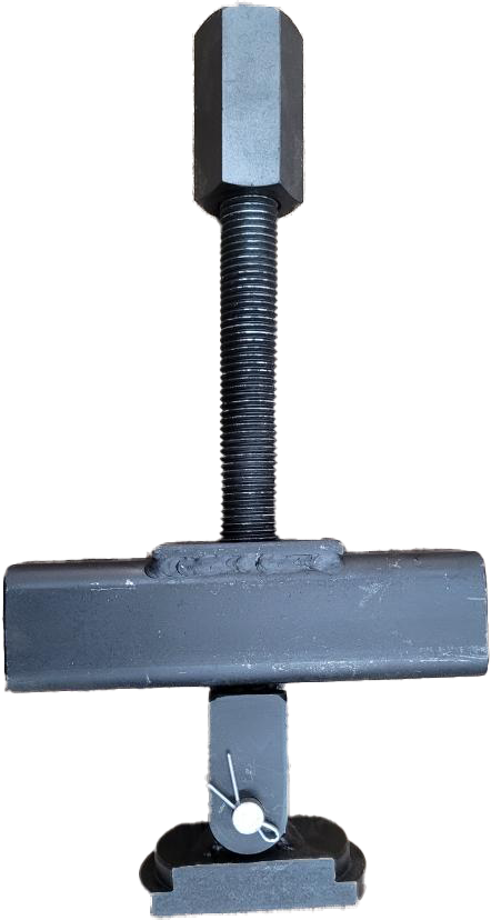
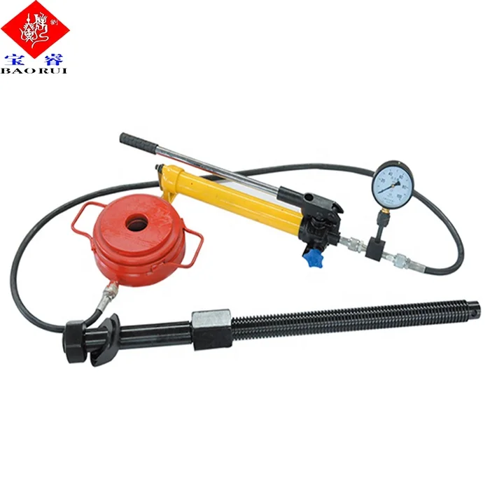
We are a quality conscious enterprise, successfully engaged in manufacturing, exporting and supplying the best grade of Mud Pump Spanner And Puller.The offered puller is manufactured at our premises with the use of supreme grade raw materials as per international quality standards. The provided spanner with puller is widely used for installation in mud pumps in order to ensure its smooth operations. Additionally, we provide this Mud Pump Spanner AndMud PumpPullerat marginal prices to our clients.
Established in 1991, Laxmi Pumps Private Limited has been producing LADA Submersible Pumps exclusively with reliable quality and excellent after-sales service. LADA is the brand under which our products are manufactured and marketed.
Established in 1991, Laxmi Pumps Private Limited has been producing LADA Submersible Pumps exclusively with reliable quality and excellent after-sales service. LADA is the brand under which our products are manufactured and marketed.
We are one of the renowned Manufacturers, Exporters and Suppliers of precision-engineered Mud Pumps in Gujarat (India). Our LX-series of Mud Pumps sold under the brand name “Laxmi” is manufacturing in compliance with international standards as our company isISO 9001: 2008 certified.
Developed by a team of highly qualified engineers using computer-aided designing and manufacturing technologies, our Mud Pumps are double-acting and piston (reciprocating) type. They are designed to endure high pressure and high discharge application. In addition, they have several in-built design and constructional features that ensure high efficiency without much electricity intake.
Our Mud Pumps are available in various models and can be ordered in bulk. In addition, we offer them at very economical prices and provide customized solutions.
Our Mud Pumps are duplex double acting reciprocating type made from a single piece alloy casting capable of handling high discharge and high pressure applications. These are ideally suitable for seismograph survey, water well, oil well, core drilling mud and cement service applications. Moreover, the pumps feature continuous tooth herring-bone gears fitted with eccentric for easy economical replacement.
We have the requisite technical and commercial expertise to expand our business to new horizons of growth. Company’s main strength is its Quality and Innovative designs. This is the reason why our products are well established as POWERSAVER PUMPS in the market.

GD Energy Products understands the demands of the oil & gas industry and its multiple pumping applications. We spent more than a year and worked directly with our customers to develop the best valves and seats in the oilfield. Customers said they wanted long-lasting, easy-to-use valves and seats, and we delivered. From the designs and materials, to our state-of-the- art manufacturing processes, our products are made to be the most durable on the market.
Our valves and seats are color coded for maximum ease of use in every stage of replacement. Each box has a product photo and corresponding label color to make replacement easier for every person involved in ordering, stocking or installing expendables.
GD Energy Products valves and seats are manufactured in Fort Worth, Texas and inventory is stocked throughout our facilities across the U.S. for immediate availability. Customer consignment programs are also available for high volume usage.

In general, the present invention relates to an apparatus and system for removing seats. More particularly, the present invention provides an improved puller that utilizes spring loaded J-shaped hooks for removing various seats, valve seats, pump liners and so forth from oilfield fracturing pumps, mud pumps, nitrogen pumps, and other equipment found in the oil and gas industry as well as other equipment utilizing same. It is also understood the current invention may be utilized in any other pump type that utilizes replaceable open face seats.
Due to the nature of seats in general, it is often extremely difficult to remove the seat after it is installed. There are many prior art devices for pulling pump valve seats and liners, but most of them are complex and expensive. If a valve seat puller is complex, it consumes time in the removal of the valve seat which translates into money lost during the down time. It is not unusual for the down time in removing a valve seat with prior art devices to run 8-20 hours.
It is understood that in various piston type reciprocating pumps there are valves which open and close in order to direct the flow. The valve mates to a replaceable seat in order to create a seal, stopping the fluid which is being pumped, moving in the direction it is being forced. Over time with the opening and closing of the valves against seat creates wear causing the valves not to seal. The common term used for worn seats is “washed”. At this time, the seats must be replaced with new ones.
Valve seats in most pumps are generally slightly tapered, with or without an o-ring, for sealing the seat to the pump head. They are typically held in place by the taper, in that they are pressed into place. When a seat is replaced, it is removed with a puller. There are several different types of pullers used which include a two half puller that spreads out to the inside dimension of the seat by threading the puller shaft inside it, opening the two outer halves far enough to catch the bottom of the seat. This is typically done by two people where one lowers the puller shaft down through the seat, while another person reaches the two half parts of the puller through an open port in the head. The person with the threaded shaft then attempts to thread the puller shaft into the expandable halves. A hydraulic jack, such as hollow shaft jack, is then generally utilized to pull the shaft.
Another commonly used puller is a flat plate that hinges on the bottom of the puller body. It is tipped vertically and then inserted through the seat where gravity causes the flat plate to fall horizontally, thus catching the bottom of the seat and pulled with the same hydraulic jack. These types of pullers fail regularly in that they will not withstand very high pulling pressures. The normal practice at this point, when the pullers have failed, is to call a welder to cut the seat out of the pump with an acetylene torch. This naturally exposes the head of the pump to be “nicked” or cut into with the torch that can cause the head to have to be removed and taken to be repaired.
Another example of a prior art valve seat puller is U.S. Pat. No. 3,990,139 issued to Touchet on Nov. 9, 1976. This device utilizes J-shaped hooks wherein the hooks are essentially individual pieces that work in cooperation and are hinged at the top portion to allow the hooks to spread out and engage the valve seat when in position. These J-shaped hooks are not spring loaded and therefore require a mechanical means to spread the hooks out to engage the seat. More specifically and quoting the issued patent, one embodiment of the pipe pulling apparatus 10 comprises a plurality of J-shaped hooks 24 having a J-shaped end or head 26 and a transverse T-shaped other end 25. The hooks 24 are pivotally supported by its T-shaped end 25 in radial slots 33 of support block or plate 22. In another embodiment, the J-shaped hooks are supported in slots 61 in support block 54 by a transverse T-shaped head portion 57, with the opposite end having a J-shaped head 59 for engaging the lower rim of valve seat 52 when pivoting.
This prior art device has several inherent problems due to the configuration of the individual J-shaped hooks and need for the hooks to pivot by a mechanical means. Needless to say any obstruction in the pivot movement would prevent the J-shaped hook from rotating out for extending and thus would not allow for the hook to catch the valve seat. Dirt and debris in the field associated with the use of pumps is more common than not and frequently inhibited the hook from pivoting as needed. Also of note, rust would frequently inhibit the pivot movement requiring cleaning and lubricating of the part to keep it from binding.
Furthermore, sometime the hook would be stuck in the extended position because the pivot problem. This would mean that the J-shaped hook would not pass through the valve seat opening and often would cause further damage when hitting the valve seat. It is not uncommon for the stuck out J-shaped hook to further push down the seat, damage, it and so forth making it even more difficult to remove.
Still furthermore, the prior art device of U.S. Pat. No. 3,990,139 essentially utilizes a threaded shaft to spread the J-shaped hooks as well as to extract the seat once engaged by use of rotational force for lifting. Current valve seats are typically seated in a tighter fashion making the torque required to rotational lift extremely high which leads to failures, stripping of threads, and damage to motors needed to provide the rotational movement.
It is therefore desirable to provide a valve seat puller and or extractor that provides a spring function to spread the j-shaped hooks to engage the seat when desired and eliminate the need for a mechanical system to engage the hooks. It is also desirable to provide a puller that may be utilized with a hydraulic jack to pull the seat up and out without the need for rotational lifting.
Present day drilling operations are extremely expensive, and an effort to increase the overall efficiency of the drilling operation while minimizing expense requires the essentially continuous operation of the drilling rig. Thus, it is imperative that downtime be minimized. The above discussed limitations in the prior art is not exhaustive. Thus, there is a need for an apparatus, method and system to remove valve seats, pump liners, and so forth easily and quickly. The current invention provides an inexpensive, time saving, more reliable apparatus and system where the prior art fails.
In view of the foregoing disadvantages inherent in the known types of pullers now present in the prior art, the present invention provides a new and improved apparatus and system which is easier to utilize and more time efficient. As such, the general purpose of the present invention, which will be described subsequently in greater detail, is to provide a new and improved seat puller apparatus and system for replacing seals which has all the advantages of the prior art devices and none or fewer of the disadvantages.
To attain this, the present invention essentially comprises a new and improved assembly that utilizes spring loaded J-shaped hook made from a metal that provides sufficient strength for forces required to pull out the seat, pump liner and so forth, flexible enough to bend as needed to enter the seat, and yet still rigid enough to return to its natural state for repeated use. The invention may be utilized for removing various seats, valve seats, pump liners and so forth from oilfield fracturing pumps, mud pumps, nitrogen pumps, and other equipment found in oil and gas industry as well as other equipment utilizing same. It is also understood the current invention may be utilized in any other pump type that utilizes replaceable open face seats.
Therefore, it is an object of the present invention to provide a new and improved apparatus, system and method for removing and or pulling seats, pump liners, and so forth which may be easily and efficiently utilized.
It is a further object of the present invention to provide a new and improved apparatus, system and method for removing seats, pump liners, and so forth, which is of a durable and reliable construction and may be utilized with multiple types of applications in the oil and gas field as well as other applications.
An even further object of the present invention is to provide a new and improved apparatus, system and method for removing seats, pump liners, and so forth which is generally susceptible to a low cost of manufacture with regard to both materials and labor, and which accordingly is then susceptible to low prices of sale to the consuming industry, thereby making such tool economically available to those in the field.
Still another object of the present invention is to provide a new and improved apparatus, system and method for removing seats, pump liners, and so forth which provides all of the advantages of the prior art, while simultaneously overcoming some of the disadvantages normally associated therewith.
Another object of the present invention is to provide a new and improved apparatus, system and method for removing seats, pump liners, and so forth that does not require a conventional spring assembly and has fewer moving parts than prior art devices.
Yet another object of the present invention is to provide a new and improved apparatus, system and method for removing seats, pump liners, and so forth that may allow for one individual to operate, may be operated with no one having to reach inside a pump head, and generally reduces the risk of injury.
Still another object of the present invention is to provide a new and improved apparatus, system and method for removing seats, pump liners, and so forth which increases the speed of the replacement operation regarding changing out of associated parts.
An even further object of the present invention is to provide a new and improved apparatus, system and method for removing seats, pump liners, and so forth that provides a robust device capable of extreme and numerous uses and may generally withstand much greater amounts of pressure than existing pullers known in the art.
FIG. 1 is generally a depiction of a preferred embodiment of the invention generally showing a partially exploded perspective view of spring catch 20, bottom nose 30, puller shaft 40, and sleeve 50 in accordance with the current invention.
FIG. 2 is generally a depiction of a preferred embodiment of the invention generally showing a cutaway side view as utilized in a pump and generally depicting spring catch 20 bottom 220 and or segment(s) 260 distal end(s) 270 passing through valve seat 90 after compression of spring catch 20 in accordance with the current invention.
FIG. 3 is generally a depiction of a preferred embodiment of the invention generally showing a perspective view of spring catch 20, bottom nose 30, puller shaft 40, and sleeve 50 wherein spring catch 20 is generally in an upward position sleeve 50 in accordance with the current invention.
FIG. 4 is generally a depiction of a preferred embodiment of the invention generally showing a perspective view of spring catch 20, bottom nose 30, puller shaft 40, and sleeve 50 wherein spring catch 20 is generally in a downward position relative to sleeve 50 and bottom 220 of spring catch 20 in communication with bottom nose 30 recessed lip portion 280 in accordance with the current invention.
FIG. 5A is generally a preferred embodiment of the invention depicting spring sleeve 20 in compression as it passes through valve seat 90 in accordance with the current invention.
FIG. 5B is generally a preferred embodiment of the invention depicting spring sleeve 20 after it has passed completely through valve seat 90 with spring catch 20 no longer in compression in accordance with the current invention.
FIG. 5C is generally a preferred embodiment of the invention depicting spring sleeve 20 after it has passed completely through valve seat 90 with spring catch 20 no longer in compression and in communication with valve seat 90 as jack 200 is lifting to remove valve seat 90 in accordance with the current invention.
FIG. 5D is generally a preferred embodiment of the invention depicting spring sleeve 20 after it has passed completely through valve seat 90 with spring catch 20 no longer in compression and in communication with valve seat 90 after jack 200 has lifted and removed seat 90 in accordance with the current invention.
FIG. 6A is generally a depiction of a preferred embodiment of the invention generally showing a bottom view where in spring catch 20 is in compression and passing through valve seat 90 while bending into smaller circumference 165 in accordance with the current invention.
FIG. 6B is generally a depiction of a preferred embodiment of the invention generally showing a bottom view where spring catch 20 is no longer in compression and returned to original circumference 175 thus allowing J-shaped hooks 160 to engage the lower rim 110 of valve seat 90 for pulling upward and out in accordance with the current invention.
FIG. 7 is generally a preferred embodiment of the invention depicting spring sleeve 20 after it has passed completely through valve seat 90 with spring catch 20 no longer in compression and in communication with valve seat 90 after jack 200 has lifted and removed valve seat 90 in accordance with the current invention. This depiction is essentially a larger image of FIG. 5D.
FIG. 8 is generally a preferred embodiment of the invention depicting spring sleeve 20 after it has passed completely through valve seat 90 with spring catch 20 no longer in compression in accordance with the current invention. This depiction is essentially a larger image of FIG. 5B.
FIG. 9 is generally a preferred embodiment of the invention depicting spring sleeve 20 after it has passed completely through valve seat 90 with spring catch 20 no longer in compression and in communication with valve seat 90 as jack 200 is lifting to remove valve seat 90 in accordance with the current invention. This depiction is essentially a larger image of FIG. 5C.
Referring to the illustrations, drawings, and pictures, reference character 10 generally designates a new and improved puller device, assembly, system and method of using same constructed in accordance with the present invention. Invention 10 is generally used in oil and gas well operations but may be utilized in other applications. The current invention should not be considered limited to just seat, valve seat, pump liners, and so forth removal.
Now Referring to the illustration and more in particular to FIG. 1, invention 10 may include spring catch 20, bottom nose 30, puller shaft 40, and sleeve 50 generally positioned axially as depicted in the illustrations as will be discussed further below.
Again referring to the drawings in general and more specifically to FIG. 2, invention 10 may generally be utilized with a pump assembly 60. A portion of the invention 10 is generally depicted being inserted into opening 70 of a pump or pump head 80 for engaging stuck valve seat 90. Valve seat 90 comprises an outer diameter or ring 100 having a lower rim or bottom face 110 and an inner diameter or ring 120. The inner diameter 120 has an aperture 130. Valve seat 90 may also include a top face or portion 140 having an angled surface 150.
Spring catch 20 is generally formed of J-shaped hooks 160 that allow for flexing and or bending. A preferred embodiment is of a one piece construction having twelve (12) J-shaped hooks 160 although more or less J-shaped hooks 160 may be utilized. The spacing between the J-shaped hooks 160 generally allows for the circumference to be made smaller when the J-shaped hooks 160 are compressed such as but not limited to bending into a smaller circumference 165. The spring quality of the design allows for the J-shaped hooks 160 to return to the original spacing when not compressed such as but not limited to going back to the original circumference 175. Puller shaft 40 may generally be threaded and utilized to hold spring catch 20 and sleeve 50. It may be rotated for the desired lifting and lowered from above by hydraulic means, mechanical means, and combinations thereof. Invention 10 contemplates utilization with a hydraulic jack puller shaft 40 may be made of steel known in the industry and have threading known in the industry. Puller shaft 40 may generally comprise a top or top portion 170 that may attach to a nut 180 for holding puller shaft 40 in a relatively fixed position in opening 70 of pump head 80 while allowing the puller shaft 40 to move up and down as desired. The movement may be accomplished through hydraulic, mechanical and combinations thereof as known in the art. Bottom or bottom portion 190 of puller shaft 40 may generally be utilized to removably hold bottom nose 30.
Bottom nose 30 may be made from steel and or other materials known in the art. Bottom nose 30 may generally be removably threaded onto and axially aligned with puller shaft 40 bottom portion 190. It is understood that numerous types of removable connections to puller shaft 40 are contemplated.
Sleeve 50 may also be constructed from steel and other materials known in the art. It is contemplated that sleeve 50 is generally fixed axially on puller shaft 40 and generally holds spring catch 20 and allows spring catch 20 to move up and down, relative to puller shaft 40, while being trapped at the top of spring catch 20 inside sleeve 50. Generally this configuration provides a “floating” spring catch 20 inside sleeve 50. It is also contemplated that invention 10 may not utilize sleeve 50, sleeve 50 may be incorporated into spring catch 20, sleeve 50 may be generally non-movably fixed to spring catch 20, combinations thereof, and so forth. Sleeve 50 may generally look like a cup and or cap fixed and or removably fixed on puller shaft 40 with threads, welds, and so forth.
Now again refereeing to the illustrations and more in particular to FIGS. 3 through FIGS. 9, generally, the puller shaft 40 is inserted in through the valve seat 90 from the top of the pump head 80 by inserting the puller shaft 40 bottom nose 30 down hole or opening 70 until bottom nose 30 passes valve seat 90 and sleeve 50 contacts top of valve seat 90 bringing puller shaft 40 essentially to a stop. Sleeve 50 may also generally function as a general guide for passing spring catch 20 through the pump assembly 60 as well as an indicator when the puller shaft 40 has descended far enough into the pump assembly 60 to engage valve seat 90.
It is then contemplated that a hollow shaft hydraulic jack 200 is put onto the puller shaft 40 and secured by nut 180. At this point, the valve seat 90 is pulled by the hydraulic jack 200 upward. It is contemplated that invention 10 will allow for a generally vertical removal of valve seat 90 without the need for a rotational force as the prior art devices. It is also contemplated that puller shaft 40 may not be threaded. It is still further contemplated that top or top portion 170 of puller shaft 40 may be formed and or adapted to attach and or communicate with a hydraulic jack 200 as known in the prior art.
The improved design of invention 10 generally pushes steel spring catch 20 through valve seat 90 and then springs back once passing the bottom face 110 of valve seat 90. J-shaped hooks 160 are essentially forced into bending into a smaller circumference 165 as the downward force on spring catch 20 contacts with the angle of surface 150 of valve seat 90. After the J-shaped hooks 160 clear the bottom face 110 of valve seat 90, they are allowed to spring back and or unbend to the original circumference 175 thus allowing the J-shaped hooks 160 to engage the lower rim 110 of valve seat 90 for pulling upward and out.
The bottom nose 30 of invention 10 is pulled up inside of the spring catch 20, causing the spring catch 20 to be held rigid and not allowing it to close. Thus creating a near solid ring of steel at bottom 190 of the puller shaft 40 just below bottom face 110 of valve seat 90. The yield strength of this ring may be greater than that of the hydraulic jacks 200 currently being used to pull valve seats 90.
Once the seat is removed from the pump, the bottom nose 30 of the invention 10 may then be removed by simply loosening it from the puller shaft 40 by hand. Steel spring catch 20 is then slid off of puller shaft 40, and then valve seat 90 may be slid off. Steel spring catch 20 may then be placed back on puller shaft 40 and bottom nose 30 may then be threaded back until it stops turning. Current invention 10 generally requires no tools to be assembled or disassembled.
It is further contemplated bottom nose 30 may include a recessed lip portion 280 wherein after engagement of valve seat 90 by spring catch 20, distal end(s) 270 of J-shaped hook or hooks 160 are generally trapped against bottom nose 30 after spring catch 20 slides into position for extraction. It is contemplated that this may generally add structural support to bottom 220 of spring catch 20 as well as keep spring catch 20 in original circumference 175 during the removal process.


 8613371530291