
wirth tpk 2200 mud pump quotation
Premium can make and supply Hy-Chrome liners and Zicornia/Ceramic Liners for Emsco, Brewster, National Oilwell, Ideco, Gardner Denver, Weatherford, Drillmec, Bomco, Honghua, RG, Rongsheng, TSC, LS NOV, POT, Bentec, Wirth, Southwest, Ewco, Lewco, Baker Forum, Mud King, OPI, Texma, Haihua Group and more. We also have extensive knowledge of older and obsolete mud pumps and their parts. Our reach extends to customers around the world.

Our precise equipment design and production processes reduce wear and tear, as well as, maintenance downtime and costs. Our precise machining makes shimming obsolete; the pump is ready to use after set-up and runs smoothly throughout the operation. Very low noise and vibrations levels increase the HSSE performance.
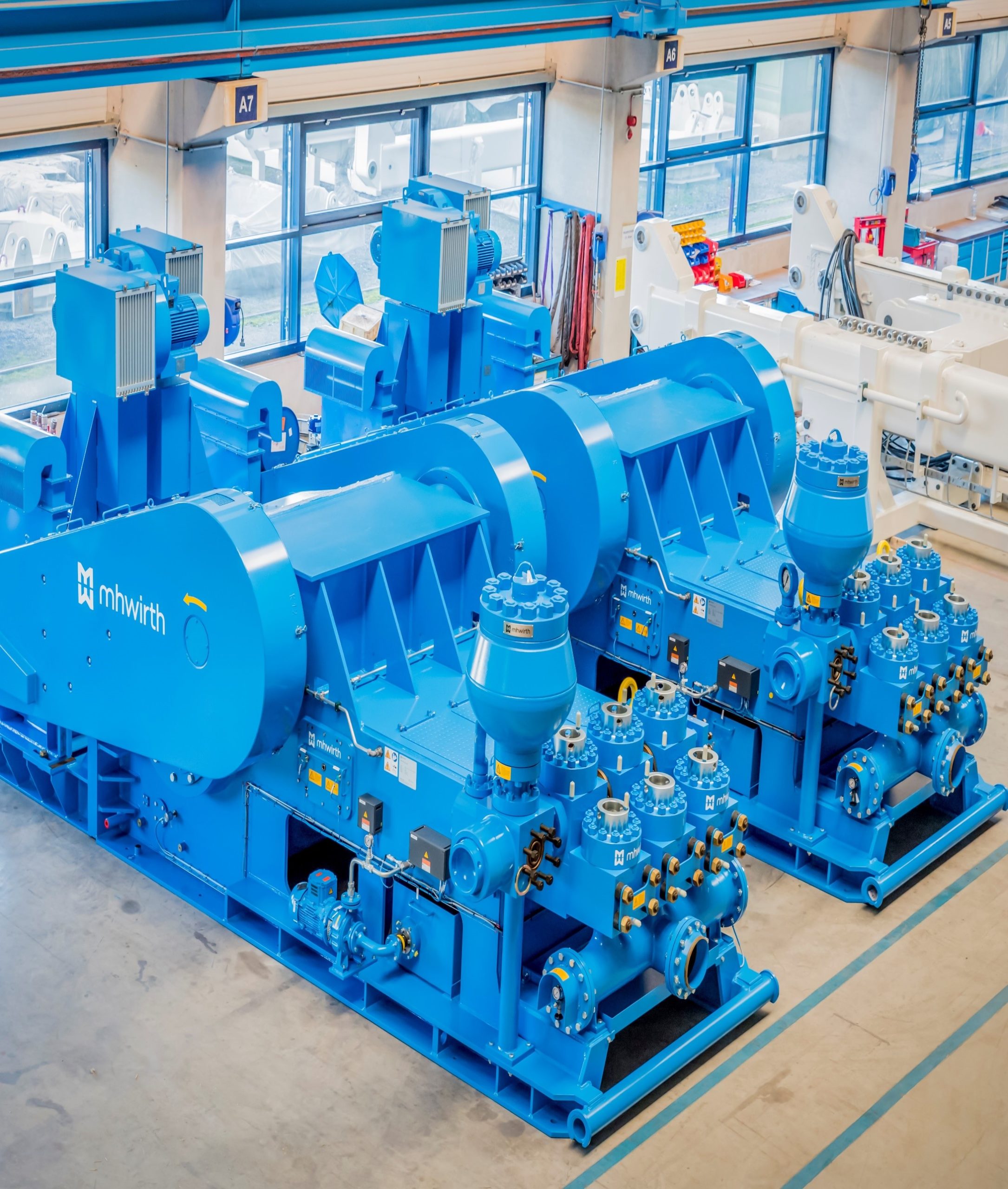
With a large variety of drives, motor and skid configurations, HMH provides a mud pump solution for any project and drilling requirement. We deliver high pressure triplex mud pumps with a maximum discharge pressure between 5 000 and 10 000 psi and power ratings between 1 000 and 2 200 hp.
Our mud pumps reduce service costs and increase operational efficiency. Our unique gear driven drive has an extended lifetime of up to 50 000 hours and is more durable than traditional chain or belt driven drives. Our hydraulic quick release system allows fast and safe replacement of fluid end parts.
The 1600 hp mud pumps are designed to circulate drilling fluid under high pressure (up to 7 500 psi) down the drill string to support any project requirements.
The 2200 hp mud pumps are designed for circulating drilling fluid under high pressure (up to 10 000 psi) down the drill string to support especially deep drilling operations.

+49 / (0)2431 / 830, Telefax +49 / (0)2431 / 83267 Web. http://www.wirth-europe.com, E-mail: info@wirth-europe.com HP Mud Pump TPK 7 1/2" x 14" / 2200 7500 PSI
Operation / Maintenance / Spare Parts Volume I Serial-No.: 158 - 160 OT OPERATE THE MAORE READING© WIRTH Maschinen- und Bohrgeräte-Fabrik GmbH - Änderungen vorbehalten / Subject to modifications
OT OPERATE THE MACHIE EACH PERSON CHARGED WITH OPERATION, ASSEMBLY, MAINTENANCE AND REPAIR OF THE MUD PUMP MUST HAVE READ THIS MANUAL AND UNDERSTOOD IT AND ADHERE TO ITS CONTENTS. ! WE DO NOT ASSUME ANY RESPONSIBILITY FOR INJURY, DAMAGE AND OPERATIONAL TROUBLES RESULTING FROM THE NON-ADHERENCE TO THE MANUAL.
Maschinen- und Bohrgeräte-Fabrik GmbH Kölner Straße 71-73, D-41812 Erkelenz Tel. +49 / (0)2431 / 830 Telefax +49 / (0)2431 / 83267 Web. http://www.wirth-europe.com E-mail: info@wirth-europe.com
Front sheet-E_R0.doc Rev.0 I / III © WIRTH Maschinen- und Bohrgeräte-Fabrik GmbH - Änderungen vorbehalten / Subject to modifications
No part of this publication may be reproduced, stored in a retrieval system or transmitted in any form or by any means without prior writtenpermission from WIRTHIn pursuing a policy of constant product development and update, WIRTH reserves the right to make changes at any time and withoutundertaking to give prior notice; therefore, also this publication may be subject to changes.
ATTENTION This safety notice denotes a hazard exists. This warning is used wherever inadequate observance or non-observance of operation instructions, specified operating sequences, etc. may result in damage to the pump or other equipment and/or reduce the safety standards for which the pump has been designed..© WIRTH Maschinen- und Bohrgeräte-Fabrik GmbH - Änderungen vorbehalten / Subject to modifications
NOTE This safety notice draws the attention to important technical and/or technological information that allows using the machine in a more efficient way. They also direct the reader’s attention to all those operations for which WIRTH International After-Sales service must be contacted -i.e. when needing ORIGINAL SPARE PARTS or TECHNICAL ASSISTANCE INTERVENTIONS.
In the handbook, the message following the signal words may be either written or illustrated. Special labels or warning plates are also applied on the machine. They provide instructions on how to identify the hazards which, if under-estimated, may result in serious injury or death. The manufacturer WIRTH cannot foresee all possible circumstances which may result in hazardous situations when using and operating the machine. For this reason, the safety notices, contained in this manual or applied on the machine, cannot include all possible situations of potential danger. When, during work, you follow procedures, equipment or methods other than those expressly recommended by WIRTH, it is of the utmost importance that you do your job taking into account the safety limits for your own as well as for everybody else’s safety. Additionally, you must be sure that the machine does not suffer from damage or become unsafe due to operation, lubrication, maintenance or repair works you decide to carry out.
WIRTH-Project-No.: ............................. P.000531 Serial-No.: ............................................. 158 - 160
TPK\TPK 2200\SN-158-160\1-00-E_R0.doc TPK 7 ½“ x 14“ / 2200 - SN 158-160 Rev. 00 1 / 15 CONTENTS
VOLUME I VOLUME II(OPERATION / MAINTENANCE / SPARE (SUB VENDORS)PARTS)Front sheet Front sheetContents (Page 1 - 15) Contents (Page 12 - 15)Manufacturer`s Declaration 1. Proximity switch (IFM)Section I (Operation / Maintenance) 2. Ventilation filter (EPE) 3. Filter (EPE)1. Introduction 4. Centrifugal pump (Baker Hughes)2. Safety Information 5. Coupling (Flender)3. Brief Description 6. E-Motor (Siemens)4. Technical Data 7. Flow sensor (IFM)5. Function & Operation 8. Gear Pump Lubrication (Kracht)6. Motor Starting & System 9. Filter (EPE) Prerequisite 10. Heating Element (Schniewindt)7. Lifting & Installation Instructions 11. Pressure relief valve (Kracht)8. Maintenance 12. Heat Exchanger (UH)9. Preservation & Storage Procedure 13. Medium pressure filter (Pall)10. Cleaning & Disposal 14. Flow switch (Honsberg) 15. Temperature transmitter (Labom)Section II (Spare Parts) 16. Roller chain (Rexnord) 17. Main motor (Breuer)1. Order example – spare parts 18. Heating Element (Schniewindt)2. Pump unit, complete 19. Manometer (Oteco)3. Power End 20. Pulsation dampener (Mattco)4. Liner Cooling 21. Safety relief valve (Retsco)5. Lubrication System 22. Hand Trolleys (Yale)6. Fluid End 23. Spur wheel flange course (Yale)7. Chain drive 24. Hand lever pump (Schaaf)8. Pressure gauge9. Pressure Manifold / Safety Valve10. Jib crane11. ----12. Accessories13. Consumables
TPK\TPK 2200\SN-158-160\1-00-E_R0.doc TPK 7 ½“ x 14“ / 2200 - SN 158-160 Rev. 00 2 / 15 CONTENTS
3. BRIEF DISCRIPTION ............................................................................ (Rev. 01) 1. General ...........................................................................3 2. Pump Unit .......................................................................3 3. Power End ......................................................................3 4. Fluid End / Valves ...........................................................4 5. Pressure manifold / Pulsation Dampener........................4 6. Suction Manifold..............................................................4 7. Chain Lubrication ............................................................4 8. Gear Lubrication .............................................................4 9. Liner Cooling ...................................................................4 10. Pre-charging pump (not scope of WIRTH)......................5 (Pumpe/TPK/Beschr/1-03-E_R1 Brief description –.doc)
TPK\TPK 2200\SN-158-160\1-00-E_R0.doc TPK 7 ½“ x 14“ / 2200 - SN 158-160 Rev. 00 3 / 15 CONTENTS
4. TECHNICAL DATA / GENERAL ARRANGEMENT ............................ (Rev. 00) 1. Total weight / overall dimensions .................................3 2. Performance data.........................................................3 3. Operation range ...........................................................3 4. Main drive.....................................................................3 4.1 Drive motor...................................................................3 4.2 Cooling blower .............................................................3 4.3 Motor heater.................................................................3 5. Lubrication Gear-box....................................................4 5.1 Drive motor...................................................................4 5.1.1 Motor heater.................................................................4 5.2 Pump............................................................................4 5,3 Heat Exchanger ...........................................................4 5.4 Heating Element...........................................................4 5.5 Temperature transmitter...............................................5 6. Lubrication Chain drive ................................................5 6.1 Drive motor...................................................................5 6.1.1 Motor heater.................................................................5 6.2 Pump............................................................................5 6.3 Heat Exchanger ...........................................................5 6.4 Heating Element...........................................................6 6.5 Temperature transmitter...............................................6 7. Liner Cooling ................................................................6 7.1 Drive motor...................................................................6 7.1.1 Motor heater.................................................................6 7.2 Centrifugal pump..........................................................6 7.3 Flow switch Sensor ......................................................7 7.4 Flow switch control unit ................................................7 8 Stroke monitoring .........................................................7 8.1 Proximity switch ...........................................................7 (Pumpe\TPK\TPK2200\Beschr\1-04-E_R0-Techn Data SN 158-160.doc)
TPK\TPK 2200\SN-158-160\1-00-E_R0.doc TPK 7 ½“ x 14“ / 2200 - SN 158-160 Rev. 00 4 / 15 CONTENTS
5. FUNCTIONAL DESCRIPTION .............................................................. (Rev. 02) 1. General ......................................................................3 2. Safety instructions......................................................4 3. Start-up ......................................................................5 3.1 Motor control ..............................................................5 3.2 General visual check..................................................5 3.3 Pre-operational checks of pump ................................6 3.4 Checks – requirements – oil and water......................6 4. Functioning description ..............................................7 4.1 Power end..................................................................7 4.1.1 Power end (belt drive)................................................7 4.1.2 Power end (chain drive) .............................................8 4.2 Gear drive .................................................................10 4.3 Fluid end ....................................................................12 4.4 Hydraulic system for stud tensioning .........................14 4.5 Liner assembly...........................................................16 4.6 Liner and piston rod assembly ...................................17 4.7 Pressure manifold ......................................................18 4.8 Lubrication system .....................................................20 4.9 Liner cooling system ..................................................25 4.10 Pre-charging ..............................................................26 4.11 Determination of pre-charging pressure of pulsation dampener ...................................................27 4.11.1 Pre-charging of pulsation dampeners ........................28 (Pumpe\TPK\Beschr\1-05-E_R2 Function.doc)
6. MOTOR STARTING & SYSTEM PREREQUISITE ............................... (Rev. 00) 1. General description....................................................3 1.1 Drive main motors of mud pumps ..............................3 1.2 Secondary drives and measuring instruments of mud pumps ............................................................4 1.3 Starting sequence ......................................................5 1.4 Cut-out sequence.......................................................6 1.5 Gear lubrication..........................................................6 1.6 Chain Lubrication .......................................................7 1.7 Liner cooling...............................................................8 1.8 Stroke meter ..............................................................9 1.9 Pre-charging pump (by third party) ............................9 2. Trouble shooting charts .............................................10 2.1 Main drive / blower cooling ........................................10 2.2 Gear lubrication..........................................................10 2.3 Chain Lubrication .......................................................11 2.4 Liner cooling...............................................................12 (Pumpe\TPK\TPK2200\Beschr\1-06-E_R0-Motorstart SN 158-160.doc)
TPK\TPK 2200\SN-158-160\1-00-E_R0.doc TPK 7 ½“ x 14“ / 2200 - SN 158-160 Rev. 00 5 / 15 CONTENTS
8. MAINTENANCE ..................................................................................... (Rev. 03) 1. General ...................................................................3 2. Safety......................................................................4 3. Maintenance intervals .............................................7 4. Welding...................................................................7 5. Notes to Maintenance Manual ................................8 6. Operations before / during / after maintenance ......8 7. Hydraulic hoses and hose lines ..............................11 8. Lubricants / oils.......................................................12 9. Torque and tensioning setting values .....................14 9.1 Screw tightening torque (Nm) .................................14 9.2 Pressure values for hydraulic tools .........................14 10. Maintenance ...........................................................15 10.1 Removal and installation of valve closures .............16 10.1.1 Removal..................................................................16 10.1.2 Installation...............................................................17 10.2 Removal and installation of valve seats..................18 10.2.1 Removal..................................................................18 10.2.2 Installation...............................................................19 10.3 Turning of mud pump by hand ................................20 10.4 Removal and installation of pistons & piston rods ..22 10.4.1 Removal..................................................................22 10.4.2 Installation...............................................................23 10.5 Removal and installation of liners ...........................24 10.5.1 Removal..................................................................24 10.5.2 Installation...............................................................25 10.6 Removal and installation of pressure connection ...26 10.6.1 Removal..................................................................26 10.6.2 Installation...............................................................26 10.7 Drive mode .............................................................27 10.7.1 Belt drive.................................................................27 10.7.2 Chain drive..............................................................27 11. Repair of mud pump ...............................................28 12 Quality analyses of the lubrication oil .....................29 13. Maintenance chart with execution remark ..............30 14. Trouble shooting chart ............................................36 (Pumpe\TPK\Beschr\1-08-E_R3 Maintenance.doc)
Annex: Filling Materials ..........................................................................1/1 - 00 (Pumpe\TPK\TPK2200\Beschr\overview-chain drive-E_R0.doc)
Maintenance Scheme ................................................................1/3 - 02 (Pumpe\TPK\Beschr\maintenance scheme-chain drive-E_R02.doc)
TPK\TPK 2200\SN-158-160\1-00-E_R0.doc TPK 7 ½“ x 14“ / 2200 - SN 158-160 Rev. 00 6 / 15 CONTENTS
TPK\TPK 2200\SN-158-160\1-00-E_R0.doc TPK 7 ½“ x 14“ / 2200 - SN 158-160 Rev. 00 7 / 15 CONTENTS
Example for Ordering ................................................... - / page 1/1 -0 (Order Wirth-E_R0) FAX form ..................................................................... - / page 1/2 -0 (Fax Wirth-E_R0)
2. PUMP UNIT COMPLETE • Pump unit complete.................................................B0044194 - 01 / 11060876 - 1
TPK\TPK 2200\SN-158-160\1-00-E_R0.doc TPK 7 ½“ x 14“ / 2200 - SN 158-160 Rev. 00 8 / 15 CONTENTS
4. LINER COOLING Liner cooling.................................................................B0025603 - 05 / 11041952 - 5 [B0044194 – 03] - 18 - Filter S280 (#21006515) ...................................................... see Volume II -- EPE - 26 - Centrifugal pump 1“x1 ½“ C-11 (#21039338) ...................... see Volume II -- Baker Hughes - 30 - Coupling N-EUPEX Typ B95 (#20227501) .......................... see Volume II -- Flender - 32 - E-Motor 1LA 6107 (#21043860) .......................................... see Volume II -- Siemens - 47 - Flow sensor SF5200 (21029555)........................................ see Volume II -- IFM
5. LUBRICATION SYSTEM Lubrication System.......................................................B0041823 - 01 / 11058473 - 1 [B0044194 – 04] - 02 - E-Motor 1LA 6133 (#21043861) .......................................... see Volume II -- Siemens - 03 - Gear pump KF 63 RF 1 (#2137600) .................................... see Volume II -- Kracht - 13 - Filter SE 225 (#21002093) .................................................. see Volume II -- EPE - 25 - Heating Element 93/F57-Ex2,0 (#21043863) ...................... see Volume II -- Schniewindt - 32 - Pressure relief valve SPVF (#21018076) ............................ see Volume II -- Kracht - 33 - Heat exchanger (#21036446) .............................................. see Volume II -- UH - 42 - Medium pressure Filter (#21020268)................................... see Volume II -- Pall - 52 - Flow switch (#21005342)..................................................... see Volume II -- Honsberg - 74 - Temperature transmitter (21031968)................................... see Volume II -- Labom
TPK\TPK 2200\SN-158-160\1-00-E_R0.doc TPK 7 ½“ x 14“ / 2200 - SN 158-160 Rev. 00 9 / 15 CONTENTS
7. CHAIN DRIVE Chain drive with lubrication .........................................B0042017 - 00 / 11058621 - 0 [B0044194 – 06] - 02 - Ventilation filter TLF II 4-50 (#20234093) ............................ see Volume II -- EPE - 15 - Roller chain 24A-6 (#21028341).......................................... see Volume II -- Rexnord - 41 - E-Motor AFI 400 M623 (#21043899) ................................... see Volume II -- Breuer - 42 - E-Motor AFI 400 M623 (#21043898) ................................... see Volume II -- Breuer - 59 - E-Motor1 LA 6133 (#21043861) .......................................... see Volume II -- Siemens - 63 - Gear pump KF 63 RF 1 (#21037600) ................................... see Volume II -- Kracht - 73 - Flow switch (#21005342 ...................................................... see Volume II -- Honsberg - 84 - Heat exchanger (#21036446) ............................................... see Volume II -- UH - 87 - Temperature transmitter (#21031968) ................................. see Volume II -- Labom - 97 - Heating Element 93/F57-Ex 0,89 (#21043857) ................... see Volume II -- Schniewindt
TPK\TPK 2200\SN-158-160\1-00-E_R0.doc TPK 7 ½“ x 14“ / 2200 - SN 158-160 Rev. 00 10 / 15 CONTENTS
12. ACCESSORIES Tools ................................................................ - / 11043496 - 0 • Hydr. hand lever pump compl..................................A2305573 - 01 / 10234283 - 1 - 02 - Hand lever pump HP 1800-2S-1 (#20234284)..................... see Volume II -- Schaaf • Plug-in coupling G ¾“ – 3000 bar ....................... A2302491 - xx / 10267730 - 0 • Assembly for fluid end tensioning............................A2102163 - 01 / 11002814 - 1 • Stud tensioner SSV M 48 ..................................A2202675 - 01 / 10234288 - 1 • Liner puller ......................................................A2305502 - xx / 10234300 - 0 • Charging hose for suction dampener .....................A2203497 - xx / 10234311 - 0 • Wear ring pulling device .........................................A2306184 - xx / 11004045 - 0 • Piston mounting tool ................................................B0008148 - 01 / 11019861 - 1 • Chain tensioner ......................................................A2305826 - xx / 11030324 - 0
[..........] ==> Drawing - Pos. (# ......) ==> Order-no. WIRTH Maschinen- und Bohrgeräte-Fabrik GmbH, Postfach 1655/1660, D-41806 Erkelenz Tel. 02431/830 - Telefax 02431/83267
TPK\TPK 2200\SN-158-160\1-00-E_R0.doc TPK 7 ½“ x 14“ / 2200 - SN 158-160 Rev. 00 11 / 15 CONTENTS
(# ......) ==> Order-no. WIRTH Maschinen- und Bohrgeräte-Fabrik GmbH, Postfach 1655/1660, D-41806 Erkelenz Tel. 02431/830 - Telefax 02431/83267
TPK\TPK 2200\SN-158-160\1-00-E_R0.doc TPK 7 ½“ x 14“ / 2200 - SN 158-160 Rev. 00 12 / 15 CONTENTS
(# ......) ==> Order-no. WIRTH Maschinen- und Bohrgeräte-Fabrik GmbH, Postfach 1655/1660, D-41806 Erkelenz Tel. 02431/830 - Telefax 02431/83267
TPK\TPK 2200\SN-158-160\1-00-E_R0.doc TPK 7 ½“ x 14“ / 2200 - SN 158-160 Rev. 00 13 / 15 CONTENTS
TPK\TPK 2200\SN-158-160\1-00-E_R0.doc TPK 7 ½“ x 14“ / 2200 - SN 158-160 Rev. 00 14 / 15 CONTENTS
(# ......) ==> Order-no. WIRTH Maschinen- und Bohrgeräte-Fabrik GmbH, Postfach 1655/1660, D-41806 Erkelenz Tel. 02431/830 - Telefax 02431/83267
TPK\TPK 2200\SN-158-160\1-00-E_R0.doc TPK 7 ½“ x 14“ / 2200 - SN 158-160 Rev. 00 15 / 15 HP Mud Pump TPK 7 1/2" x 14" / 2200 7500 PSI© WIRTH Maschinen- und Bohrgeräte-Fabrik GmbH - Änderungen vorbehalten / Subject to modifications
Front sheet-Manufacturer`s Declaration-E_R0.doc Rev.0 I/I WIRTH Maschinen- und Bohrgeräte-Fabrik GmbH Kölner Straße 71-73 41812 ERKELENZ. GERMANY Telefon +49-2431 83-0 Telefax +49-2431 83-267 Internet: http://www.wirth-europe.com e-mail : info@wirth-europe.com
Type : TPK 7 %" x 14"/2200 Serial-no. : 158 Year of fabrication : 2008 WIRTH-project-no.: P.000531
The EC-Manufacturer"s Declaration is only valid, when theTriplex Piston Pump is used in accordance with regulations and according to the operation and maintenance instructions.
Commissioning shall not commence until it has been ascertained that the electric supply and pump control systems, which form part of the Triplex Piston Pump installation, corresponds to the regulations of the above mentioned EC guidelines for machines.
Directors: Christoph Kleuters - Wilfried Kroppen - Bj0rn Klepsvik - Trond RobstadP.531-NO.158 Chairman of the Supervisory Board: Mads Andersen Registered Office: Erkelenz . Amtsgericht Mönchengladbach HRB 8471 WIRTH Maschinen- und Bohrgeräte-Fabrik GmbH Kölner Straße 71-73 41812 ERKELENZ. GERMANY Telefon +49-2431 83-0 Telefax +49-2431 83-267 Internet: http://www.wirth-europe.com e-mail : info@wirth-europe.com
Type: TPK 7 %" x 14"/2200 Serial-no. : 159 Year of fabrication: 2008 WIRTH-project-no.: P.000531
The EC-Manufacturer"s Declaration is only valid, when the Triplex Piston Pump is used in accordance with regulations and according to the operation and maintenance instructions.
Cornmissioning shall not commence until it has been ascertained that the electric . supply and pump control systems, which form part of the Triplex Piston Pump installation, corresponds to the regulations of the above mentioned EC guidelines for machines.
P . 5 3 ·..r~ o .15 9 Chairman of the Supervisory Board: Mads Andersen . Registered Office: Erkelenz. . Amtsgericht Mönchengladbach HRB 8471l- -- _ ._ - - - _ ._- _._- _._ ----- - -- - ------ - - WIRTH Maschinen- und Bohrgeräte-Fabrik GmbH Körner Straße 71-73 41812 ERKELENZ. GERMANY Telefon +49-2431 83-0 Telefax +49-2431 83-267 Internet: http://www.wirth-europe.com e-mail: info@wirth-europe.com
The EC-Manufacturer"s Declaration is only valid, when the Triplex Piston Pump is used in accordance with regulations and according to the operation and maintenance instructions.
Commissioning shall not commence until it has been ascertained that the electric supply and pump control systems, which form part of the Triplex Piston Pump installation, corresponds to the regulations of the above mentioned EC guidelines for machines.
@ DIN ENISO 9001 Reg. No. 133 Directors : Christoph Kleuters - Wilfr ied Kreppen - Bj0rn Klepsvi k - Trond Robst adP.531-No.160 Chairman of the Supervisory Board: Mads Andersen Registered Office: Erkelenz . Amtsgericht Mönchengladbach HRB 8471 - - - - - - - - - - - - - - - - - HP Mud Pump TPK 7 1/2" x 14" / 2200 7500 PSI© WIRTH Maschinen- und Bohrgeräte-Fabrik GmbH - Änderungen vorbehalten / Subject to modifications
1. General ................................................................................................3 2. Manufacturer`s Identification ..............................................................5 3. Liability.................................................................................................5 4. Safety Equipment / Explanations of Symbols and Special Notes........6 5. After-Sales Service / Spare Parts Supply............................................7 6. Safety and Information Signs ..............................................................7 7. Use in Accordance with the Purpose...................................................7 8. Expert Examination .............................................................................7© WIRTH International - Subject to modifications
This document, including all pictures and drawings are copywrited and any reproduction without written authorization from the manufacturer is strictly prohibited.© WIRTH International - Subject to modifications
At all times, operators must be familiar with and follow all applicable safety regulations and standardsof good practice. © WIRTH International - Subject to modifications
which arise due to unauthorized modifications or non-compliance of the manufacturer’s recommendations or which can be derived there from, when using accessories/spare parts, which were not recommended or supplied by the© WIRTH International - Subject to modifications
NOTEThis safety notice draws the attention to important technical and/or technological informationthat allows using the machine in a more efficient way. They also direct the reader’s attentionto all those operations for which WIRTH International After-Sales service must be contacted -i.e. when needing ORIGINAL SPARE PARTS or TECHNICAL ASSISTANCE INTERVENTIONS.
Complying with these notes and warnings does not relieve you of your responsibility to work safely and observe all applicable safety laws and regulations. © WIRTH International - Subject to modifications
The manufacturer WIRTH International cannot foresee all possible circumstances which may resultin hazardous situations when using and operating the machine. For this reason, the safety notices,contained in this manual or applied on the machine, cannot include all possible situations of potentialdanger.When, during work, you follow procedures, equipment or methods other than those expresslyrecommended by WIRTH International , it is of the utmost importance that you do your job takinginto account your own safety as well as the safety of other workers.
Machinery, instruments and equipment should be checked by an expert at least once per year, before they are put into operationand after constructional modifications are made. Expert is who, due to his professional training and experience has sufficient knowledge in the field of© WIRTH International - Subject to modifications
1. General ............................................................................ 3 2. Operating Company’s Obligations.................................... 4 3. Responsibilities of the Personnel ..................................... 4 4. Employment Restrictions ................................................. 4 5. Machine Operation........................................................... 5 6. Safety Devices ................................................................. 5 7. Explanation of Symbols and Information Signs ................ 6 8. Prior / While / After Working............................................. 7 9. Personal Protection Equipment........................................ 8 10. Assembly / Transport ....................................................... 8 11. Maintenance / Cleaning ................................................... 9 12. Hand Signals.................................................................... 9© WIRTH International - Subject to modifications
Revisions Index: Rev. Date Prepared by 01 18.04.07 KHS WIRTH Maschinen- und Bohrgeräte-Fabrik GmbH, Postfach 1655/1660, D-41806 Erkelenz Tel. 02431/830 - Telefax 02431/83267
Allg-Beschr\1-02-E_R1 Safety.doc Rev. 1 1 / 11 Safety© WIRTH International - Subject to modifications
Any modification carried out of the original unit design without WIRTH’s prior consent will be considered unauthorized. The exclusive use of original WIRTH spare parts or purchased parts being in accordance with the original design, respectively, is also part of this requirement.
Failure to read and follow the instructions in this manual may greatly increase the risk of personal injury (including death) and/or damage to equipment.© WIRTH International - Subject to modifications
When being actuated they shall initiate the immediate standstill of the main drives. Safety devices of moving unit parts may be opened or removed only when the driving system has been stopped or protected against unauthorized starting. Operating company’s lockout/tagout procedure must be followed to ensure all energy is locked out and released prior to working on the unit.© WIRTH International - Subject to modifications
This safety notice draws the attention to important technical and/or technological information that allows using the machine in a more efficient way. They also direct the reader’s attention to all those operations for which Wirth After-Sales service must be contacted -i.e. when needing ORIGINAL SPARE PARTS or TECHNICAL ASSISTANCE INTERVENTIONS.© WIRTH International - Subject to modifications
8. Prior / While / After Working Do not smoke or use exposed flame while refuelling oil. Do not store flammable fluids near ignition sources. Keep unit free of dirt and lubricants. Do not store oily cloths as they might ignite suddenly. Always keep first-aid kit and fire extinguisher readily available. Keep emergency numbers for doctor, ambulance, hospital, and fire brigade near the telephone. Start driving engine only when all work at the unit has been terminated. Set all operation elements in neutral or zero position, respectively. Ensure that all safety devices are functioning. Ensure that all screws and bolts remain secured. Switch off driving engine in case of problem or danger using mushroom push button „EMERGENCY STOP“. Ensure during operation that hydraulic hoses and electric lines are in good condition and not bent. Warn persons against standing near-by by giving an alarm prior to starting the driving engine. Provide adequate lighting. Do not exceed permissible loads (see Technical Data). Determine weight prior to lifting any loads. In case of flashing warning lights stop working at once. Trace the fault and eliminate it prior to restarting the unit. Clean tools only while out of operation. Do not reach into tools during operation. It is forbidden to stay in the dangerous area of the unit. Always ensure having a three-point contact with steps and handle and keep watching the unit when getting on/off the unit. Never use control elements as climbing aid. Do not jump on or off the unit. Watch out for slippery platforms, steps, or handrails. Only use proper climbing, walking and working surfaces and keep them in a reliable condition.© WIRTH International - Subject to modifications
10. Assembly / Transport Assembly and transport personnel must have the required professional knowledge. Tools, hoists, attachment means, sub-trestles, and other aids must be of sufficient capacity and in a condition safe to work with. Protect unit and equipment against unintentional and unauthorized starting. Put the equipment on the ground in such a way as to exclude any movements between mechanical and hydraulic connections. De-pressurize hydraulic system. Secure equipment and components being added or removed with suitable attachment means. Attach components to the corresponding eyes or fixtures only. While jacking-up, the gravity center shifts. The unit must be secured against toppling over. Secure loose parts against falling. Do not carry out any welding, flame cutting, machining, or other modifications at assemblies subject to static load without having been given WIRTH’s express approval in writing.© WIRTH International - Subject to modifications
Pressure control and safety valves to be adjusted by WIRTH service fitters only or fitters having been authorized by WIRTH to do so.
Slowly Stretch right arm horizontally, palm points ahead, moving arm up and down© WIRTH International - Subject to modifications
Indicate reduction of a Keep both palms in parallel distance and put them together in accordance with the distance© WIRTH International - Subject to modifications
1. General ............................................................................ 3 2. Pump Unit ........................................................................ 3 3. Power End........................................................................ 3 4. Fluid End / Valves ............................................................ 4 5. Pressure Manifold / Pulsation Dampener ......................... 4 6. Suction Manifold............................................................... 4 7. Chain Lubrication ............................................................. 4 8. Gear Lubrication............................................................... 4 9. Liner Cooling .................................................................... 5 10. Pre-charging Pump .......................................................... 5 und Maschinen- Bohrgeräte-Fabrik und GmbH Bohrgeräte-Fabrik - Änderungen GmbH vorbehalten - Änderungen / Subject vorbehalten to modifications to modifications / Subject
Rev. Date Prepared by 00 17.08.07 KHW © WIRTH© WIRTH
Pumpen\TPK\Beschr\1-03-E_R1 Brief description – chain drive.doc Rev. 1 1/5 Brief description© WIRTH Maschinen- und Bohrgeräte-Fabrik GmbH - Änderungen vorbehalten / Subject to modifications
Blank page WIRTH Maschinen- und Bohrgeräte-Fabrik GmbH, Postfach 1655/1660, D-41806 Erkelenz Tel. 02431/830 - Telefax 02431/83267
2/5 Rev. 1 Pumpen\TPK\Beschr\1-03-E_R1 Brief description – chain drive.doc Brief description
1. General WIRTH triplex piston pumps (TPK) are single-acting pumps. They are provided with the well-proven and patented WIRTH hydraulic systems. Besides a high-degree operational safety they allow the easy and quick installation and removal of the wear parts. Configuration of the triplex pumps – especially those of the fluid ends – considers the best accessibility and inspection possibilities. Each pumps has been subject to a test run in the manufacturer’s works and can directly be operated on the drilling platform to its full efficiency.
A detailed description of the pump as well as its maintenance and installation instructions are contents of the separate instructions.
BEFORE STARTING ANY OPERATION, THOROUGHLY READ THE FOLLOWING CHAPTERS AND ADHERE TO THE PRESCIPTIONS GIVEN IN THE ENTIRE PUMP MANUAL.
2. Pump Unit The pump is mounted on a base skid, completely with its 1 or 2 drive main motors and all secondary equipment. to modifications
Delivery volume of the pump is proportional to its number of strokes. The performance data chart (see to modifications
The pump is driven


 8613371530291