
mud pump discharge formula supplier

Distributor of engineered fluid handling pumps, packaged pumping systems, repairs, parts, & integrated pump control systems. Mud pumps, chiller/condenser pumps, plumbing pumps, boiler feed systems, in-line circulators, condensate systems, sump & sewage pumps, end suction pumps, submersible sump & sewage, non-clogs & grinders, self primers, packaged lift stations, variable speed pump systems, metering pumps, chemical injection systems, chemical mixing systems, peristaltic pumps for chemical feed, high viscous & shear sensitive fluids, self primers, stainless steel, trash pumps, hot oil pumps, vertical turbine pumps, sanitary pumps, marine pumps, industrial pumps, ANSI end suction, vertical cantilever, double suction, non-clogs, progressive cavity pumps, helical gear pumps, well pumps, lab pumps, hose pumps, control valves, check valves, air release valves, tanks, pressure vessels.

Rig pump output, normally in volume per stroke, of mud pumps on the rig is one of important figures that we really need to know because we will use pump out put figures to calculate many parameters such as bottom up strokes, wash out depth, tracking drilling fluid, etc. In this post, you will learn how to calculate pump out put for triplex pump and duplex pump in bothOilfield and Metric Unit.

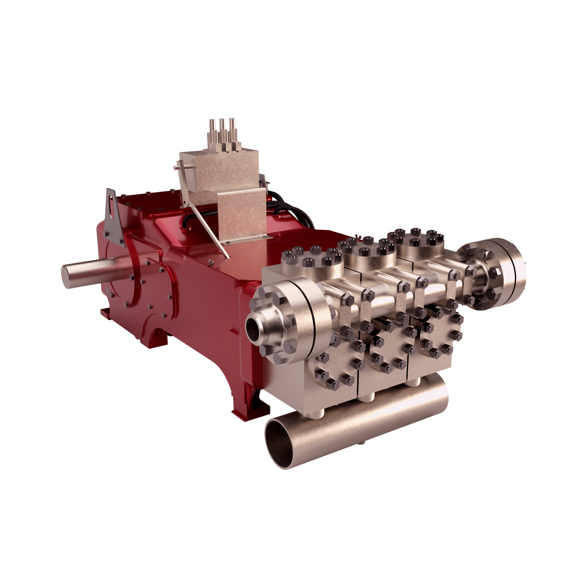
The NOV 12-P-160 Mud Pumps includes (3) Three New National 12-P-160 Triplex Mud Pumps 1600 HP, 7-1/4″ bore x 12″ stroke, single acting. 5000 PSI fluid ends. 1600 HP Bare Mud Pumps are currently configured for Offshore Service. The NOV 12-P-160 Mud Pumps are located in Houston and ready to be unitized for service.
Forged Steel crankshaft, Individual forged steel two piece interchangeable standard modules, 6-1/2” mission fluid king liners, Standard polyurethane valves and seats, Two piece fast change piston rods, Supreme pistons, Metal to metal liner retention, Clamp type liner and piston rod connections, Fast change valve covers standard, Piston liner lubricant spray system, Liner spray pump, Power end lube system with filter. Mounted on Integral two runner skid, Suction Manifold with vertical suction stabilizer, Suction line pressure relief valve, set for 70 PSI
Includes: motor supports, motor frame, tensioning screws, 2 V-belt guards, 2 pump Sheaves, 2 motor sheaves, banded V-belts, Holes to be drilled to accept EDM D79 Or GE-752 Traction Motors
National Oilwell Varco (NOV) is an American multinational corporation based in Houston, Texas. It is a leading worldwide provider of equipment and components used in oil and gas drilling and production operations, oilfield services, and supply chain integration services to the upstream oil and gas industry. The company conducts operations in more than 600 locations across six continents, operating through three reporting segments: Rig Technologies, Wellbore Technologies, and Completion & Production Solutions. National Oilwell’s two main predecessors, Oilwell Supply and National Supply, were founded in 1862 and 1893, respectively. These two companies manufactured and distributed pumps and derricks.
abide by the contract", conforms towards the market requirement, joins during the market competition by its good quality likewise as provides additional comprehensive and great services for customers to let them turn out to be big winner. The pursue of your enterprise, is the clients" fulfillment for Mud Pump Discharge Formula, , , , We hope to establish additional organization interactions with prospects all over the entire world.

Since the NOV A1700-PT Triplex Mud Pump was built approximately 60 years ago, the industry has widely accepted the three cylinder or triplex style pump. Triplex mud pumps are manufactured worldwide, and many companies have emulated the original design and developed an improved form of the triplex pump in the past decade.
NOV A1700-PT Triplex Mud Pumps have many advantages they weight 30% less than a duplex of equal horsepower or kilowatts. The lighter weight parts are easier to handle and therefore easier to maintain. The other advantages include;They cost less to operate
One of the more important advantages of triplex over duplex pumps, is that they can move large volumes of mud at the higher pressure is required for modern deep hole drilling.
NOV A1700-PT Triplex Mud Pump is gradually phasing out duplex units. In a triplex pump, the pistons discharge mud only when they move forward in the liner. Then, when they moved back they draw in mud on the same side of the piston. Because of this, they are also called “single acting.” Single acting triplex pumps, pump mud at a relatively high speeds. NOV A1700-PT Triplex Mud Pump has three pistons each moving in its own liner. It also has three intake valves and three discharge valves. It also has a pulsation dampener in the discharge line.

In addition to selecting the proper suction pipe diameter and having adequate NPSHA, the submergence level and suction pipe configuration must be considered. Submergence level is the depth of the suction pipe inlet below the liquid surface. If an inadequate submergence level exists, an air vortex will form that extends from the liquid surface to the inlet of the suction pipe. This will introduce air into the system, resulting in either turbulent flow patterns or vapor locking of the pump. Amount of submergence required varies with velocity of the fluid. Fluid velocity is controlled by flow rate and pipe diameter. Refer to Figure 1. to determine submergence required based on fluid velocity (fluid velocity can be found in Friction Loss (Centrifugal Pumps Velocity Measured), in the column ‘‘V (ft/sec)’’).
If a system utilizes a 6-inch suction line with a flow rate of 600 gpm, suction-line velocities will be 6.6 fps and the line will therefore require approximately 3.5 feet of liquid surface above the suction-line entrance. Once the submergence level drops below 3.5 feet, an air vortex will form, causing air to enter the pump suction, resulting in a turbulent flow pattern and/or vapor lock.
In addition to proper line size and submergence level, a suction pipe should slope gradually upward from the source to the pump suction. This prevents air traps within the suction line. There should be a straight run prior to the pump entrance of at least two pipe diameters in length to reduce turbulence. A smooth-flowing valve should be installed in the suction line that will allow the pump to be isolated for maintenance and inspection. If a suction hose is used in lieu of hard piping, the hose must be noncollapsing. Refer to Figures 3 and 4 for examples of accepted piping practices.
Triplex mud pumps are often operated at speeds at which head in the suction tank is insufficient to maintain fluid against the piston face during the filling stroke. If fluid does not remain against the face, air is sucked in from behind the piston, causing a fluid void. If a void is formed, the piston strikes the fluid when the piston reverses direction during the pressure stroke. This causes a shock load that damages the triplex power end and fluid end and lowers expendable parts life. Supercharging pumps are used to accelerate fluid in the suction line of a triplex mud pump during the filling stroke, allowing fluid to maintain pace with the piston. A properly sized supercharging pump will accelerate fluid so that fluid voids and shock loads do not occur.
Triplex mud pumps normally have shock loads at speeds greater than 60 strokes per minute (spm) (when not supercharged). Without proper equipment, this would go unnoticed until the pump exceeded 80 strokes per minute, but meanwhile the shock load is damaging the pump. Supercharging requires an oversized pump with wide impellers to adequately react to rapid changes in flow required by the triplex mud pump. When sizing a centrifugal pump for a mud pump supercharging application, the pump should be sized for 1½ times the required flow rate. Therefore, if the triplex mud pump maximum flow rate is 600 gpm, the centrifugal pump should be sized for 900 gpm. High-speed piston and plunger pumps that stroke above 200 spm should be designed with a supercharging pump that produces 1¾ to 2 times the required flow rate.
Supercharging is one of the few applications in which the centrifugal pump does not have steady flow. The flow pulsates. Small impellers operating at 1750 rpm have a tendency to slip through the fluid when acceleration is needed. This is similar to car tires slipping on wet pavement. Even though it sometimes appears that the small impeller running at 1750 rpm is providing enough head, shock loading may be occurring. Supercharging pumps should have larger impellers running at either 1150 (60 cycles) or 1450 rpm (50 cycles) and should normally be sized to produce 85 feet of head at the triplex suction inlet. Supercharging pumps should be located as close to the supply tank as possible. Mounting supercharging pumps near the triplex and away from the supply tank transfers suction problems from the triplex to the centrifugal pump. If the centrifugal pump does not have a favorable supply with short suction run, it will have an insufficient supply to accelerate fluid.
Piping for supercharging pumps and triplex pump suctions should be oversized for the flow rate. Pipe should be sized so the change in line velocity during pulsations will not be over 1.5 ft/sec during the change from low flow rate to high flow rate during the triplex pulsation cycles.
There are times when a single centrifugal pump will not meet the head requirements of an application. Two pumps can be operated in series to achieve the desired discharge head, in which the discharge of one pump feeds the suction of the second pump. The second pump boosts the head produced by the first. Therefore, if an application required 2900 gpm at 200 feet of head, one option would be to run two 10×8×14 pumps in series. Each pump could be configured with a 13-inch impeller to produce 2900 gpm at 100 feet of head. When operated in series, the pumps would produce 2900 gpm at 200 feet of head.
This type of configuration is most commonly used for extremely long discharge runs. When running pumps in series, it is important not to exceed flange safety ratings. Additionally, it is not required to place pumps within close proximity of each other. If an application had a 6-mile discharge line the first pump could be located at the supply source and the second pump could be located 3 miles away.
exists that requires high volume and low head and volume required is greater than can be produced by a single pump, two pumps are sometimes used in a parallel configuration to meet the demand. Two pumps that produce the same TDH can be configured so that each pump has an individual suction but both pumps feed into the same discharge line. If the pumps are identical, head in the discharge line is equal to that of the pumps, but the volume is double what a single pump can produce. However, two centrifugal pumps will never have the exact same discharge head, and as wear occurs one pump will produce less head than the other and the stronger pump will overpower the weaker pump and force fluid to backflow into the weaker pump. For this reason, parallel operation is not normally recommended.
Two pumps can be configured in parallel but only one pump is operated at a time, thus providing a primary and a backup pump. The two pumps are separated by a valve in each discharge line that prevents one pump from pumping through the other. This type of configuration is perfectly acceptable and, in crucial applications, encouraged.

The purpose of this article is to present some guidelines and simplified techniques to size pumps and piping typically used in mud systems. If unusual circumstances exist such as unusually long or complicated pipe runs or if very heavy or viscous drilling muds are used, a qualified engineer should analyze the system in detail and calculate an exact solution.
To write about pumps, one must use words that are known and well understood. For example, the label on the lefthand side of any centrifugal pump curve is Total Head Feet. What does this mean?
Total Head remains constant for a particular pump operated at a constant speed regardless of the fluid being pumped. However, a pump’s pressure will increase as the fluid density (mud weight) increases according to the following relationship:
Note that the pump pressure almost doubled. It follows that the required pump horsepower has increased by the same percentage. If the pump required 50 HP for water service, it will require the following horsepower for 16 lb/gal mud:
To summarize, a pump’s Total Head remains constant for any fluid pumped, only the pump pressure and pump horsepower will change. Therefore, a pump motor must be sized according to the heaviest weight mud to be pumped.
In our example problem, the required desilter pressure head is 75 ft. for any mud weight. However, the pressure would be 30.3 PSIG for water or 43.6 PSIG for 12 lb mud or 58.1 PSIG for 16 lb mud. A good rule of thumb is that the required pressure (PSIG) equals 4 times the mud weight (12 LB/GAL x 4 = 48 PSIG).
Determine the required pressure head and flow rate. If the pump is to supply a device such as a mud mixing hopper or a desilter, consult the manufacturer’s information or sales representative to determine the optimum flow rate and pressure head required at the device. (On devices like desilters the pressure head losses downstream of the device are considered negligible and are usually disregarded.)
Select the basic pump to pump the desired flow rate. Its best to refer to a manufacturer’s pump curve for your particular pump. (See example – Figure 3).
The pump’s impeller may be machined to a smaller diameter to reduce its pressure for a given application. Refer to the manufacturer’s pump curves or manufacturer’s representative to determine the proper impeller diameter. Excessive pressure and flow should be avoided for the following reasons:
The pump must produce more than 75 FT-HD at the pump if 75 FT-HD is to be available at the desilter inlet and the pump’s capacity must be at least 800 GPM. Therefore, we should consider using one of the following pumps from the above list: 4″ x 5″ Pump 1750 RPM – 1000 GPM at 160 FT-HD; or 5″ x 6″ Pump 1750 RPM – 1200 GPM at 160 FT-HD.
The pump suction and discharge piping is generally the same diameter as the pump flange diameters. The resulting fluid velocities will then be within the recommended ranges of 4 to 10 FT/SEC for suction lines and 4 to 12 FT/
SEC for discharge lines. Circumstances may dictate that other pipe diameters be used, but remember to try to stay within the above velocity guidelines. Smaller pump discharge piping will create larger pressure drops in the piping
and the pump may not be able to pump the required amount of fluid. (For example, don’t use a 4″ discharge pipe on a 6″ x 8″ pump and expect the pump’s full fluid flow.)
6″ pipe may be used for the suction pipe since it is relatively short and straight and the pump suction is always flooded. 6″ pipe is fully acceptable for the discharge pipe and is a good choice since the desired header is probably 6″ pipe.
8″ pipe may be used for the suction pipe (V = 5.13 FT/SEC) since V is still greater than 4 FT/SEC. 8″ pipe would be preferred if the suction is long or the suction pit fluid level is low with respect to the pump.

Oil and Gas drilling process - Pupm output for Triplex and Duplex pumpsTriplex Pump Formula 1 PO, bbl/stk = 0.000243 x ( in) E.xample: Determine the pump output, bbl/stk, at 100% efficiency for a 7" by 12". triplex pump: PO @ 100%,= 0.000243 x 7 x12 PO @ 100% = 0.142884bbl/stk Adjust the pump output for 95% efficiency: Decimal equivalent = 95 + 100 = 0.95 PO @ 95% = 0.142884bbl/stk x 0.95 PO @ 95% = 0.13574bbl/stk Formula 2 PO, gpm = [3(D x 0.7854)S]0.00411 x SPM where D = liner diameter, in. S = stroke length, in. SPM = strokes per minute Determine the pump output, gpm, for a 7" by 12". triplex pump at 80 strokes per minute: PO, gpm = [3(7 x 0.7854) 1210.00411 x 80 PO, gpm = 1385.4456 x 0.00411 x 80 PO = 455.5 gpm
Example:Duplex Pump Formula 1 0.000324 x (liner diameter, in) x ( stroke lengh, in) = ________ bbl/stk -0.000162 x (rod diameter, in) x ( stroke lengh, in) = ________ bbl/stk Pump out put @ 100% eff = ________bbl/stk Example: Determine the output, bbl/stk, of a 5 1/2" by 14" duplex pump at 100% efficiency. Rod diameter = 2.0": 0.000324 x 5.5 x 14 = 0.137214bbl/stk -0.000162 x 2.0 x 14 = 0.009072bbl/stk Pump output @ 100% eff. = 0.128142bbl/stk Adjust pump output for 85% efficiency: Decimal equivalent = 85 100 = 0.85 PO@85%)= 0.128142bbl/stk x 0.85 PO@ 85% = 0.10892bbl/stk Formula 2
PO. bbl/stk = 0.000162 x S[2(D) - d] where S = stroke length, in. D = liner diameter, in. d = rod diameter, in. Example: Determine the output, bbl/stk, of a 5 1/2". by 14". duplex pump @ 100% efficiency. Rod diameter = 2.0in.: PO@100%=0.000162 x 14 x [ 2 (5.5) - 2 ] PO @ 100%)= 0.000162 x 14 x 56.5 PO@ 100%)= 0.128142bbl/stk Adjust pump output for 85% efficiency: PO@85%,= 0.128142bb/stkx 0.85 PO@8.5%= 0.10892bbl/stk Metric calculation Pump output, liter/min = pump output. liter/stk x pump speed, spm. S.I. units calculation Pump output, m/min = pump output, liter/stk x pump speed, spm. Mud Pumps Mud pumps drive the mud around the drilling system. Depending on liner size availability they can be set up to provide high pressure and low flow rate, or low pressure and high flow rate. Analysis of the application and running the Drill Bits hydraulics program will indicate which liners to recommend. Finding the specification of the mud pumps allows flow rate to be calculated from pump stroke rate, SPM. Information requiredo Pump manufacturer o Number of pumps o Liner size and gallons per revolution Weight As a drill bit cutting structure wears more weight will be required to achieve the same RoP in a homogenous formation. PDC wear flats, worn inserts and worn milled tooth teeth will make the bit drill less efficiently. Increase weight in increments of 2,000lbs approx. In general, weight should be applied before excessive rotary speed so that the cutting structure maintains a significant depth of cut to stabilise the bit and prevent whirl. If downhole weight measurements are available they can be used in combination with surface measurements to gain a more accurate representation of what is happening in the well bore.
Pumps tend to be one of the biggest energy consumers in industrial operations. Pump motors, specifically, require a lot of energy. For instance, a 2500 HP triplex pump used for frac jobs can consume almost 2000 kW of power, meaning a full day of fracking can cost several thousand dollars in energy costs alone!
So, naturally, operators should want to maximize energy efficiency to get the most for their money. Even a 1% improvement in efficiency can decrease annual pumping costs by tens of thousands of dollars. The payoff is worth the effort. And if you want to remotely control your pumps, you want to keep efficiency in mind.
In this post, we’ll point you in the right direction and discuss all things related to pump efficiency. We’ll conclude with several tips for how you can maintain pumping efficiency and keep your energy costs down as much as possible.
In simple terms, pump efficiency refers to the ratio of power out to power in. It’s the mechanical power input at the pump shaft, measured in horsepower (HP), compared to the hydraulic power of the liquid output, also measured in HP. For instance, if a pump requires 1000 HP to operate and produces 800 HP of hydraulic power, it would have an efficiency of 80%.
Remember: pumps have to be driven by something, i.e., an electric or diesel motor. True pump system efficiency needs to factor in the efficiency of both the motor AND the pump.
Consequently, we need to think about how electrical power (when using electric motors) or heat power (when using combustion engines) converts into liquid power to really understand pump efficiency.
Good pump efficiency depends, of course, on pump type and size. High-quality pumps that are well-maintained can achieve efficiencies of 90% or higher, while smaller pumps tend to be less efficient. In general, if you take good care of your pumps, you should be able to achieve 70-90% pump efficiency.
Now that we have a better understanding of the pump efficiency metric, let’s talk about how to calculate it. The mechanical power of the pump, or the input power, is a property of the pump itself and will be documented during the pump setup. The output power, or hydraulic power, is calculated as the liquid flow rate multiplied by the "total head" of the system.
IMPORTANT: to calculate true head, you also need to factor in the work the pump does to move fluid from the source. For example, if the source water is below the pump, you need to account for the extra work the pump puts in to draw source water upwards.
*Note - this calculation assumes the pump inlet is not pressurized and that friction losses are minimal. If the pump experiences a non-zero suction pressure, or if there is significant friction caused by the distance or material of the pipe, these should be factored in as well.
You"ll notice that the elevation head is minimal compared to the discharge pressure, and has minimal effect on the efficiency of the pump. As the elevation change increases or the discharge pressure decreases, however, elevation change will have a greater impact on total head.
Obviously, that’s a fair amount of math to get at the pump efficiency, considering all of the units conversions that need to be done. To avoid doing these calculations manually, feel free to use our simple pump efficiency calculator.
Our calculations use static variables (pump-rated horsepower and water source elevation) and dynamic variables (discharge flow and pressure). To determine pump efficiency, we need to measure the static variables only once, unless they change.
If you want to measure the true efficiency of your pump, taking energy consumption into account, you could add an electrical meter. Your meter should consist of a current transducer and voltage monitor (if using DC) for electrical motors or a fuel gauge for combustion. This would give you a true understanding of how pump efficiency affects energy consumption, and ultimately your bank account.
Up until this point, we’ve covered the ins and outs of how to determine pump efficiency. We’re now ready for the exciting stuff - how to improve pump efficiency!
One of the easiest ways to improve pump efficiency is to actually monitor pumps for signs of efficiency loss! If you monitor flow rate and discharge (output power) along with motor current or fuel consumption, you’ll notice efficiency losses as soon as they occur. Simply having pump efficiency information on hand empowers you to take action.
Another way to increase efficiency is to keep pumps well-maintained. Efficiency losses mostly come from mechanical defects in pumps, e.g., friction, leakages, and component failures. You can mitigate these issues through regular maintenance that keeps parts in working order and reveals impending failures. Of course, if you are continuously monitoring your pumps for efficiency drops, you’ll know exactly when maintenance is due.
You can also improve pump efficiency by keeping pumps lubricated at all times. Lubrication is the enemy of friction, which is the enemy of efficiency (“the enemy of my enemy is my friend…”).
A fourth way to enhance pump efficiency is to ensure your pumps and piping are sized properly for your infrastructure. Although we’re bringing this up last, it’s really the first step in any pumping operation. If your pumps and piping don’t match, no amount of lubricant or maintenance will help.
In this post, we’ve given you the full rundown when it comes to calculating and improving pump efficiency. You can now calculate, measure, and improve pump efficiency, potentially saving your business thousands of dollars annually on energy costs.
For those just getting started with pump optimization, we offer purpose-built, prepackaged solutions that will have you monitoring pump efficiency in minutes, even in hazardous environments.


 8613371530291