
mud pump discharge formula quotation

Rig pump output, normally in volume per stroke, of mud pumps on the rig is one of important figures that we really need to know because we will use pump out put figures to calculate many parameters such as bottom up strokes, wash out depth, tracking drilling fluid, etc. In this post, you will learn how to calculate pump out put for triplex pump and duplex pump in bothOilfield and Metric Unit.

When it comes to pumping terminology, one crucial term to know is GPM — a measurement that will help you determine if you’re choosing the right pump. So what is GPM, and how do you calculate it?
GPM stands for gallons per minute and is a measurement of how many gallons a pump can move per minute. It is also referred to as flow rate. GPM is variable based on another measurement known as the Head, which refers to the height the water must reach to get pumped through the system. It is also referred to as flow rate. GPM is variable based on another measurement known as the Head, which refers to the height the water must reach to get pumped through the system.
Pumps are typically measured by their GPM at a certain Head measurement. For example, a pump specification may read 150 GPM at 50 Feet of Head, which means the pump will work at 150 gallons per minute when pumping water at a height of 50 feet.
The GPM formula is 60 divided by the number of seconds it takes to fill a one gallon container. So if you took 10 seconds to fill a gallon container, your GPM measurement would be 6 GPM (60/10 seconds = 6 GPM). To most accurately calculate GPM, you use the pressure tank method and formula. For this calculation, you need to know the specifications of your pressure tank, including how many gallons it holds, the gallon drawdown and the PSI. The manufacturer specifies the gallon drawdown. Once you have that information, as well as a stopwatch to keep time, follow these steps:
GPM identifies the unique capabilities of a pump so you can select the right one for your specific needs. If you need a pump for a larger public area such as a golf course, marina or lake, you will need a pump with a much higher GPM than one used for your home’s well. Plus, choosing the correct pump is essential for reducing your costs and increasing your pump’s lifespan.
At GeoForm International, we are a leading manufacturer of high-quality submersible pumps, dredges, digester packages and aerators, all of which are made in the U.S. With our pump expertise, we know just how essential GPM is in the pumping and dredging industry from how much equipment costs to how long jobs will take.

Mud pump liner selection in today"s drilling operations seldom (at best) considers electrical implications. Perhaps, with more available useful information about the relationships between mud pump liner size and operational effects on the electrical system, certain potential problems can be avoided. The intent of this paper is to develop those relationships and show how they affect an electrical system on example SCR rigs.Introduction
There, seems to be little consideration for the relationships between liner size and demand on a rig"s engine/generator set(s). Yet, consideration for this relationship can prove to be very helpful to drillers and operators in efficiency of a rig"s electrical system. In order to develop the relationships and help drillers and operators understand the importance of each, relationships between liner size, pump speed, pump pressure, and electrical power will be developed. Only basic physical laws will be used to develop the relationships; and, once developed, the relationships are readily applied to realistic examples utilizing a mud pump manufacturer"s pump data. Finally, conclusions will be drawn from the examples.DEVELOPMENT OF RELATIONSHIPS BASIC RELATIONSHIPS
where HHP= Hydraulic horsepower, GPM = Mud pump volumetric flow rate in gallons per minute, and PST Mud pump output pressure in pounds peer square inch.
Hydraulic horsepower is reflected to the mud pump motor via a multiplier for mechanical efficiency. it follows that motor horsepower is then represented by

The NOV 12-P-160 Mud Pumps includes (3) Three New National 12-P-160 Triplex Mud Pumps 1600 HP, 7-1/4″ bore x 12″ stroke, single acting. 5000 PSI fluid ends. 1600 HP Bare Mud Pumps are currently configured for Offshore Service. The NOV 12-P-160 Mud Pumps are located in Houston and ready to be unitized for service.
Forged Steel crankshaft, Individual forged steel two piece interchangeable standard modules, 6-1/2” mission fluid king liners, Standard polyurethane valves and seats, Two piece fast change piston rods, Supreme pistons, Metal to metal liner retention, Clamp type liner and piston rod connections, Fast change valve covers standard, Piston liner lubricant spray system, Liner spray pump, Power end lube system with filter. Mounted on Integral two runner skid, Suction Manifold with vertical suction stabilizer, Suction line pressure relief valve, set for 70 PSI
Includes: motor supports, motor frame, tensioning screws, 2 V-belt guards, 2 pump Sheaves, 2 motor sheaves, banded V-belts, Holes to be drilled to accept EDM D79 Or GE-752 Traction Motors
National Oilwell Varco (NOV) is an American multinational corporation based in Houston, Texas. It is a leading worldwide provider of equipment and components used in oil and gas drilling and production operations, oilfield services, and supply chain integration services to the upstream oil and gas industry. The company conducts operations in more than 600 locations across six continents, operating through three reporting segments: Rig Technologies, Wellbore Technologies, and Completion & Production Solutions. National Oilwell’s two main predecessors, Oilwell Supply and National Supply, were founded in 1862 and 1893, respectively. These two companies manufactured and distributed pumps and derricks.

The discharge pressure of a pump is commonly referred to as head or pressure, but head and pressure are not the same across all liquids. It often causes confusion leading to a miscalculation of the correct pump specification to use.
Manometers on pumps indicate suction and delivery pressures, and the corresponding differential pressure, which does not take into account the specific gravity of the fluid being pumped meaning any readings provided need to be checked against the fluids specific gravity to calculate the differential pressure being produced.
The absorbed power is the power consumed by the pump during operation at the required duty point. Although a pump may be fitted with a larger motor than is required for the duty, the power absorbed is usually indicated on the pump curve with an intersecting line of where the pump is expected to perform.
As a pump operates according to the system it is installed in, care will need to be taken to ensure the absorbed power at the highest point of the curve is larger than the density multiplied by the SG.
In the above example, the highest point is 7.5Kw so for water (7.5Kw x 1) max absorbed power will be 7.5Kw, and for a fluid, with a density of 1.3, the maximum absorbed power would be 7.5Kw x 1.3sg = 9.75Kw. A motor greater than 10Kw would be advisable. Read more about why a pump may be fitted with a larger motor.
Geodetic HeadThis is the physical difference in height between the liquid level and the highest discharge point. This figure can often change when pumping from tanks or pits where the level can fluctuate. There is often a misconception that the Geodetic head is measured from the depth of the suction pipe, but this is not something considered when calculating this but is instead the difference in fluid levels.Pump DeratingAs pump curves are based on water, a correction factor must be applied to a curve to correct it against the liquid being pumped. This is applied when a fluid is more viscous than water, viscosity fluctuates with temperature or if solids are present.
There are several factors which must be considered when correcting pump curves from particle size, temperature, to the properties of a liquid, so it is always better to discuss curve correction with one of our engineers.

Pump curves are calculated based on water which has an SG of 1. If a fluid has a higher specific gravity than water, then the head will show the same, but the pressure will increase since Pressure is a function relative to fluid calculated by multiplying Head x Specific Gravity.
The pressure supplied by a pump for each application is fluid dependent and relative to fluid density thus pressure will change according to the fluid’s specific gravity
To obtain the pressure in Bar - multiply 0.0981 by the Head in Metres displayed at duty point, by the Specific Gravity of the Fluid. The formula of which is expressed as:
Care must be taken where a pump curve shows a high NPSH is required. A fluid with a low specific gravity, must be checked against the NPSH required carefully.
Cavitation can occur if the inlet pressure is below that required by the pump, which can arise when the SG of the fluid is not accounted for correctly, when determining the NPSH available.
Positive Displacement Pump CurveA PD Pump curve will not be affected in the same way as a centrifugal pump curve by the specific gravity of a fluid, as flow rate will remain constant. However, the absorbed power will increase, with the pressure produced remaining fluid dependent.

(1kg) The work done by the liquid, that is, the increase in energy of the unit weight of liquid after passing through the pump. It is represented by the letter H and is usually expressed by the height m of the liquid column.
The pump head H=z+hw z is the height difference of the pumping height, that is, the water level from the inlet to the water surface at the exit. Hw is the head loss, including the Darcy formula or Xie Cai formula for calculating the head loss hf and the local head loss hw hf along the path.
Pump head is an important working energy parameter of the pump. For the industry, the pump head calculation formula is a very common technical data. Below, the world factory pump valve network introduces the pump head calculation formula in detail.
The head is usually the maximum height that the pump can lift, and is indicated by H. The most commonly used pump head calculation formula is H = (p2-p1) / ρg + (c2-c1) / 2g + z2-z1.
Among them, H - head, m; p1, p2 - the pressure of the liquid at the inlet and outlet of the pump, Pa; c1, c2 - the flow rate of the fluid at the inlet and outlet of the pump, m / s; z1, z2 - the height of the inlet and outlet , m; ρ - liquid density, kg / m3; g - gravity acceleration, m / s2.
Generally, a centrifugal clean water pump with a specific number of revolutions ns of 130 to 150 is used. The flow rate of the water pump should be 1.1 to 1.2 times the rated flow rate of the chiller (1.1 for a single unit and 1.2 for two units in parallel).

Discharge Head: This is the vertical distance that you are able to pump liquid. For example, if your pump is rated for a maximum head of 18 feet, this does not mean that you are restricted to 18 feet of pipe. You can use 300 feet, so long as the final discharge point is not higher than 18 feet above the liquid being pumped.
Suction Lift: This is the vertical distance that the pump can be above the liquid source. Typically, atmospheric pressure limits vertical suction lift of pumps to 25 feet at sea level. This does not mean that you are limited to 25 feet of pipe. You could use upwards of 300 feet of suction pipe, so long as the liquid source is not lower than 25 feet below the pump center line.

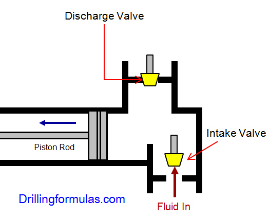
Pressure relief valves are installed on mud pumps in order to prevent an overpressure which could result in a serious damage of the pump and serious or fatal injury to personnel.
The discharge pressure is routed to the closer mud tank, via a 3” XXS line clamped strongly on tank side . Mud is flowing into the mud tank until line bled off, bearing in mind that minimum slope is required to avoid mud settling in pipe ( around 1 inch/meter).
Discharge pressure losses close to the maximum preset pressure.The Pressure relief valves are usually installed on a upper point of the discharge side of the mud pumps.
When two (or more) pumps are arranged in serial their resulting pump performance curve is obtained by adding theirheads at the same flow rate as indicated in the figure below.
Centrifugal pumps in series are used to overcome larger system head loss than one pump can handle alone. for two identical pumps in series the head will be twice the head of a single pump at the same flow rate - as indicated with point 2.
With a constant flowrate the combined head moves from 1 to 2 - BUTin practice the combined head and flow rate moves along the system curve to point 3. point 3 is where the system operates with both pumps running
When two or more pumps are arranged in parallel their resulting performance curve is obtained by adding the pumps flow rates at the same head as indicated in the figure below.
Centrifugal pumps in parallel are used to overcome larger volume flows than one pump can handle alone. for two identical pumps in parallel and the head kept constant - the flow rate doubles compared to a single pump as indicated with point 2
Note! In practice the combined head and volume flow moves along the system curve as indicated from 1 to 3. point 3 is where the system operates with both pumps running
In practice, if one of the pumps in parallel or series stops, the operation point moves along the system resistance curve from point 3 to point 1 - the head and flow rate are decreased.

We provide hydraulic components & repair services for industrial applications like paper mills, saw mills, steel mills, recycling plants, oil & gas applications and mobile applications, including construction, utility, mining, agricultural and marine equipment. This includes hydraulic pumps, motors, valves, servo/prop valves, PTOs, cylinders & parts.


 8613371530291