
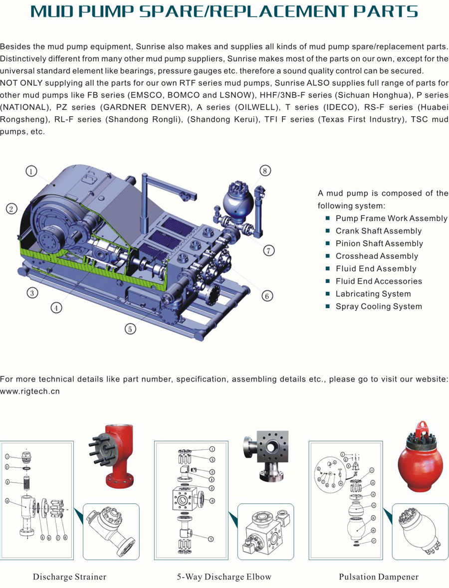
mud pump function free sample

The most common scheme for transmitting measurement information utilizes the drilling fluid within the borehole as a transmission medium for acoustic waves modulated to represent the measurement information. Typically, drilling fluid or "mud" is circulated downward through the drill string and drill bit and upward through the annulus defined by the portion of the borehole surrounding the drill string. The drilling fluid not only removes drill cuttings and maintains a desired hydrostatic pressure in the borehole, but cools the drill bit. In a species of the technique referred to above, a downhole acoustic transmitter known as a rotary valve or "mud siren", repeatedly interrupts the flow of the drilling fluid, and this causes a varying pressure wave to be generated in the drilling fluid at a frequency that is proportional to the rate of interruption. Logging data is transmitted by modulating the acoustic carrier as a function of the downhole measured data.
One difficulty in transmitting measurement information via the drilling mud is that the signal received is typically of low amplitude relative to the noise generated by the mud pumps which circulate the mud, as the downhole signal is generated remote from the uphole sensors while the mud pumps are close to the uphole sensors. In particular, where the downhole tool generates a pressure wave that is phase modulated to encode binary data, such as is disclosed in U.S. Pat. No. 4,847,815 and assigned to the assignee hereof, and where the periodic noise sources are at frequencies which are at or near the frequency of the carrier wave (e.g. 12 Hz), difficulties arise.
Mud pumps are large positive displacement pumps which generate flow by moving a piston back and forth within a cylinder while simultaneously opening and closing intake and exhaust valves. A mud pump typically has three pistons attached to a common drive shaft. These pistons are one hundred and twenty degrees out of phase with one another to minimize pressure variations. Mud pump noise is caused primarily by pressure variations while forcing mud through the exhaust valve.
The fundamental frequency in Hertz of the noise generated by the mud pumps is equal to the strokes per minute of the mud pump divided by sixty. Due to the physical nature and operation of mud pumps, harmonics are also generated, leading to noise peaks of varying amplitude at all integer values of the fundamental frequency. The highest amplitudes generally occur at integer multiples of the number of pistons per pump times the fundamental frequency, e.g., 3F, 6F, 9F, etc. for a pump with three pistons.
Mud pumps are capable of generating very large noise peaks if pump pressure variations are not dampened. Thus, drilling rigs are typically provided with pulsation dampeners at the output of each pump. Despite the pulsation dampeners, however, the mud pump noise amplitude is typically much greater than the amplitude of the signal being received from the downhole acoustic transmitter. To reduce or eliminate the mud pump noise so that the downhole signal can be recovered, different techniques have been proposed, such as may be found in U.S. Pat. Nos. 3,488,629 to Claycomb, 3,555,504 to Fields, 3,716,830 to Garcia, 4,215,425 to Waggener, 4,215,427 to Waggener et al., 4,262,343 to Claycomb, 4,590,593 to Rodney, and 4,642,800 to Umeda. What is common to all of the techniques is that they try to eliminate the mud pump noise by adding the mud pump noise to an inverted version of itself. Most of the techniques utilize two sensors in the mud stream (usually two pressure sensors) and take the difference of signals in an attempt to cancel the mud pump noise without canceling the data signal. Various of the techniques require particular physical arrangements.
The Umeda U.S. Pat. No. 4,642,800 takes a slightly different approach to eliminating mud pump noise. Umeda teaches that an average pump signature may be found by obtaining the pump signatures in the presence of data over a certain number of pump cycles. The updated average pump signature is corrected by interpolation to match the current pump cycle length and is subtracted from the current pump signature to provide the residual data signal. While the technique disclosed in Umeda may be effective for particular arrangements, it has several drawbacks. First, because Umeda averages pump signatures which include data pulses, unless the effect of the data signal over any averaging period is zero (i.e. non-carrier frequency systems), the data signal which is to be recovered will tend to be undesirably subtracted from itself. Second, because Umeda uses only a single strobe per pump cycle, estimates (e.g. interpolations) are utilized which can introduce significant error. Third, Umeda does not disclose in detail how to treat a multi-pump system. In particular, if Umeda assumes that the pump signature for each pump of a multi-pump system is the same as it would be for a single pump system, large errors are introduced in attempting to cancel out the pump noise, as pumps which are working in multi-pump systems will have different signatures than they would it they were working in a single pump system. In addition, because estimates are required for each pump in the multi-pump system, additional error in the multi-pump system is introduced.
It is therefore an object of the invention to provide methods and systems for accurately recovering data signals introduced into drilling mud in the presence of mud pump noise.
It is another object of the invention to provide methods and systems for accurately recovering logging-while-drilling (LWD) or measurement-while-drilling (MWD) information which is modulated in drilling mud by correlating mud pump piston positions to a mud pressure signature in a calibration procedure.
It is a further object of the invention to provide methods and systems for accurately obtaining LWD or MWD information in multiple mud pump systems by allocating noise attributable to each mud pump and by tracking the mud pump piston position of each mud pump.
Another object of the invention is to provide method and systems for recovering LWD or MWD information transmitted through drilling mud by varying the pressure of the drilling mud regardless of the manner in which the information is coded.
In accord with the objects of the invention, methods for recovering a LWD or MWD data signal in the presence of mud pump noise are provided, and generally comprise calibrating the drilling mud pressure as a function of the mud pump piston position, and then tracking the piston position during transmission of the LWD or MWD data signal and using the calibration information to subtract out the mud pump noise. More particularly, calibration is accomplished in the absence of the LWD or MWD data signal to provide a correlation between mud pump piston position and the drilling mud pressure; i.e., the pressure signature as a function of mud pump piston position is obtained. Then, when the LWD or MWD data signal is being provided, the mud pump piston position is tracked such that the pressure due to the pump can be subtracted; i.e., by knowing the mud pump piston position, the pressure due to the mud pump is found and subtracted from the total received signal to provide the LWD or MWD signal. Where a plurality of mud pumps are used, calibration is accomplished by running the mud pumps together in the absence of the LWD or MWD data signal, and processing the received mud pressure signals in the Fourier domain to allocated respective portions of the mud pressure signals to respective mud pumps such that each mud pump is provided with a signature as a function of its own piston position. With the piston position of each mud pump being tracked, the sum of the mud pressure signals generated by the mud pumps based on their piston positions is subtracted from the total received signal to provide the LWD or MWD signal.
According to a preferred aspect of the invention, the calibration procedure is periodically repeated, e.g., each time additional pipe is added to the drill string, thereby eliminating the effects of depth and mud property variation on the system.
FIGS. 8a, 8b, and 8c are respectively the total pump signal, and the signals from pump one and pump two in the multiple pump system calibrated according to FIGS 7a and 7b.
Referring to FIG. 1, the operation of the present invention in a typical drilling arrangement is illustrated schematically. Drilling mud 10 is picked up from mud pit 11 by one or more mud pumps 12 which are typically of the piston reciprocating type. The mud 10 is circulated through mud line 13, down through the drill string 14, through the drill bit 15, and back to the surface of the formation via the annulus 16 between the drill stem and the wall of the well bore 29. Upon reaching the earth"s surface 31, the mud is discharged through line 17 back into the mud pit 11 where cuttings of rock or other well debris are allowed to settle out before the mud is recirculated.
A downhole pressure pulse signaling device 18 is incorporated in the drill string for transmission of data signals derived during the drilling operation by the measurement instrument package 19. Signaling device 18 may be of the valve or variable orifice type which generates pressure pulses in the drilling fluid by varying the speed of flow. A preferred signaling device which generates sinusoidal signals is disclosed in U.S. Pat. No. 4,847,815 assigned to the assignee hereof. Data signals are encoded in a desired form by appropriate electronic means in the downhole tool. Arrows 21, 22, and 23 illustrate the path taken by the pressure pulses provided by the downhole signaling device 18 under typical well conditions. Pump 12 also produces pressure pulses in the mud line 13 and these are indicated by arrows, 24, 25, 26 and 26a which also illustrate the flow of the mud through the annulus 16.
In order for the downhole pressure pulse signals to be recoverable at the surface, some means must be provided to remove or substantially eliminate the portion of the mud pressure signal due to the mud pumps. Subsystem 30, including pressure transducer 32, mud pump piston position sensors 34, and computer or processor 36, comprises such a means.
The preferred pressure transducer 32 of subsystem 30 is a piezoelectric pressure transducer which provides an analog signal which is preferably bandpass filtered by a filter (not shown) or by the computer 36. The preferred mud pump piston position sensor 34 may either comprise an LVDT which utilizes a linear position transducer, or an RVDT which utilizes a rotary position transducer. The LVDT, as shown in FIG. 2a, has an arm 40a, a rod 42a, and a linear position transducer 44a with leads 46a. Arm 40a is coupled to one of the piston rods 47 of the mud pump 12 as well as to rod 42a of the LVDT. Rod 42a moves coaxially within the linear position transducer 44a, which provides a high precision digital indication of the location of piston 48 in the mud pump 12. The RVDT, as shown in FIG. 2b, has an arm 40b, a cable 42b, and an encoder or rotary position transducer 44b with a spring loaded sheave takeup reel 45b. The RVDT also includes leads 46b. Arm 40b of the RVDT of FIG. 2b is coupled to one of the piston rods 47 of the mud pump 12 as well as to the cable 42b of the RBDT. As arm 40b moves with the pump piston rod 47, the cable 42b is let out or reeled onto the takeup reel 45b takeup reel. The rotation of the takeup reel 45b provides a high precision digital indication of the location of piston 48 in the mud pump 12.
Testing has shown that the drilling mud pressure generated by the mud pump 12 is determined by the position of the mud pump piston for a given set of operating conditions. FIG. 3 illustrates how mud pump piston position correlates to mud pump noise. By coupling the linear position transducer 44a or rotary position transducer 44b to the piston rod 47 of the mud pump, a calibration can be performed that measures the pressure generated as a function of piston position.
The preferred calibration procedure for correlating mud pressure generated as a function of piston position for a single mud pump system is seen in FIG. 4. After the pump noise stabilizes in the system, and before the LWD and MWD tool turns on (i.e. before the data signal starts), the signals output by the position sensor 34 and the signals output by the pressure transducer 32 which are bandpass filtered at 39 are preferably recorded at 52 as related position and pressure arrays 55, 57 in the computer (e.g. in computer memory). Preferably, approximately eight seconds of data (e.g., five to ten pump cycles) are accumulated. Then, averages of the pressure as a function of position are calculated (thereby reducing random pressure variations) at 58 to produced a single position vs. pump noise calibration array 59. Indications of the average calibration array or the inverse thereof are stored and used for canceling mud pump noise as is hereinafter described.
The noise cancellation procedure according to the invention is set forth in FIG. 5. Upon the turning on of the downhole tool and the transmission of LWD or MWD data (hereinafter referred to simply as LWD data for sake of brevity), the position sensor 34 and pressure transducer 32 continue to provide indications of piston location and mud pressure; except that the piston position data is used in real time to determine the electrical signal (based on the calibration array 59) which must be subtracted from the composite LWD/noise signal to cancel the noise component of the signal and leave only the LWD signal. Thus, as shown in FIG. 5, the position sensor signal is sampled at 62 (i.e. based on the position sensor signal, the average calibration array is accessed and a corresponding pump noise is provided), and the corresponding pump noise pressure 64 is subtracted at 66 from the real time sensed pressure 32 which was bandpass filtered at 67 to eliminate high frequency components. The difference between the real time sensed pressure and the pump noise pressure provides an indication of the LWD data signal 68.
Test results of a real time sensed pressure pump noise signal are seen in FIG. 6a, where the amplitude of the signal as expressed in dB (in 10 dB increments) is plotted versus the frequency expressed in Hz (in 4 Hz increments). As seen in FIG. 6a, the noise signal includes several peaks having amplitudes between -10 dB and 0 dB, and even includes a peak having an amplitude exceeding 10 dB. The noise signal of FIG. 6a was then subjected to the noise cancellation procedure of FIG. 5. The noise signal remaining after mud pump noise cancellation is seen in FIG. 6b, and shows that the calibration and noise cancellation procedures reduced noise considerably. In fact, the largest remaining noise peak found at about 5 Hz, has an amplitude of approximately -15 dB, which is more than 25 dB less than the largest peak seen in FIG. 6a prior to noise cancellation.
Turing to FIGS. 7, 7a and 7b, a flow chart of the mud pump calibration procedure for a system utilizing two mud pumps is seen. After the pump noise stabilizes in the system, and before the LWD tool turns on (i.e. before the data signal starts), the signals output by each position sensor 34a, 34b and the signal output by the pressure transducer 32 and filtered at 39 by a bandpass filter which measures composite pump noise are recorded as related position arrays 55a, 55b and pressure array 57 in the computer (e.g. in computer memory). Preferably, approximately twelve seconds of data are accumulated in computer memory at 52; FIG. 8a showing an example of the analog pressure signal which is digitized and stored as part of the array. A fast Fourier transform (FFT) of the composite pump noise signal is then conducted at 70 by the computer. As a result of the FFT, the amplitude and phase of all frequencies contained in the composite mud pump noise signal is obtained at 70 (see FIG. 9a). Utilizing the operating speed of each pump which can be computed from the position sensor of each mud pump, the fundamental frequency and harmonics for each pump are calculated at 72. The, at 75, the amplitude and phase information for each fundamental and harmonic frequency are extracted from the FFT and assigned to its source (i.e. a particular one of the mud pumps) to provide results as seen in FIGS. 9b and 9c. Taking an inverse Fourier transform of the frequency spectra of FIGS. 9b and 9c at 76a and 76b, signals attributable to each of the pumps are obtained as seen in FIGS. 8b and 8c. As indicated in FIG. 7b at 58a and 58b, the position of each mud pump position sensor is related to the mud pressure generated by the respective mud pump, and an average of the pressure as a function of position is calculated for each mud pump to produce two position vs. pump noise calibration arrays 59a and 59b. Indications of the average calibration arrays are stored in computer memory and used for canceling mud pump noise as is described above with reference to FIG. 10.
Referring now to FIG. 10, the noise cancellation procedure for a system using multiple mud pumps is seen. Upon the turning on of the downhole tool and the transmission of LWD data, the position sensors 34a and 34b and pressure transducer 32 continue to provide indications of piston location and mud pressure; except that the piston position data is used in real time to determine the electrical signal (based on the calibration arrays 59a and 59b) which must be subtracted from the composite LWD/noise signal to cancel the noise component of the signal and leave only the LWD signal. Thus, as shown in FIG. 10, the position sensor signals are sampled at 62a and 62b (i.e. based on the position sensor signals, the average calibration arrays 59a and 59b are accessed and corresponding pump noises are provided), and the corresponding pump noise pressures 64a and 64b are subtracted at 66 from the real time sensed pressure 32 which was bandpass filtered at 67 to eliminate high frequency components. The difference between the real time sensed pressure and the pump noise pressures provides an indication of the LWD data signal 68. That signal is then decoded according to techniques known in the art which are not part of the present invention.
Test results of a real time sensed pressure containing pump noise for two mud pumps is seen in FIG. 11a where amplitude is plotted against frequency. As seen in FIG. 11a, numerous noise peaks having amplitudes of -20 dB or higher are seen, with the largest peak of about -5 dB at 5 Hz. The pressure signal obtained after utilizing the calibration and noise cancellation steps of FIGS. 7 and 10 in order to substantially cancel mud pump noise from the signal of FIG. 10a is seen in FIG. 10b. As seen in FIG. 10b, the remaining noise is substantially reduced relative to the noise of FIG. 10a, with the largest peak of about -18 dB occurring at approximately 18 Hz.
There have been described and illustrated herein methods and apparatus for canceling mud pump noise in order to recover a logging while drilling signal. While particular embodiments of the invention have been described it is not intended that the the invention be limited exactly thereto, as it is intended that the invention be as broad in scope as the art will allow. Thus, while particular pressure transducers, position sensors, pump-types, computers, FFT programs, and the like have been disclosed, it will be appreciated that other equipment and programs can be utilized effectively. Similarly, while certain preferred data gathering time periods were disclosed prior to running the LWD or MWD tool, it will be appreciated that other time frames could be utilized. Also, while the invention was described with reference to LWD and MWD procedures, it will be appreciated that the terms LWD and MWD are intended to include any other data signaling procedure where data is transmitted in drilling mud in the presence of mud pump noise. Further, while the invention was disclosed with reference to systems utilizing one or two mud pumps, it will be appreciated that the teachings equally apply to systems utilizing additional mud pumps. All that is required is that the pressure signature of each mud pump relative to its piston position be obtained via transforming the total signal into the Fourier domain, dividing the Fourier response among the various mud pumps based on their fundamental and harmonic frequencies, and converting the responses back into respective pressure signatures. It will be understood, of course, that where two mud pumps are working in unison (i.e. at the same frequency), their signatures can be treated together. Therefore, it will be apparent to those skilled in the art that other changes and modifications may be made to the invention as described in the specification without departing from the spirit and scope of the invention as so claimed.

I’ve run into several instances of insufficient suction stabilization on rigs where a “standpipe” is installed off the suction manifold. The thought behind this design was to create a gas-over-fluid column for the reciprocating pump and eliminate cavitation.
When the standpipe is installed on the suction manifold’s deadhead side, there’s little opportunity to get fluid into all the cylinders to prevent cavitation. Also, the reciprocating pump and charge pump are not isolated.
The suction stabilizer’s compressible feature is designed to absorb the negative energies and promote smooth fluid flow. As a result, pump isolation is achieved between the charge pump and the reciprocating pump.
The isolation eliminates pump chatter, and because the reciprocating pump’s negative energies never reach the charge pump, the pump’s expendable life is extended.
Investing in suction stabilizers will ensure your pumps operate consistently and efficiently. They can also prevent most challenges related to pressure surges or pulsations in the most difficult piping environments.

The 2,200-hp mud pump for offshore applications is a single-acting reciprocating triplex mud pump designed for high fluid flow rates, even at low operating speeds, and with a long stroke design. These features reduce the number of load reversals in critical components and increase the life of fluid end parts.
The pump’s critical components are strategically placed to make maintenance and inspection far easier and safer. The two-piece, quick-release piston rod lets you remove the piston without disturbing the liner, minimizing downtime when you’re replacing fluid parts.

A comprehensive range of mud pumping, mixing, and processing equipment is designed to streamline many essential but time-consuming operational and maintenance procedures, improve operator safety and productivity, and reduce costly system downtime.

If you run a mud rig, you have probably figured out that the mud pump is the heart of the rig. Without it, drilling stops. Keeping your pump in good shape is key to productivity. There are some tricks I have learned over the years to keeping a pump running well.
First, you need a baseline to know how well your pump is doing. When it’s freshly rebuilt, it will be at the top efficiency. An easy way to establish this efficiency is to pump through an orifice at a known rate with a known fluid. When I rig up, I hook my water truck to my pump and pump through my mixing hopper at idle. My hopper has a ½-inch nozzle in it, so at idle I see about 80 psi on the pump when it’s fresh. Since I’m pumping clear water at a known rate, I do this on every job.
As time goes on and I drill more hole, and the pump wears, I start seeing a decrease in my initial pressure — 75, then 70, then 65, etc. This tells me I better order parts. Funny thing is, I don’t usually notice it when drilling. After all, I am running it a lot faster, and it’s hard to tell the difference in a few gallons a minute until it really goes south. This method has saved me quite a bit on parts over the years. When the swabs wear they start to leak. This bypass pushes mud around the swab, against the liners, greatly accelerating wear. By changing the swab at the first sign of bypass, I am able to get at least three sets of swabs before I have to change liners. This saves money.
Before I figured this out, I would sometimes have to run swabs to complete failure. (I was just a hand then, so it wasn’t my rig.) When I tore the pump down to put in swabs, lo-and-behold, the liners were cut so badly that they had to be changed too. That is false economy. Clean mud helps too. A desander will pay for itself in pump parts quicker than you think, and make a better hole to boot. Pump rods and packing last longer if they are washed and lubricated. In the oilfield, we use a petroleum-based lube, but that it not a good idea in the water well business. I generally use water and dish soap. Sometimes it tends to foam too much, so I add a few tablets of an over the counter, anti-gas product, like Di-Gel or Gas-Ex, to cut the foaming.
Maintenance on the gear end of your pump is important, too. Maintenance is WAY cheaper than repair. The first, and most important, thing is clean oil. On a duplex pump, there is a packing gland called an oil-stop on the gear end of the rod. This is often overlooked because the pump pumps just as well with a bad oil-stop. But as soon as the fluid end packing starts leaking, it pumps mud and abrasive sand into the gear end. This is a recipe for disaster. Eventually, all gear ends start knocking. The driller should notice this, and start planning. A lot of times, a driller will change the oil and go to a higher viscosity oil, thinking this will help cushion the knock. Wrong. Most smaller duplex pumps are splash lubricated. Thicker oil does not splash as well, and actually starves the bearings of lubrication and accelerates wear. I use 85W90 in my pumps. A thicker 90W140 weight wears them out a lot quicker. You can improve the “climbing” ability of the oil with an additive, like Lucas, if you want. That seems to help.
Outside the pump, but still an important part of the system, is the pop-off, or pressure relief valve. When you plug the bit, or your brother-in-law closes the discharge valve on a running pump, something has to give. Without a good, tested pop-off, the part that fails will be hard to fix, expensive and probably hurt somebody. Pop-off valve are easily overlooked. If you pump cement through your rig pump, it should be a standard part of the cleanup procedure. Remove the shear pin and wash through the valve. In the old days, these valves were made to use a common nail as the shear pin, but now nails come in so many grades that they are no longer a reliable tool. Rated shear pins are available for this. In no case should you ever run an Allen wrench! They are hardened steel and will hurt somebody or destroy your pump.
One last thing that helps pump maintenance is a good pulsation dampener. It should be close to the pump discharge, properly sized and drained after every job. Bet you never thought of that one. If your pump discharge goes straight to the standpipe, when you finish the job your standpipe is still full of fluid. Eventually the pulsation dampener will water-log and become useless. This is hard on the gear end of the pump. Open a valve that drains it at the end of every job. It’ll make your pump run smoother and longer.

When choosing a size and type of mud pump for your drilling project, there are several factors to consider. These would include not only cost and size of pump that best fits your drilling rig, but also the diameter, depth and hole conditions you are drilling through. I know that this sounds like a lot to consider, but if you are set up the right way before the job starts, you will thank me later.
Recommended practice is to maintain a minimum of 100 to 150 feet per minute of uphole velocity for drill cuttings. Larger diameter wells for irrigation, agriculture or municipalities may violate this rule, because it may not be economically feasible to pump this much mud for the job. Uphole velocity is determined by the flow rate of the mud system, diameter of the borehole and the diameter of the drill pipe. There are many tools, including handbooks, rule of thumb, slide rule calculators and now apps on your handheld device, to calculate velocity. It is always good to remember the time it takes to get the cuttings off the bottom of the well. If you are drilling at 200 feet, then a 100-foot-per-minute velocity means that it would take two minutes to get the cuttings out of the hole. This is always a good reminder of what you are drilling through and how long ago it was that you drilled it. Ground conditions and rock formations are ever changing as you go deeper. Wouldn’t it be nice if they all remained the same?
Centrifugal-style mud pumps are very popular in our industry due to their size and weight, as well as flow rate capacity for an affordable price. There are many models and brands out there, and most of them are very good value. How does a centrifugal mud pump work? The rotation of the impeller accelerates the fluid into the volute or diffuser chamber. The added energy from the acceleration increases the velocity and pressure of the fluid. These pumps are known to be very inefficient. This means that it takes more energy to increase the flow and pressure of the fluid when compared to a piston-style pump. However, you have a significant advantage in flow rates from a centrifugal pump versus a piston pump. If you are drilling deeper wells with heavier cuttings, you will be forced at some point to use a piston-style mud pump. They have much higher efficiencies in transferring the input energy into flow and pressure, therefore resulting in much higher pressure capabilities.
Piston-style mud pumps utilize a piston or plunger that travels back and forth in a chamber known as a cylinder. These pumps are also called “positive displacement” pumps because they literally push the fluid forward. This fluid builds up pressure and forces a spring-loaded valve to open and allow the fluid to escape into the discharge piping of the pump and then down the borehole. Since the expansion process is much smaller (almost insignificant) compared to a centrifugal pump, there is much lower energy loss. Plunger-style pumps can develop upwards of 15,000 psi for well treatments and hydraulic fracturing. Centrifugal pumps, in comparison, usually operate below 300 psi. If you are comparing most drilling pumps, centrifugal pumps operate from 60 to 125 psi and piston pumps operate around 150 to 300 psi. There are many exceptions and special applications for drilling, but these numbers should cover 80 percent of all equipment operating out there.
The restriction of putting a piston-style mud pump onto drilling rigs has always been the physical size and weight to provide adequate flow and pressure to your drilling fluid. Because of this, the industry needed a new solution to this age-old issue.
As the senior design engineer for Ingersoll-Rand’s Deephole Drilling Business Unit, I had the distinct pleasure of working with him and incorporating his Centerline Mud Pump into our drilling rig platforms.
In the late ’90s — and perhaps even earlier — Ingersoll-Rand had tried several times to develop a hydraulic-driven mud pump that would last an acceptable life- and duty-cycle for a well drilling contractor. With all of our resources and design wisdom, we were unable to solve this problem. Not only did Miller provide a solution, thus saving the size and weight of a typical gear-driven mud pump, he also provided a new offering — a mono-cylinder mud pump. This double-acting piston pump provided as much mud flow and pressure as a standard 5 X 6 duplex pump with incredible size and weight savings.
The true innovation was providing the well driller a solution for their mud pump requirements that was the right size and weight to integrate into both existing and new drilling rigs. Regardless of drill rig manufacturer and hydraulic system design, Centerline has provided a mud pump integration on hundreds of customer’s drilling rigs. Both mono-cylinder and duplex-cylinder pumps can fit nicely on the deck, across the frame or even be configured for under-deck mounting. This would not be possible with conventional mud pump designs.
The second generation design for the Centerline Mud Pump is expected later this year, and I believe it will be a true game changer for this industry. It also will open up the application to many other industries that require a heavier-duty cycle for a piston pump application.

Created specifically for drilling equipment inspectors and others in the oil and gas industry, the Oil Rig Mud Pump Inspection app allows you to easily document the status and safety of your oil rigs using just a mobile device. Quickly resolve any damage or needed maintenance with photos and GPS locations and sync to the cloud for easy access. The app is completely customizable to fit your inspection needs and works even without an internet signal.Try Template

This website uses cookies to improve your experience while you navigate through the website. Out of these cookies, the cookies that are categorized as necessary are stored on your browser as they are as essential for the working of basic functionalities of the website. We also use third-party cookies that help us analyze and understand how you use this website. These cookies will be stored in your browser only with your consent. You also have the option to opt-out of these cookies. But opting out of some of these cookies may have an effect on your browsing experience.
There are many different ways to drill a domestic water well. One is what we call the “mud rotary” method. Whether or not this is the desired and/or best method for drilling your well is something more fully explained in this brief summary.
One advantage of drilling with compressed air is that it can tell you when you have encountered groundwater and gives you an indication how much water the borehole is producing. When drilling with water using the mud rotary method, the driller must rely on his interpretation of the borehole cuttings and any changes he can observe in the recirculating fluid. Mud rotary drillers can also use borehole geophysical tools to interpret which zones might be productive enough for your water well.
The mud rotary well drilling method is considered a closed-loop system. That is, the mud is cleaned of its cuttings and then is recirculated back down the borehole. Referring to this drilling method as “mud” is a misnomer, but it is one that has stuck with the industry for many years and most people understand what the term actually means.
The water is carefully mixed with a product that should not be called mud because it is a highly refined and formulated clay product—bentonite. It is added, mixed, and carefully monitored throughout the well drilling process.
The purpose of using a bentonite additive to the water is to form a thin film on the walls of the borehole to seal it and prevent water losses while drilling. This film also helps support the borehole wall from sluffing or caving in because of the hydraulic pressure of the bentonite mixture pressing against it. The objective of the fluid mixture is to carry cuttings from the bottom of the borehole up to the surface, where they drop out or are filtered out of the fluid, so it can be pumped back down the borehole again.
When using the mud rotary method, the driller must have a sump, a tank, or a small pond to hold a few thousand gallons of recirculating fluid. If they can’t dig sumps or small ponds, they must have a mud processing piece of equipment that mechanically screens and removes the sands and gravels from the mixture. This device is called a “shale shaker.”
The driller does not want to pump fine sand through the pump and back down the borehole. To avoid that, the shale shaker uses vibrating screens of various sizes and desanding cones to drop the sand out of the fluid as it flows through the shaker—so that the fluid can be used again.
Some drillers use compressed air to blow off the well, starting at the first screened interval and slowly working their way to the bottom—blowing off all the water standing above the drill pipe and allowing it to recover, and repeating this until the water blown from the well is free of sand and relatively clean. If after repeated cycles of airlift pumping and recovery the driller cannot find any sand in the water, it is time to install a well development pump.
Additional development of the well can be done with a development pump that may be of a higher capacity than what the final installation pump will be. Just as with cycles of airlift pumping of the well, the development pump will be cycled at different flow rates until the maximum capacity of the well can be determined. If the development pump can be operated briefly at a flow rate 50% greater than the permanent pump, the well should not pump sand.
Mud rotary well drillers for decades have found ways to make this particular system work to drill and construct domestic water wells. In some areas, it’s the ideal method to use because of the geologic formations there, while other areas of the country favor air rotary methods.
To learn more about the difference between mud rotary drilling and air rotary drilling, click the video below. The video is part of our “NGWA: Industry Connected” YouTube series:
Cavitation is an undesirable condition that reduces pump efficiency and leads to excessive wear and damage to pump components. Factors that can contribute to cavitation, such as fluid velocity and pressure, can sometimes be attributed to an inadequate mud system design and/or the diminishing performance of the mud pump’s feed system.
When a mud pump has entered full cavitation, rig crews and field service technicians will see the equipment shaking and hear the pump “knocking,” which typically sounds like marbles and stones being thrown around inside the equipment. However, the process of cavitation starts long before audible signs reveal themselves – hence the name “the silent killer.”
Mild cavitation begins to occur when the mud pump is starved for fluid. While the pump itself may not be making noise, damage is still being done to the internal components of the fluid end. In the early stages, cavitation can damage a pump’s module, piston and valve assembly.
The imperceptible but intense shock waves generated by cavitation travel directly from the fluid end to the pump’s power end, causing premature vibrational damage to the crosshead slides. The vibrations are then passed onto the shaft, bull gear and into the main bearings.
If not corrected, the vibrations caused by cavitation will work their way directly to critical power end components, which will result in the premature failure of the mud pump. A busted mud pump means expensive downtime and repair costs.
To stop cavitation before it starts, install and tune high-speed pressure sensors on the mud suction line set to sound an alarm if the pressure falls below 30 psi.
Although the pump may not be knocking loudly when cavitation first presents, regular inspections by a properly trained field technician may be able to detect moderate vibrations and slight knocking sounds.
Gardner Denver offers Pump University, a mobile classroom that travels to facilities and/or drilling rigs and trains rig crews on best practices for pumping equipment maintenance.
Severe cavitation will drastically decrease module life and will eventually lead to catastrophic pump failure. Along with downtime and repair costs, the failure of the drilling pump can also cause damage to the suction and discharge piping.
When a mud pump has entered full cavitation, rig crews and field service technicians will see the equipment shaking and hear the pump ‘knocking’… However, the process of cavitation starts long before audible signs reveal themselves – hence the name ‘the silent killer.’In 2017, a leading North American drilling contractor was encountering chronic mud system issues on multiple rigs. The contractor engaged in more than 25 premature module washes in one year and suffered a major power-end failure.
Gardner Denver’s engineering team spent time on the contractor’s rigs, observing the pumps during operation and surveying the mud system’s design and configuration.
The engineering team discovered that the suction systems were undersized, feed lines were too small and there was no dampening on the suction side of the pump.
Following the implementation of these recommendations, the contractor saw significant performance improvements from the drilling pumps. Consumables life was extended significantly, and module washes were reduced by nearly 85%.
Although pump age does not affect its susceptibility to cavitation, the age of the rig can. An older rig’s mud systems may not be equipped for the way pumps are run today – at maximum horsepower.

A mud pump (sometimes referred to as a mud drilling pump or drilling mud pump), is a reciprocating piston/plunger pump designed to circulate drilling fluid under high pressure (up to 7,500 psi or 52,000 kPa) down the drill string and back up the annulus. A mud pump is an important part of the equipment used for oil well drilling.
Mud pumps can be divided into single-acting pump and double-acting pump according to the completion times of the suction and drainage acting in one cycle of the piston"s reciprocating motion.
Mud pumps come in a variety of sizes and configurations but for the typical petroleum drilling rig, the triplex (three piston/plunger) mud pump is used. Duplex mud pumps (two piston/plungers) have generally been replaced by the triplex pump, but are still common in developing countries. Two later developments are the hex pump with six vertical pistons/plungers, and various quintuplexes with five horizontal piston/plungers. The advantages that these new pumps have over convention triplex pumps is a lower mud noise which assists with better measurement while drilling (MWD) and logging while drilling (LWD) decoding.
The fluid end produces the pumping process with valves, pistons, and liners. Because these components are high-wear items, modern pumps are designed to allow quick replacement of these parts.
To reduce severe vibration caused by the pumping process, these pumps incorporate both a suction and discharge pulsation dampener. These are connected to the inlet and outlet of the fluid end.
The pressure of the pump depends on the depth of the drilling hole, the resistance of flushing fluid (drilling fluid) through the channel, as well as the nature of the conveying drilling fluid. The deeper the drilling hole and the greater the pipeline resistance, the higher the pressure needed.
With the changes of drilling hole diameter and depth, the displacement of the pump can be adjusted accordingly. In the mud pump mechanism, the gearbox or hydraulic motor is equipped to adjust its speed and displacement. In order to accurately measure the changes in pressure and displacement, a flow meter and pressure gauge are installed in the mud pump.
The construction department should have a special maintenance worker that is responsible for the maintenance and repair of the machine. Mud pumps and other mechanical equipment should be inspected and maintained on a scheduled and timely basis to find and address problems ahead of time, in order to avoid unscheduled shutdown. The worker should attend to the size of the sediment particles; if large particles are found, the mud pump parts should be checked frequently for wear, to see if they need to be repaired or replaced. The wearing parts for mud pumps include pump casing, bearings, impeller, piston, liner, etc. Advanced anti-wear measures should be adopted to increase the service life of the wearing parts, which can reduce the investment cost of the project, and improve production efficiency. At the same time, wearing parts and other mud pump parts should be repaired rather than replaced when possible.

Kverneland, Hege, Kyllingstad, Åge, and Magne Moe. "Development and Performance Testing of the Hex Mud Pump." Paper presented at the SPE/IADC Drilling Conference, Amsterdam, Netherlands, February 2003. doi: https://doi.org/10.2118/79831-MS

Drilling mud is most commonly used in the process of drilling boreholes for a variety of reasons such as oil and gas extraction as well as core sampling. The mud plays an important role in the drilling process by serving numerous functions. The main function it is utilized for is as a lubricating agent. A large amount of friction is generated as drilling occurs which has the potential to damage the drill or the formation being drilled. The mud aids in the decrease in friction as well as lowering the heat of the drilling. It also acts a carrier for the drilled material so it becomes suspended in the mud and carried to the surface.
Using a Moyno progressive cavity pump, the drilling mud with suspended material can be pumped through a process to remove the solids and reuse the cleaned mud for further drilling.

A mud pump or drilling mud pump is used to circulate drilling mud on a drilling rig at high pressure. The mud is circulated down through the drill string, and back through the annulus at high pressures. Mud pumps are typically positive displacement pumps, otherwise known as reciprocating pumps. Mud pumps are ideal wherever a lot of fluid needs to be pumped under high pressure. They are considered an essential part of most oil well drilling rigs. Mud pumps can deliver high concentration and high viscosity slurry in a stable flow, making them adaptable to many uses.
Mud pumps are special-purpose pumps, particularly used for moving and circulating drilling fluids and other similar fluids in several applications such as mining and onshore and offshore oil & gas. Mud pumps are a piston/plunger cylinder systems that are used to transfer fluids at substantially high pressures. These pumps are operated in rugged and hostile environments and thus, are bulky and robust. These pumps can draw power from various sources. However, electricity and diesel are widely used sources. Diesel-driven mud pumps are well suited for remote and isolated applications where electricity is not continuously available. These pumps have two major sub-assemblies namely fluid and power ends. The power end consumes power and drives the fluid end to pump the mud. The mud pump market is largely driven by the rising demand for oil & gas.
COVID-19 pandemic has shut-down the production of various products in the mud pumps industry, mainly owing to the prolonged lockdown in major global countries. This has hampered the growth of mud pumps market significantly from last few months, as is likely to continue during 2020.
A mud pump has its use in drilling fluids, mining and various purpose like that and its increase in demand for such purpose is the factor that drives its growth.increased demand for directional and horizonal drilling
The main drivers for the growth of this market are the increased demand for directional and horizonal drilling, higher pressure handling capabilities, and a number of new oil discoveries. The global rise in demand for energy boosts the global mud pumps as according to its immense use in market. However, high cost of drilling, environmental risks, and changing government regulations for energy and power may hinder the growth of the market.Innovation in technology
Innovation in technology is the key for further growth for example, MTeq uses Energy Recovery’s Pressure exchanger technology in the drilling industry, as the ultimate engineered solution to increase productivity and reduce operating costs in pumping process by rerouting rough fluids away from high-pressure pumps, which helps reduce the cost of maintenance for operators. As there is increase in technology , so these kind of new innovations in traditional ways that eases the work and reduce the difficulties becomes the factor to increase the growth of market.
Key benefits of the report:This study presents the analytical depiction of the mud pumps market along with the current trends and future estimations to determine the future of the market
Key Market Players Kirloskar Ebara Pumps Limited, Flowserve, Goulds Pumps, Shijiazhuang Industrial Pump Factory Co. Ltd., Halliburton, Xylem Inc., KSB Group, Excellence Pump Industry Co. Ltd., Weir Group, SRS Crisafulli Inc.


 8613371530291