
mud pump maintenance manual brands
Thanks for using F series mud pumps produced by Baoji Oilfield Machinery Co., Ltd. The outline dimension, frame, and fluid end of F-1300 and 1600 mud pump are the same, only the bearing and gear pair of power end are different. For convenience of customer, this manual introduces these two kinds mud pumps at the same time.
(3.206) Note: 1. Based on 100% volumetric efficiency and 90% mechanical efficiency. Recommended strokes and input power for continuous service. Table 1B Performance data of F-1300/1600 Mud Pump Liner Diameter, in & Rating pressure, MPa(Psi) 6 3/4 6 1/2 6 1/4...
Fig. 2 1.2.1. Ground Installation When ground installation is going on, 8 pieces of 76mm×305mm boards is cushioned in the direction of pump skid, as indicated in Fig.2. The base of boards should be 300mm wider than that of pump skid beam.
Fig. 3 1.2.3. Installations of Driving Device The drive between the mud pumps and prime mover should be adopted V-belts or multi-row chains drive, which is installed with precision to assure longest service life and minimum possibility of unexpected or undesirable shutdowns due to drive failures. When installing the drive sheave or sprocket, make sure all grease or rust preventative is removed clearly from the shaft end and the matched bore.
Stationary spray pipes have been used on F-series pumps Ref. Fig 5. It consists of a fixture frame (1), steel pipe (2) and spray nozzle (3), it makes cooling fluid spray to piston and liner. Adjust cooling water supply to the manifold and inspect spray nozzle operation very often to make sure the nozzle is pointed directly at the piston.
Instruction Manual for F1300/1600 Mud Pump 1.6.2. Liners Installs wear-resisting plate seal (1) in counter bore of fluid end (see Fig. 8). Install wear-resisting plate (2) through studs until it seats against fluid end. Mount liner flange (3) over studs with the starting thread at the 5 o’clock position and tighten bolts with 640~690N.m (470~510ft.lbs) torque.
Instruction Manual for F1300/1600 Mud Pump 1.6.6. Valve Cover Install valve cover seal ring (18) into bore, and after grease the valve cover seal area and threads area, tighten the valve covers into place using a sledge hammer and bar. 1.6.7 Discharge Manifold API 5"...
Instruction Manual for F1300/1600 Mud Pump shield ○ 8 is used for lifting dampener assembly. Before assembly thoroughly clean ring groove, gasket ring ○ 1 and groove of mating flange and coat with grease. Lifting the dampener to the corresponding position of mud pump discharge line, screw nut (R4) with 950~1265N.m (700~935ft.lbs) torque.
Instruction Manual for F1300/1600 Mud Pump Fig.15 (1) Filter (2) Oil distributor (3) Oil line (3A) Spray nozzle (4) Main bearing oil line (4A) Oil distributor (5)Pressure gauge (6) Relief valve (7) Oil trough (8) Oil tube (9) Lubrication pump A pressure relief valve (6) is mounted to the oil distributor (2) to prevent excess pressure from damaging oil pump and drive.
Instruction Manual for F1300/1600 Mud Pump Fig.18 (1) Cover (2) Bolt (3) Retainer ring (4) Bolt (5) Bearing retainer ring (7) Retainer ring (8) Bolt (8A) Inner hex bolts (9) Main bearing (10) Right bearing sleeve (11) Left bearing sleeve (12) Outer retainer ring (13) Connecting rod bearing (14) Inner retainer ring (15) Bolt (16) Main bearing retainer (17) Inner race retainer (18) Bolt (19) Crosshead bearing 1) Install gear ring and check run-out.
Instruction Manual for F1300/1600 Mud Pump valve spring, change the damaged one. Check if the locknuts of piston are corrosive or damaged. Change if they are Weekly damaged (normally, change after using three times). Weekly Check the filter screen of lubricating system. Clean it if it is plugged. Weekly Loosen the plug of drain flange, discharge the dirt and water in the oil pool.
Instruction Manual for F1300/1600 Mud Pump become sealed off and the air gets charging piping or change the discharge reduces or no mud into the pump. gasket. discharged. 2. The suction filter screen is 2. Stop the pump and clean the plugged.
Instruction Manual for F1300/1600 Mud Pump F-1300/1600 Spare Parts List F-1300/1600 Tool List F-1300/1600 Mud Pump General Assembly 11 43 54 6 56 17 8 36 B向...
Instruction Manual for F1300/1600 Mud Pump F-1300/1600 Drilling Mud Pump Drawing No. Item Description F-1300 F-1600 Frame assembly AH1301020100 AH1301020100 Crank shaft assembly AH1301020200 AH1601020100 Pinion shaft assembly AH1301020300 AH1601020200 Crosshead assembly AH1301020400 AH1301020400 Fluid end assembly AH1301020500 AH1301020500 Power...
Instruction Manual for F1300/1600 Mud Pump Drawing No. Item Description F-1300 F-1600 Flange T508-1002 T508-1002 KB-75 Dampener AK75350200 AK75350200 JA-3 Shear relieve valve AH0000060200 AH0000060200 Connection tube T510-1002 T510-1002 Cover plate AH1301011800 AH1301011800 Right-angle joint T511-1002 T511-1002 Bolt 1/2-13UNCX1 T500-1001...
Instruction Manual for F1300/1600 Mud Pump Crankshaft Assembly Fluid End 13 14 Drawing No. Item Description F-1300 F-1600 Main bearing AH130101020100 AH130101020100 cover Bearing sleeve, AH1301010202 AH1601020101 right Gasket AH1301010203 AH1301010203 Inner race AH1301010204 AH1301010204 retainer Outer race AH130101020500 AH160101010200...
Instruction Manual for F1300/1600 Mud Pump Drawing No. Item Description F-1300 F-1600 AH130101020100 AH130101020100 Locating ring (I) AH1301020201 AH1601020101 Hollow crankshaft AH1301010203 AH1301010203 Locating ring (II) AH1301010204 AH1301010204 Gear ring AH130101020500 AH160101010200 Piston 1/2-8UN Bolt 1 1/2-8UNx5 AH1301020202 AH1601020102 AH1301020203...
Instruction Manual for F1300/1600 Mud Pump Drawing No. Item Description F-1300 F-1600 AH1301010218 AH1601010108 Gear ring (split one) 420501036160200000 420501036160200000 Bolt 1 1/2-8UN× F-1300/1600 Pinion Shaft Assembly 11 16 Fluid End Drawing No. Item Description F-1300 F-1600 AH1301020301 AH1301020301 Key 2″×2″×11 3/8″ AH1301020302 AH1601020201...
Instruction Manual for F1300/1600 Mud Pump Drawing No. Item Description F-1300 F-1600 T500-1027 T500-1027 Bolt 7/8-9UNCX2 AH1301010311 AH1301010311 seal 9.125"X10.375"X0.625" AH1301010312 AH1301010312 Bearing 4G32844H 420503011221600000 420503011221600000 Spring washer 22 (GB93) 420503011141600000 420503011141600000 Spring washer 14 (GB93) AH1301010313 AH1301010313 Flange T500-2003...
Instruction Manual for F1300/1600 Mud Pump F-1300/1600 Crosshead Assembly 30 20 Link 2426 Item No. Qty. Description Drawing No. Crosshead AH1301020401 Crosshead guide (upper) AH1301010402 Shim set AH100101041700 Shim AH1301010403 Stuffing box AH1301010404 Sealing ring AH1301010405 O-ring φ190×3.55 (GB3452.1) 530301011900035507...
Instruction Manual for F1300/1600 Mud Pump Item No. Qty. Description Drawing No. Double lip seal 5"X6.25"X0.625" AH1301010406 Locking spring AH1301010407 Mud guard plate AH1301010408 Crosshead extension rod AH1301010409 Crosshead pin AH1301020403 O-ring φ125×7 (GB3452.1) 530301011250070007 Bolt 3/4-10UNCX2 1/2 T500-3010 Plate gasket AH1301010411 O-ring φ160×7 (GB3452.1) 530301011600070007...
Instruction Manual for F1300/1600 Mud Pump Item Qty. Description Drawing No. AH130101052300 Shim set AH1001010527 Gasket 39 AH1001010510 Valve rod guide T500-7002 Stud bolt 1 1/2-8UNCX10 1/2 T501-2001 Nut 1 1/2-8UN AH1001010512 Retainer AH0501020509 Bolt 3/8-16UNCX3/4 530301010412035507 O-ring 41.2x3.55 (GB3452.1) T501-303.0 Piston nut 1 1/2-8UN 530301011850070007...
Instruction Manual for F1300/1600 Mud Pump Item Description Drawing No. Key 3/16×3/16×1 T516-2001 Oil pump gear assembly AH080102060100 90° elbow NPT1/4×NPT 3/8 T001-2204 Bolt A12(GB5650) 520902540320120100 Inner hexagon screw 5/16-18UNCX1 T500-3003 Connector A16 (JB/ZQ4410) 520901010350040040 Connector A8 (JB/ZQ4410) 520901010350050050 90° elbow NPT1/4×NPT1/4 T001-2203 Copper tube 051102010080010002...
Instruction Manual for F1300/1600 Mud Pump Item Description Drawing No. Washer A12 (GB5651) 520902551280120100 Bolt 1/4-20UNCX3/4 T500-1007 Oil jet AH1301010601 Copper tube Φ12×610 (GB1527) 051102010012010002 Copper tube Φ8×813 (GB1527) 051102010080010002 Connector A8 (GB5628.1) 520901010050050050 Pipe clamp-double Φ8 AH050102060200 051102010010010002 Copper tube Φ10×1956 (GB1527)...
Instruction Manual for F1300/1600 Mud Pump AH130102080100 Guard AH130102080300 Sheave AH1301010802 Support Assembly AH100102080200 Connector Z1″-G1″ AH1001010804 Connector Z1″ AH1001010805 Connector G1″-M33×2 AH1001010806 Connector ZG2-1/2″ AH1001010807 Connector ZG2 1/2″-Z2 1/2 AH1001010808 Hose Φ22×Φ37 140501010220100000 Hose connector Φ22×Φ37 AH100101080900 Elbow 90° Z1" AH1001010810 Connection plate AH1001020803...
Instruction Manual for F1300/1600 Mud Pump F-1300/1600 Suction Dampener Item No. Description Drawing No. Suction dampener assembly AH0000050100 Bladder AH0000050101 Cover AH0000050102...
Instruction Manual for F1300/1600 Mud Pump F-1300/1600 Discharge Strainer Assembly Item Description Part No. O-ring φ165×7 530301011650070007 Strainer Assembly AH100101190200 Housing AH1001011901 Stud M39×2-M39×3×135 T503-4007 Nut M39×3 T507-2011 Flange 5 1/8×35MPa T508-1002 Gasket ring R44 T508-5002 Discharge cross joint AH100101200300...
Instruction Manual for F1300/1600 Mud Pump Gasket T514-1001 Stud bolt 1 1/2X4 3/4 T500-6002 Nut 1 1/2-8UN T501-2001 Stud nut 1 1/4X4 1/4 T500-6003 Nut 1 1/4-8UN T500-2002 Pulsation Dampener Charging Hose Assembly Item Description Drawing No. Pulsation dampener charging AH100102130100 hose assembly Nut G5/8″...
Instruction Manual for F1300/1600 Mud Pump Screw M4×16 420101021104001600 Bolt T500-1016 3/8-16UNCX4 1/4 T501-1005 3/8-16UNC Screw M3×8 420101020703000800...
Instruction Manual for F1300/1600 Mud Pump F-1300/1600 Tool List Item No. Description Drawing No. Attachment tools AH1301021000 Liner lifting tool AH130102100100 Cylinder head rod AH100101210100 Sleeve 2 3/8″ AH1001012108 Sleeve 2″ AH1001012109 Sleeve 3 5/8″ AH1301011602 Sleeve 1 1/2″ AH1301011603...

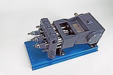
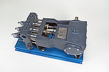
The NOV 12-P-160 Mud Pumps includes (3) Three New National 12-P-160 Triplex Mud Pumps 1600 HP, 7-1/4″ bore x 12″ stroke, single acting. 5000 PSI fluid ends. 1600 HP Bare Mud Pumps are currently configured for Offshore Service. The NOV 12-P-160 Mud Pumps are located in Houston and ready to be unitized for service.
Forged Steel crankshaft, Individual forged steel two piece interchangeable standard modules, 6-1/2” mission fluid king liners, Standard polyurethane valves and seats, Two piece fast change piston rods, Supreme pistons, Metal to metal liner retention, Clamp type liner and piston rod connections, Fast change valve covers standard, Piston liner lubricant spray system, Liner spray pump, Power end lube system with filter. Mounted on Integral two runner skid, Suction Manifold with vertical suction stabilizer, Suction line pressure relief valve, set for 70 PSI
Includes: motor supports, motor frame, tensioning screws, 2 V-belt guards, 2 pump Sheaves, 2 motor sheaves, banded V-belts, Holes to be drilled to accept EDM D79 Or GE-752 Traction Motors
National Oilwell Varco (NOV) is an American multinational corporation based in Houston, Texas. It is a leading worldwide provider of equipment and components used in oil and gas drilling and production operations, oilfield services, and supply chain integration services to the upstream oil and gas industry. The company conducts operations in more than 600 locations across six continents, operating through three reporting segments: Rig Technologies, Wellbore Technologies, and Completion & Production Solutions. National Oilwell’s two main predecessors, Oilwell Supply and National Supply, were founded in 1862 and 1893, respectively. These two companies manufactured and distributed pumps and derricks.
AfghanistanAlbaniaAlgeriaAmerican SamoaAndorraAngolaAnguillaAntarcticaAntigua and BarbudaArgentinaArmeniaArubaAustraliaAustriaAzerbaijanBahamasBahrainBangladeshBarbadosBelarusBelgiumBelizeBeninBermudaBhutanBoliviaBonaire, Sint Eustatius and SabaBosnia and HerzegovinaBotswanaBouvet IslandBrazilBritish Indian Ocean TerritoryBrunei DarussalamBulgariaBurkina FasoBurundiCabo VerdeCambodiaCameroonCanadaCayman IslandsCentral African RepublicChadChileChinaChristmas IslandCocos IslandsColombiaComorosCongoCongo, Democratic Republic of theCook IslandsCosta RicaCroatiaCubaCuraçaoCyprusCzechiaCôte d"IvoireDenmarkDjiboutiDominicaDominican RepublicEcuadorEgyptEl SalvadorEquatorial GuineaEritreaEstoniaEswatiniEthiopiaFalkland IslandsFaroe IslandsFijiFinlandFranceFrench GuianaFrench PolynesiaFrench Southern TerritoriesGabonGambiaGeorgiaGermanyGhanaGibraltarGreeceGreenlandGrenadaGuadeloupeGuamGuatemalaGuernseyGuineaGuinea-BissauGuyanaHaitiHeard Island and McDonald IslandsHoly SeeHondurasHong KongHungaryIcelandIndiaIndonesiaIranIraqIrelandIsle of ManIsraelItalyJamaicaJapanJerseyJordanKazakhstanKenyaKiribatiKorea, Democratic People"s Republic ofKorea, Republic ofKuwaitKyrgyzstanLao People"s Democratic RepublicLatviaLebanonLesothoLiberiaLibyaLiechtensteinLithuaniaLuxembourgMacaoMadagascarMalawiMalaysiaMaldivesMaliMaltaMarshall IslandsMartiniqueMauritaniaMauritiusMayotteMexicoMicronesiaMoldovaMonacoMongoliaMontenegroMontserratMoroccoMozambiqueMyanmarNamibiaNauruNepalNetherlandsNew CaledoniaNew ZealandNicaraguaNigerNigeriaNiueNorfolk IslandNorth MacedoniaNorthern Mariana IslandsNorwayOmanPakistanPalauPalestine, State ofPanamaPapua New GuineaParaguayPeruPhilippinesPitcairnPolandPortugalPuerto RicoQatarRomaniaRussian FederationRwandaRéunionSaint BarthélemySaint Helena, Ascension and Tristan da CunhaSaint Kitts and NevisSaint LuciaSaint MartinSaint Pierre and MiquelonSaint Vincent and the GrenadinesSamoaSan MarinoSao Tome and PrincipeSaudi ArabiaSenegalSerbiaSeychellesSierra LeoneSingaporeSint MaartenSlovakiaSloveniaSolomon IslandsSomaliaSouth AfricaSouth Georgia and the South Sandwich IslandsSouth SudanSpainSri LankaSudanSurinameSvalbard and Jan MayenSwedenSwitzerlandSyria Arab RepublicTaiwanTajikistanTanzania, the United Republic ofThailandTimor-LesteTogoTokelauTongaTrinidad and TobagoTunisiaTurkmenistanTurks and Caicos IslandsTuvaluTürkiyeUS Minor Outlying IslandsUgandaUkraineUnited Arab EmiratesUnited KingdomUnited StatesUruguayUzbekistanVanuatuVenezuelaViet NamVirgin Islands, BritishVirgin Islands, U.S.Wallis and FutunaWestern SaharaYemenZambiaZimbabweÅland Islands
‘ancl then locked down to avoid the preset pressure changing.‘Upon builtin installation of the lube oif pump, as shown item 9 in Figure 13, the pump mast be

SCOPEThis specification covers the preservation and storage procedure for shipment of new-buildNOV Triplex Mud Pumps shipped from the manufacturing plant.This specification is intended to provide preservation of new-build NOV Triplex Mud Pumpsfor six (6) months from the shipment of the mud pump from the manufacturing facility. If apump is to be stored for a period of time exceeding six (6) months, additional precautionsshould be taken as outlined in this specification.National Oilwell Varco recommends that all pumps are inspected for any signs of corrosionand for proper preservation at a minimum every three (3) months for pumps stored outsideand every six (6) months for pumps stored indoors.Sub-tier: National Oilwell PS-3081
MANUFACTURING PLANT PRESERVATION PRIOR TO PAINTDrain all water and clean out liner wash tank. Remove drain plug in bottom of liner washpump and drain water then reinstall plug. Remove discharge flange from liner wash pumpand pour one (1) pint of inhibiting oil-based concentrate (Cortec VpCI 329 Vapor CorrosionInhibiting oil-based concentrate or equivalent) into liner wash pump. Rotate two (2)revolutions by hand to distribute the product. Re-install discharge flange.Drain all oil from pump power end sump and remove crosshead covers and inspectioncovers. Clean out oil sump as per National Oilwell PS-3081 (Mud Pump Cleanliness).Spray all internal machined parts of power end and crosshead area with inhibiting oil-basedconcentrate (Cortec VpCI 329 Vapor Corrosion Inhibiting oil-based concentrate orequivalent). Rotate pump turn and re-spray. Pour quantity of inhibiting oil-basedconcentrate specified in the table below into power end sump.Mud Pump Models
For pumps equipped with chain drives, spray internal machined parts inside chain caseswith inhibiting oil-based concentrate (Cortec VpCI 329 Vapor Corrosion Inhibiting oil basedconcentrate or equivalent).
MANUFACTURING PLANT PRESERVATION AFTER PAINTRemove breather and pack with loose parts for later shipment with pump. Seal breatherhole with a greased solid plug. Affix a warning label near the breather opening (see Exhibit1).Spray all external unpainted machined parts of pump with rust preventative (CRC SP400 orequivalent).Cover large diameter pipe and other openings with hardboard and protective plastic wrap.Liner bushing openings shall also be covered and sealed.Seal all other pipe work (air, water, and electrical) with plastic caps of the correct size andstyle. Electrical J-boxes are to be encased in protective plastic wrap. Place two (2) onepound bags of desiccant inside each J-box before sealing with tape. Wrap pressuregauges with bubble paper and plastic.Tape or band down loose hinged guards and inspection covers.Spray all machined unpainted loose parts and expendables to be shipped with pump withrust preventative (CRC SP400 or equivalent). All parts will be wrapped or boxed to preventdamage.Affix one (1) warning label (see Exhibit 2) to the power end pump cover and one (1)warning label on the fluid end assembly of the pump. Affix warning labels on each loosepart container. In cases where the equipment will be boxed at an offsite export packer, asufficient number of warning labels will be supplied with the shipment.
STORAGE AT MANUFACTURING PLANT OR FINAL DESTINATIONIndoor storage is preferred whenever possible; but if outside storage is required, ensurepump is stored away from salt water spray, sand blast or other adverse conditions. It ishighly recommended that ship loose parts be stored indoors to eliminate conditions thatpromote condensation and direct sources of moisture.It is also recommended to store pump on blocks and cover entire pump with plasticsheeting.
PRESERVATION PROCEDURE WHEN STORAGE EXCEEDS SIX (6) MONTHS OFINITIAL PRESERVATION.Note: It is recommended that inspections be carried out on six (6) month cycles whenpumps are in indoors and three (3) month cycles when stored outside.Remove plastic sheeting.Remove side crosshead covers and top inspection covers and inspect for any internalcorrosion. Correct any adverse conditions.Replenish rust inhibitor to quantities previously listed.Rotate pinion shaft five (5) revolutions using supplied tool.Inspect for condition of external protection (rust preventative and paint).adverse conditions.
START-UP AFTER STORAGEAny pump that has been in storage will need a thorough inspection prior to start-up toinsure it has not been damaged in any way and that all parts are properly in place. Failureto observe the following points can result in serious damage. Before servicing the pump,the power end sump and chain drives housings will need to be drained of any inhibitingadditive. The Cortec brand products used for preservation are compatible with alllubricating oils and need not be totally removed when putting equipment into service.To service the Power End after storage and prior to start-up, remove all covers andthoroughly clean and inspect all of the parts and finished surfaces. Check all of thebearings to make certain they are clean and in good condition. Fill the power end withclean EP oil of the proper viscosity to the proper level. Make sure oil is poured into the oildistribution trough and is worked into all of the bearings. Replace all covers and installbreather.To service the Fluid End after storage and prior to start-up, remove covers and thoroughlyclean and inspect inside of the fluid end cylinders. Properly install valves, pistons, linersand all other fluid end parts. Carefully tighten all bolts, nuts, studs and workingconnections to specified torque requirements.
Pre-Start Up Requirements.....................................................................................1. Power End..................................................................................................2. Main Electric Drive Motors3. Auxiliary A/C Motors.4. Instrumentation...........................................................................................5. Liner Wash System.....................................................................................6. Fluid End....................................................................................................7. Suction Dampener/Desurger.......................................................................8. Pulsation Dampener....................................................................................9. Pressure Gauge............................................................................................10. Reset Relief Valve.......................................................................................11. Discharge Strainer12. Mud Pump Drive Assembly.a. Belt Drive Unitsb. Chain Drive Units.
INITIAL STARTUP PROCEDURESGENERAL:The initial startup procedures are written to assist the operator in preparing the pump packages for normaloperation. The startup procedures are separated into two categories: Part I: Pre-Commissioning, and PartII: Commissioning Procedures. It is suggested that a copy of these pages be made for each pump to beused as a check-off sheet.
Reservoir Capacity: 100 US Gallons (379 Liters)Note: The rust preventative on the internal surfaces of the pump is oil-soluble and iscompatible with the lubricants recommended above. It is not necessary to flush and drainunless the preservative has become contaminated (water, sand etc.).b. Oil Filters:Assure that the oil filters in the power end reservoir and external oil pump system are clean.2. Main Electric Drive Motors:
Clean liner wash tank, if needed, and fill with fresh clean water.Ensure that supply hoses and spray nipples are installed correctly.Start pump and adjust regulating valve to maximum flow without splash onto the extensionrods.
NOTE: When charging the bladder, make sure that the mud pump suction line valve has beenclosed and that all pressure has been bled off of the suction manifold surrounding the suctiondesurger
If a dampener is used, charge dampener with a hand-operated air pump to 10 PSI (0.7 bar).Once pump operations have been started, check the operation of the suction dampener byinspecting the sight glass. Add or release air pressure through the Shraeder valve to keep thediaphragm between the midpoint and the bottom of the sight glass.
Check the installation and the setting.NO SHUT-OFF VALVE is to be between the pump discharge and the relief valve.Ensure that piping from the discharge port goes directly to the mud tank/pit and is securelytied down, with a minimum downward slope of 1/4 per foot.Ensure that piping has pressure rating equal to the relief valve highest setting.
Check the belt guards to ensure that belts will not drag on the guard.Check the belt tension as instructed in the maintenance section of the operations manual.Check the alignment of the drive motors.
Check the chain guards to ensure that the chains will not drag on the guard.Check the oil pump to ensure that the relief valve is installed on the suction side.Start the pump and ensure that the spray nozzles are spraying oil over the full width of the chain.Adjust the relief valve to 15-25 PSI output with the warm oil.
PART II. COMMISSIONING PROCEDURES:GENERAL:The power end and the fluid end have gone through rigorous tests prior to being shipped from themanufacturing site; therefore, the following recommendations for the commissioning test are madefor the purpose of checking the overall unitization functions, including instrumentation, and toassure that there are no problems which may have occurred during transportation and storage.Operation of the pump in parallel to check the SCR-Motor assignments and controls, volumetricdisplacement and mudline systems are at the option of the purchaser.A. PRE-COMMISSIONING CHECKS:Prior to starting the unitized pump package, review the previously outlined Pre-CommissioningRequirements in Part I.Check the discharge mudline to assure that all necessary valves are open. Ensure that the mud tanksare full of test fluid (mud/water) prior to startup.Make the desired assignment of the SCR-Motor Control System to the pump motors, and open thethrottle slightly. Check to ensure that charge pump and liner wash motors have started.If no immediate problems are encountered, slowly throttle the pump to approximately 60 SPM andcontinue operating the mud pump while making the following inspections to assure that all systemsare working properly:1) Power End Lubrication:Check oil pressure:
5) Visually inspect the mud pump drive assembly for any unusual conditions, i.e. loose bolts,vibration, noise, etc.6) Check the performance of the supercharging system:
Check the valve for proper relief setting. The valve should be set 10% above thepressure rating for the liner size being used.Refer to the nameplates on each side of the pump or the pump datasheet to obtain theoperating pressure for that particular size liner.
B. COMMISSIONING OPERATIONAL TEST:DURATION: EIGHT (8) HOURS TOTAL RUNNING TIME.The following are basic guidelines for conducting of an eight (8) hour operational test. The pump wastest run under pressure in the manufacturing plant but with different motors and drives.The discharge pressure can be regulated by temporarily installing an adjustable choke at some point inthe discharge line.NOTE: There can be short intervals of shut-down time to fix leaks, make adjustments, etc., withouthaving to restart the test program.1. LOWER PRESSURE TEST DURATION: TWO (2) HOURS:TIMESTARTSTOP0-500 PSI (0.34-34.5 bar)40 min. @ 40 SPM
C. INSPECTIONS/CHECK-OFFS DURING TEST PROGRAM:The overall performance of the unitized pump package should be continuously monitored during theeight hour test program. The following checks should be made and recorded each two hours ofoperation.START
PREFACEThis manual is provided for guidance of those who wish to install, repair, maintain, or adjust theNational Oilwell Varco equipment covered herein. This information has been prepared with abasic viewpoint to give accurate and concise data needed to perform minor adjustments as wellas major overhauls.This information is not elementary, as it is intended for operators and servicemen who are familiarwith drilling equipment in general. It is not intended, nor would it be possible in such limitedspace, to cover every possible condition which may be encountered. Always use good, soundmechanical practices and safety precautions.All specifications are in accordance with Engineering designs and should be adhered to in allrepairs. Operation and maintenance information on equipment other than National Oilwell Varcosis taken in part from the various manufacturers manuals. If the equipment manufacturers issuelater instructions, or in the event of conflict, the manufacturers information will take precedenceover that shown in this manual, unless specifically stated otherwise.Refer to the General Lubrication Bulletin for approved lubricants. If any discrepancy existsbetween the recommendations in this manual and the General Lubrication Bulletin, those in theLubrication Bulletin will take precedence.The manual sections follow logical divisions in major components, and cover all standardproduction unless otherwise specified. Specifications and components covered are for standardequipment current at the time this manual was approved for printing.National Oilwell Varco reserves the right to discontinue models at any time, or changespecifications or design of any model without notice and without incurring any obligation.
IN ORDER TO PREVENT PERSONAL INJURY during performance of any maintenanceor inspection procedures, this equipment must be shut down and not operating. Eachmotor and generator is equipped with a motor cutout switch. This switch should be IN,and the safety bar in place, when any maintenance or inspection procedures areperformed. Employ good mechanical practices when making maintenance repairs,adjustments, inspections, etc.
INSTALLATION OF NEW PUMPYour National Oilwell Varco pump has been completely assembled and test operated underpressure before being shipped to the field. Unless otherwise instructed, the lubrication isdrained from the power end and the expendable parts are removed from the fluid end.Before putting the pump into service, the following precautions and operations must beperformed or checked.In order to prevent personal injury during the performance of any maintenance orinspection procedures, this equipment MUST BE SHUT DOWN AND NOT OPERATING,and all safety devices on prime movers, drives, etc., MUST BE IN THE SAFE POSITION.
SETTING THE PUMPThe skids under the National Oilwell Varco pumps are suitable for most any type ofinstallation. It should be noted, however, that the box type construction of the power framehas high resistance to bending but relatively less resistance against twist. Therefore, thesupport under the pump must be level and adequate to support the weight and operatingforces exerted by the pump.
Land InstallationsIn land installations, a mat of 3 X 12 (76.20 mm x 304.8 mm) boards laid side crosswise tothe pump skids for the entire length, or at a minimum, at the points indicated in Fig. 2, isusually sufficient. The boards should be a few feet wider than the width of the pump skidrunners. Wet or marshy locations may require a more stable foundation.
Fig. 2Suitable means, such as National Oilwell Varco pump spacers as shown in Fig. 3, shouldbe used to keep the pump anchored and the drive in alignment. National Oilwell Varcomud pump spacers provide 8-1/2 (215.9mm) adjustment. Any desired length may beobtained by lengthening the standard pipe spacer, which is made of 3 (76.20mm) extrastrong pipe.Three types of attaching heads are available with this spacer:
2.1.1 Permanent InstallationsOn permanent installations such as barge, platform, structural base, or concrete slab,where pump skids are bolted down, it is essential that the skids be properly shimmed toprevent possibility of twisting or distorting the power frame. The pump skids must sit solidon all shim points with bolts loose.On barge installations, the pumpskids are generally bolted down toT-beams running parallel and in linewith the pump skids. Install shims atpoints shown in Figs. 2 and 4 andobserve caution of proper shimmingto prevent twist or distortion.The shims on all installations shouldextend the full width of the skidbeam flanges and have a minimumlength of 12 (305mm).On installations where the power unit or electric motor is mounted integrally with the pumpskids, the preferred installation would be to set the pump package on the T-beam skids andprovide retention blocks rather than bolts to hold it in place. This will allow the pump tofloat and minimize the transfer of barge deck or platform distortion into the frame.2.1.2 Installation of the DriveThe drive between the mud pumps and the power source, whether V-belts or multi-widthchains, should be installed with the greatest care to assure maximum operating life withminimum of unexpected or undesirable shutdowns due to drive failures.When installing the drive sheave or sprocket, make sure all grease or rust preventative isremoved from the shaft and the bore of the drive. Remove all burrs or rough spots from theshaft, key, and keyway. Fit key to the keyways in both the shaft and drive and install keyinto shaft keyway.Coat pinion shaft with a light coating of anti-seize compound or light oil and install the drivesheave or sprocket hub. Tighten hub bolts as indicated below:
Adjust V-belts for proper tension.Adjust the belt tension by moving the sheaves apart until all of the sag has just beeneliminated from the tight side of the belt and some of the belts on the slack side.Then increase the centers approximately (13mm) for each 100 (2540 mm)center distance. Example: On 150 (3810 mm) center, move pump an additional (19.5 mm).
DO NOT OBTAIN BELT TENSION BY PICKING UP END OF PUMP ANDALLOWING BELTS TO TIGHTEN UNDER WEIGHT OF PUMP AS END ISBEING LOWERED TO THE GROUND.2.1.2.2 Chain Drivesa.InstallationProper installation and maintenance of the sprocket and chain drives are essential ifgood service life is to be obtained. Since many factors, such as chain width, centerdistances, speeds, and loads must be considered when determining the allowabletolerance for sprocket alignment, no good rule of thumb can be applied. The chainalignment must simply be held as nearly perfect as possible. A more precisealignment can be made by stretching two steel wires (piano wire) along one face ofthe two sprockets, one above and one below the centerline, and moving one of thesprockets until the wires touch at four points. This will determine that the centerlinesof the drives are parallel and the faces of the sprockets are square.b.
Drive chain lubricationThe pump drive chain lubrication system on the majority of National Oilwell Varcopumps is an independent system having its own oil pump, reservoir, and drive. Fillchain case to the indicated level with a non-detergent oil as follows:Ambient temperature above 32F (0C) SAE-30Ambient temperature below 32F (0C) SAE-20For temperatures below 0F, consult a reputable lubrication dealer forrecommendations.REFER TO GENERAL LUBRICATION BULLETIN for approved lubricants andadditional specifications. If any discrepancy exists between the recommendations inthis manual and the General Lubrication Bullletin, those in the Lubrication Bulletinwill take precedence.Since this is an independent system, it will require the same maintenance or serviceattention employed on any other piece of machinery, including:- Daily check of oil level.- Daily check on condition of oil.- Frequent check on oil pressure. (5-15 psi) (.352 - 1.06 kg/cm)- Volume of oil being applied to chain.- Condition of nozzles in spray tube.- Condition of oil pump drive (V-belts or chain)
NOTE: Oil pressure may be adjusted with the pressure relief adjusting screwon the rear of the pump housing. Pressure drops may also indicatesuction and discharge filter screens need cleaning.3
SUCTION SYSTEM REQUIREMENTSIndividual installation conditions will dictate the design of the suction system. The suctionof the FD-series pumps must have a positive head (pressure) for satisfactory performance.The optimum suction manifold pressure is 20-30 psi (1.75-2 kg/cm) for maximumvolumetric efficiency and expendable parts life. This head pressure is best supplied by a 5x 6 centrifugal pump with 40 h.p. 1150 rpm electric motor. This type of drive requires adevice to automatically start and stop the centrifugal pump motor simultaneously with thetriplex pump. On DC electric powered rigs a signal can usually be supplied from the DCcontrol panel to energize a magnetic starter when the mud pump clutch air line will providea set of contacts for energizing the magnetic starter when clutch is engaged.The charging pump can also be belt driven from the triplex pinion shaft charging type ofdrive is not as efficient at slow speeds with viscous fluids.Under some conditions the FD-Series pumps may be operated without a charging pump,provided the fluid level in mud pits is higher than the top of the liners, fluid being pumped islow viscosity and suction line must be short, straight and of at least the same diameter assuction manifold inlet.The suction lines should be piped with valve arrangements so the charging pump can beby-passed so operation can be continued in event of charging pump failure or formaintenance. Operation without a charging pump can be improved by replacing thesuction valve springs with a weaker spring.Suction desurgers are a very effective aid for complete filling of the liners and dampeningpulsations in the suction line which results in a smoother flow in the discharge line. If yourpump is equipped with a suction desurger it must be pre-charged with compressed airbefore operations are begun. See suction desurger manual for charging instructions.
CautionDo not pipe the return line from the shear relief valve back into the suction system as arelief valve operation will cause a sudden pressure rise in the system vastly greater thanthe system pressure ratings, resulting in damage to manifold, suction desurger andcentrifugal pump.
PREPARATION OF POWER ENDYour National Oilwell Varco pump has been completely assembled and test operatedbefore being shipped to the field. Unless otherwise instructed, the lubrication is drainedfrom the power end, and the expendables are removed from the fluid end for storageprotection. Before operating the pump, the following must be performed or checked:
Power End LubricationBefore installing lubricant, open inspection door in cover and check oil reservoir forpossible accumulation of condensation, etc., and drain and flush by removing the pipeplugs on each side of the pump.Add the proper type and quantity of lubrication in the power end. Refer to the LubricationSection of this manual, or lubrication plate on pump frame for type and quantity required.Recheck oil level after pump has operated for a period of 15 minutes. Shut pump downand allow approximately five minutes for the oil level to equalize. Check at oil level gauge,Item 1, Fig. 1. It is usually necessary for a few more gallons of oil to be added due to acertain amount being retained in the crosshead area and frame cavities.
With reference to Figure 5, remove the diaphragm stuffing box and plate (1) and rotatepump so that crosshead is at the front of the stroke. Thoroughly clean the front of thecrosshead and the face of the crosshead extension rod. Insert alignment boss oncrosshead extension rod into the crosshead bore and tighten the retainer bolts (2) to thefollowing torque. Safety wire bolt heads.FD-50050-60 ft. lbs. (7-8 meter kgs)FD-800 80-100 ft. lbs. (11-14mkgs.)FD-1000 350-370 ft. lbs. (48-51 meter kgs) FD-1600 350-370 ft. lbs. (48-51mkgs.)Thoroughly clean face of power frame and diaphragm stuffing box plate at Position A.Install gasket (3) and capscrews (10). Tighten capscrews as follows:FD-500 12-14 ft. lbs.(1.7 - 1.9 meter kgs)
Two types of piston and liner cooling systems have been used on National Oilwell VarcoFD-Series Pumps -- the stationary spray type and a moving nozzle type. Ref. Fig. 6. Themanifold (1) for supplying cooling fluid to the piston and liner assemblies is identical on bothsystems. Cooling fluid from either a remote source such as a water line, or from a pumpand reservoir system unitized on the pump skids (Ref. Fig. 7) must be piped into themanifold at the connection located in the pump frame under the crosshead extension rodsection.CAUTION:
With reference to Fig. 7, maintain electric motor (1) and centrifugal pump (2) accordingto manufacturers specifications. Rotation of the pump should be clockwise whenviewed from the impeller end.Adjust regulating valve (3) to apply as much water as possible to the liners withoutsplashing back on the crosshead extension rods and diaphragm stuffing box plate. 10gallons per minute per liner is the preferred flow rate. If water is allowed to splash onthe crosshead extension rods, some of the water may work back into the power end tocontaminate the lubrication oil.
Liner Cage and Lower Valve GuideInstall rear liner seal (5) and push into position against liner shoulder. Slide liner cage (6)into fluid end, align one hole in the cage with lower valve pot bore. Set lower valve guide(8) over valve stem through lower hole in cage with the wings on the guide turnedcrosswise to the pump. Press down on the guide, compressing the valve spring (7) untilthe guide can be rotated turn and seat into place underneath the cage. Insert the lowervalve guide locking clip (9) through the pad eyes on the lower valve guide and rotate clip tothe right to lock the valve guide tight against the OD of the liner cage. It may sometimes benecessary to put more or less bend in the center of the clip to make it retain the guidetightly while the clip handle snaps into position on the right hand side.
Cylinder headInsert the outer seal (5) in the fluid end bore against the liner cage. Slide the cylinder headplug (10) into fluid end. Apply a liberal coat of grease to both mating thread surfaces of thecylinder head (2). Screw cylinder head in and tighten with wrench furnished with pump andsledge hammer.Fluid leakage through the weep hole will indicate a defective seal or loose cylinder head.DO NOT plug weep holes as this can result in severe damage to cylinder head threads,thread rings, etc., in event of a liner seal failure.
Figure 9BA cross section through the fluid end is shown in fig. 9B. With reference to fig. 9Bthoroughly clean and assemble the fluid end parts in the following manner:Note: All of the parts in this fluid end assembly are designed with metal to metal seatingto alleviate friction wear from breathing action encountered in modern highpressure pump operation. For this reason it is essential that all parts be cleanand free of rust, nicks and burrs before being assembled.
LinerInstall wear plate seal (1) in counterbore of fluid end. Slide wear plate (2) over studs until itseats against fluid end. Slide liner thread ring (3) over studs with the starting thread at the5 oclock position and tighten nuts to 470-510 ft. lbs. (65-70 m/kgs.) torque.Note: Placing the starting thread at 5 oclock position makes engaging the liner lockthreads much easier.Place liner seal (4) in counterbore of wear plate. Apply thin coat of grease to ID of linerlock (5) and slide over rear of liner (6). Install two-piece liner lock ring (7) in liner grooveand O ring to hold them in position.Slide liner handling tool over liner up against liner lock ring and tighten set screw to secureit in place. Hoist liner assembly into position with jib hoist.Note: FD pumps are factory equipped with jib booms and liner handling tools. If olderpumps are converted to FD fluid ends a jib boom should be added to the pumpframe as considerable weight is involved in handling the liner assembly.Apply liberal coat of grease to liner lock threads. Align the starting thread of the liner lock(5) to the 7 oclock position and insert the liner into the liner thread ring (3) screw liner lockin until liner seats in position . Tighten with sledge hammer on hammer lugs.
Suction FlangeThe suction flange has a 12 (305mm) standard pipe thread connection and is custommade to match the companion flange on the pump suction manifold. The flange connectionis sealed off by an O-ring seal (14 OD x 13-1/2 ID x ), (356mm OD x 343mm I.D. x6.35mm Dia.)NOTE: Thoroughly clean O-ring groove and face of flanges before making up connection.Flanges must make up metal to metal to insure proper seal. Tighten flange bolts to 360490 ft. lbs. (50-68 meter kgs.) torque.CAUTION: If suction pipe is welded to suction flange, remove O-ring prior to welding.
Accessory ManifoldFig. 10 is not the standarddischarge arrangement on themodel FD-1600 pump, which usesthe strainer cross configuration.An accessory manifold, Fig.10, isavailable for installation on thedischarge manifold opposite thedischarge end. The manifold willaccommodate a dischargepulsation dampener (1) andprovides two 3-6000 PSI*sideoutlet connections for such items asa pressure gauge (2) and a shearrelief valve (3).When manifold is used, install andmaintain as follows:
The flange on the accessory manifold is a 5-1500 *RTJ. Thoroughly clean ring jointgroove, install ring (4) and tighten the flange bolts (5) to 1200 ft. lbs. torque. To assureuniform make-up of the ring joint connection, tighten the nuts in a criss-cross order.The shear relief valve (3) is installed on the discharge manifold for the purpose ofprotecting the pump from excessively high pressure overloads.The relief valve must be installed so that it will be directly exposed to the mud. DO NOTPUT ANY TYPE OF SHUT OFF VALVE between the relief valve and the manifold. Pipethe discharge side of the relief valve directly into the mud pit with as few turns in the line aspossible. IT IS NOT RECOMMENDED for the discharge side of the valve to be piped intothe suction line of the pump.* 5 -
3 - 6000 PSI = two 76.2mm - 422 kg/cmThe relief valve setting should be just above the maximum pressure rating of the particularliner size being used. CHANGE SETTINGS with each liner size change. DO NOT USEALLEN WRENCHES, WELDING RODS, or material other than that called for by themanufacturer of the relief valve, as this will affect the rating of the relief valve.The mounting for the dischage pulsation dampener (1) is a RTJ flange with R-39 ringgasket. Before installing dampener, thoroughly clean ring groove and ring, and after settingdampener into place, tighten the 1-1/4*nut (6) to 750 ft.lbs*. torque. To insure uniformmake-up, tighten nuts in a criss-cross order.Precharge dampener before starting up pump. Precharge pressure should not be morethan 2/3 of the pump discharge pressure, or a maximum of 650 PSI. (46 kg/cm)CAUTION: USE ONLY COMPRESSED NITROGEN OR AIR. DO NOT CHARGE WITHOXYGEN.* 1-1/4 = 32mm750 ft. lbs. = 104 meter kgs9
LUBRICATIONProper lubrication of the moving parts in any piece of machinery is the most importantsingle factor affecting its ultimate life. To obtain maximum trouble-free service life from thepower end of the National Oilwell Varco pump, it is necessary to perform routinemaintenance care and inspections to insure the proper amount of CLEAN lubricant is beingprovided.
The FD-Series pumps utilize the controlled flow oil bath splash and pressure system tolubricate the entire power end. The type of pressure system provided in each individualpump will govern the minimum SPM at which the pump can be operated, i.e. pumps whichhave pressure lubrication only to the main and pinion bearings, have a minimum ratedspeed of 40 SPM. Pumps in which pressure lubrication is provided to the main, pinion, andcrosshead bearings and crosshead compartments may be operated at a minimum speed of25 SPM, provided there is a minimum of 5 PSI oil pressure. (352 grams/cm)9.1
Minimum Operating SpeedsThe minimum speed for all pumps is 40 SPM.CAUTION: The pressure lubricating system can be provided with an externally mounted oilpump driven through V-belts or electric AC motor; or an internally mounted oil pump drivenfrom the main gear. When an internally mounted oil pump is used, the direction of rotationof the pinion shaft must be as shown in Fig. 11.
Controlled Flow Splash SystemThe controlled flow splash lubrication system is the same for all FD-Series pumps,regardless of the type of oil pump drive provided for the pressure system. In the controlledflow splash system, the main gear picks oil up from the reservoir, and when the teeth meshwith the pinion, the oil is displaced into various troughs and compartments in the frame.With reference to Figure 13, the oil thrown into trough (7) is directed through the oil tube (8)to the two pinion bearings.Oil passage from the top of the crosshead guide compartment to the crosshead bearing isshown in Figure 12. Oil accumulates in the compartment over the crossheads. The oilruns through the nipple (6) into the crosshead retainer to the oil passages (5) and on to thecrosshead pin bearing. As noted, the duplicate set of passageways (5) in the crossheadpin permits the crosshead pins to be rotated without having to give attention to holealignment. This permits the installation of crosshead pins from either direction.
Total Pressure lubrication SystemThe total pressure lubrication system, incorporating the internally mounted oil pump for theFD-series pumps, is shown in Figure 13.
In this system, filtered oil is supplied to the pump through the suction filter (1) and isdischarged from the pump into the manifold block (2). Oil is distributed from the manifoldblock to the pinion shaft bearing oil line (3) and spray nozzle (3A); and to the main bearingoil line (4) and the crosshead compartment manifold block (4A) located above thecrosshead compartment. The crosshead compartment manifold block (4A) distributes oil tothe crosshead, crosshead bearings, and extension rods. Pumps which do not have thecrosshead compartment manifold block (4A) do not have the total pressure lubricationsystem, and therefore have a minimum rated speed of 40 SPM.
A pressure gauge (5) is mounted on the back wall of the frame to show oil pressure beingmaintained in the manifold block. The oil pressure will, of course, vary with the speed ofthe main pump, however if a sudden pressure drop or increase occurs, refer to the sectionon maintenance of lubrication system for possible cause.A pressure relief valve (6) is mounted to the manifold block to keep excess pressure formdamaging oil pump and drive. The relief valve is preset at 40 PSI and must not betampered with.NOTE: If specified, the oil pump for the pressure lubrication system can be independentlypowered by an electric motor or some other type of prime mover. When theindependently driven oil pump is used, some type of alarm device or powerinterlock must be installed to assure the oil pump is operating when the main pumpis put into service.When installing the internally mounted oil pump (9, Fig. 13), position pump so that the backface of the drive gear is flush and parallel with the edge of the main gear, and gear teethhave*.010-.015 backlash. Remove inspection plate on power end cover for access to theinternally mounted oil pump and filter screen. (* .25 - .38mm)
A typical layout for the pinion shaft driven oil pump is shown in Fig. 14. The oil pump (1) ispiped into the oil system through the suction and pressure connections on the bottominside wall of the power frame. Ref. Item 10, Fig. 13. The V-belt drive (2) is adjusted bymoving pump up or down on the mounting bracket.Adjust the V-belt drive (2) to a point where the two halves of the belt can almost bepinched together between the thumb and fingers at the center of the drive.Overtightening can cause premature failure of the pump.When link type belting is used, caution should be exercised in predetermining beltelongation. Link type belting in A, B and C widths will elongate approximately 1 per foot(25mm per 305mm). When installing a drive, subtract 1 per foot from actual requiredlength (132 required - install 121) and stretch to fit. (Subtract 25mm/305mm)To prevent possible injury, always install guard (3, Fig. 14) over V-belts before puttingpump into service.10
MAINTENANCE OF THE LUBRICATION SYSTEMAdequate lubrication of the moving parts is, as stated, the most important single factoraffecting the ultimate service life of the pump. CARE AND MAINTENANCE of the systemis the sole responsibility of the operator or crew to which it has been assigned, and theextent to which this is applied will determine the amount of trouble-free service life that willbe obtained.The lubricant recommendations shown below, on the name plate on the side of the pump,or in the General Lubrication Bulletin included with this manual, are the result of extensivefield tests. Substitutions should be made only in extreme emergencies.REFER TO GENERAL LUBRICATION BULLETIN for approved lubricants and additionalspecifications. If any discrepancy exists between the recommendations in this manual andthe General Lubrication Bulletin, those in the Lubrication Bulletin will take precedence.Lubrication Specifications:Use extreme pressure, non-corrosive, anti-foaming gear lubricant as follows:Temperatures +30F to 155F (-1C to 68C) AGMA No. 6 EPTemperatures0F to 85F (-18C to 33C) AGMA No. 4 EP(Consult lubrication manual)Oil reservoir capacity:FD-500FD-1000
ONCE EACH TOUR, check and maintain oil level at the FULL mark on the bayonet gauge.PUMP MUST BE SHUT DOWN and allowed to stand idle for approximately five minutes toallow oil level to equalize.ONCE EACH SIX MONTHS, or more often if oil becomes contaminated with abrasiveparticles or corrosive compounds, drain and flush the oil reservoir and refill with newlubricant. Oil drains are located on either side of the pump frame.During the flushing procedure, thoroughly clean the oil troughs and the compartment in topof the crosshead guide. Also clean or replace the filter element in the air breather cap andclean suction screen. Remove covers from settling chamber and purge out contaminantsbefore adding new oil.Routine inspection on condition of oil should be made as condensation of moisture in theair, intrusion of mud, water or dirt, can necessitate a more frequent oil change.A settling chamber is located in the forward area of the power end floor. Contamination inthe oil splashed into this area is allowed to settle out and should be drained out of the pumpthrough the clean out covers located on the frame wall underneath the crossheadinspection doors.Once each month, remove clean out covers on both sides of pump to drain contaminatedoil from settling chamber. Approximately 15-gallons of oil will be lost; replenish the mainreservoir to compensate for the amount drained out.Once each week, remove one of the lower capscrews that secure the clean out cover tothe frame to drain off water condensate.ONCE EACH TOUR, check oil level in main reservoir. Maintain at full mark on dipstick tothe manifold block. If loss of pressure occurs, check for:- Clogged suction screen- Low oil level- Slipping V-belt drive- Broken or loose connections- Damaged or worn oil pump- Defective Relief ValveFor an abnormal increase in oil pressure, check for:- Plugged oil lines- Contamination causing oil to be viscous- Relief valve inoperative- Defective gauge- Other conditionswww.nov.com
Power EndRoutine inspection of the power end is the most important form of preventive maintenanceand will result in considerable savings by detecting any major trouble that might bedeveloping and allowing the necessary repairs to be made on a planned or normal rig-downtime.1. Check tightness of the main bearing bolts. Bolts must be tightened to the followingtorque:FD-500FD-1000
2. Safety wires Check safety wires on all bolts including the main bearing hold-down bolts, eccentricbearing retainer bolts, and gear retainer bolts. Replace any broken wires afterretightening the bolts. Refer to crankshaft assembly section for bolt torquerequirements.3. Oil lines Check all oil lines to insure they are intact and free of obstructions. Check oil pumpsuction hose for damage or flat areas.4. Suction filter Check condition of suction filter. Clean and replace as required.5. Main bearing cover Remove the main bearing cover and check tightness of main bearing retainer bolts,condition of the bearing rollers, etc. Clean and remove any sludge or foreign substancethat might have accumulated at the bottom of the bearing area.6. Main gear and pinion teeth Inspect the condition of the main gear teeth and pinion gear teeth for any indications ofabnormal wear. During the initial break-in period there will be some pitting on the faceof the gear teeth. This is referred to as initial pitting and is not harmful to the life of thegear. However, if routine inspection indicates the degree of pitting continues toincrease, immediately contact the local representative of the pump manufacturer for amore thorough inspection of the gear.www.nov.com
FD-1000 165-175 ft. lbs. (23 - 24 meter kgs)FD-1600 165-175 ft. lbs. (23 - 24 meter kgs)DO NOT EXCEED THESE VALUES. USE TORQUE WRENCHIf the crosshead or guide shows abnormal wear or scoring, replace immediately as themetal particles can cause damage to the bearings, etc. Excess wear can also causerapid wear to the piston and liners.8. Oil and oil reservoir Check condition of the oil and cleanliness of the oil reservoir. Service oil system asdescribed in the Lubrication Section of this manual.11.2
Roller BearingsAlthough the basic construction of the various sizes of National Oilwell Varco pumps variessomewhat, they all have one very important detail in common -- roller bearings. A rollerbearing is a precisely built machine within itself; therefore, careful handling is required inorder to obtain the long service life and high load carrying characteristics associated withanti-friction bearings.The main bearings are self-aligning spherical roller bearings. The pinion shaft is mountedon straight roller bearings. The eccentric bearings are straight roller with thrust plates oneach side to keep the eccentric straps in line, and the crosshead pin bearings are straightneedle roller bearings.None of the bearings require special adjustments.All inner and outer races are assembled by means of very accurate fits. This accuracy isnecessary; therefore, if the bearings are to be used again, the inner and outer races andthe roller assemblies of each bearing must be kept together, and reinstalled exactly as theycame off.
The running clearances of the bearings are predetermined by their precision fit to the shaftand the bearing carrier. When performing maintenance or overhaul, make sure the fitsshown in Chart I are obtained.When installing the pinion shaft assembly in the pump, observe the following precautions:a. Insure pinion bearing carrier gasket (1) and oil seal carrier gasket (2) are in placeand in good condition.b. The pinion bearing carrier (3) and the oil seal carrier (4) have the word TOP cast inthe face of the flange. MAKE SURE THE CARRIERS ARE INSTALLED WITH THISMARK AT THE TOP to correctly position oil troughs and align drain holes.c. Remove burrs, dents or gouges from the OD of the oil seal spacer (5) before slidingoil seal carrier (4) into place. Exercise care when sliding lip of seal over end of shaftto prevent it from being damaged by the sharp edge of the keyway. Also payparticular attention to insure oil seal lip IS NOT TURNED UNDER by edge of spacerwhen sliding seal onto the spacer.d. Tighten pinion bearing carrier bolts (6) to the approximate torque shown below:FD-500 100-125 ft. lbs. (14-17 m/kgs.)FD-1000 80-160 ft. lbs. (11-22 m/kgs.)
Crankshaft Assembly (Fig. 16)The crankshaft assembly consists of the crankshaft, eccentric ring gear, eccentric strapwith bearings, and the main bearings.The running clearances of the bearings are predetermined by their precision fit to the shaftand their respective bores. When performing any maintenance or overhaul, make sure thefits shown in Chart II are obtained.
Set crankshaft on a set of rollers (at main bearing position) and check runout on face ofgear with a dial indicator. If total indicator runout exceeds .006, remove gear anddetermine cause of misalignment. (.15mm)NOTE: If runout on face of gear is checked while crankshaft is mounted in the pumpframe, the running clearance in main bearings will require that a simultaneous set of dialindicator readings be taken at the end of the shaft and the face of the gear; the actualface runout at any point being the difference between these readings.b. Install the outer races of the eccentric bearings (13) and the outer race retainer ring (3)in the three eccentric straps. Outer race retainer ring must be positioned so that oilscoop is at the bottom when pump is at mid-stroke. Tighten retainer bolts (4) to thefollowing torque; safety wire heads.FD-500FD-1000
NOTE: Even though the main bearing carriers (10 RH and 11 LH) have differentconfigurations on the OD, they are interchangeable and will fit into the pump frame oneither side. The purpose of the shoulders on the OD of one of the carriers is to locateand retain the crankshaft in its respective position in the frame.www.nov.com
Installing Crankshaft Assembly in FrameIn order to obtain a more precise fit between the main bearing housing and the frame boreon F-Series pumps, the installation procedures outlined below are to be followed: (Refer toFig. 17)1. Place piece of wood between eye of eccentric strap and crosshead guide (as shown inFig. 18) to protect guide from scoring or gouging as the straps are sliding into position.2. Rotate the main bearing carrier so that the two flat spots (180 apart) are parallel withthe main bearing bolt holes, and slowly lower the crankshaft into position. (The flat spotprovides clearance for the main bearing bolts.)3. After placing crankshaft in the frame, and before installing the main bearing caps, checkthe rollers in the main bearings to assure that each row of rollers in each bearing isequally loaded. Equal loading is obtained by positioning the floating bearing carrier sothat the same number of inner and outer rollers supporting the weight of the crankshaftin each bearing are tight. Because of tolerances, etc., the total number of tight rollerscould vary slightly between individual bearings.4. Install and shim main bearing caps to obtain .003 (.076 mm) clamp or preload on themain bearing carrier. This preload is obtained by placing the correct amount of shimsunder the main bearing cap. The required amount of shims is determined as follows:
Installation of Crosshead GuidesWhen installing crosshead guides observe the following procedures and precautions:1. Thoroughly clean all dirt or contamination and remove all burrs or rough edges fromboth sides of the guides and the frame bore where the guides fit.2. If old guides are to be reused, inspect the wearing surfaces for wear and scoringstreaks. Pumps with serial numbers below those shown have identical upper and lowercrosshead guides which may be reversed to provide a smooth surface for the lowerguide. Worn guides may be used at the top as forces on the crosshead are alwaysdownward.
Installation of CrossheadsThe crossheads in the pumps can be installed through the front (fluid end) or back end ofthe crosshead guide. Reference Fig. 19. When installing crossheads, observe the followingprecautions:
3. Install the left hand crosshead first. Rotate eccentric assembly to move eye intocenter crosshead and right hand eccentric strap eye back, affording clearance toinstall center pin through right hand crosshead inspection door. Remove diaphragmstuffing box plate (1, Fig. 19) and install right hand crosshead through this bore. Slideinto place and install crosshead pin.* NOTE: If old crossheads are to be reused, inspect the sliding surfaces for wear orscoring. If necessary, the crossheads may be switched to opposite sides of thepump and rotated 180 to provide a smooth surface for the bottom of thecrosshead. The center crosshead can be rotated 180 and the crosshead pininstalled from the opposite side of pump.Slide crosshead pin into bore but do not seat on taper until the crosshead pin retainer(2) has been installed.4. Install crosshead pin retainer (2) and retainer bolts (3) and rotate pin until the fourcrosshead retainer to crosshead bolt holes (4) are in alignment. Install the crossheadretainer to crosshead bolts (4) and make up hand tight.Referring back to fig.12, page B-2, crosshead pin (4) can be installed without regard tooil holes (5). Two holes are provided so the pin can be rotated 180 in relation to pin toretainer plate screws (3).Seat crosshead pin in tapered bore by bumping large end with a light blow. Tightenretainer bolts (3 and 4, Fig. 19) to the following torque and safety wire:FD-500FD-1000
DO NOT EXCEED THESE VALUES. USE TORQUE WRENCH.NOTE: To pull the crosshead pin, remove the four crosshead retainer to crossheadbolts (4) and screw two of the bolts into the jack screw holes (5). Tighten the two jackscrew bolts until the pin breaks loose. Complete removal of the crosshead pin retainerplate (2) and slide pin out of bore.5. Check running clearance of crosshead by sliding long feeler gauges between top ofcrosshead and crosshead guide bore.The clearance should not be less than .020 (


 8613371530291