
mud pump maintenance manual for sale

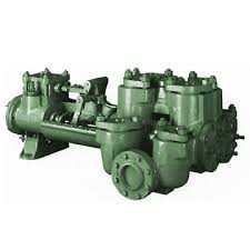
We stock fluid end parts for the5×6 mud pump, 5×6-1/4 FM45 mud pump, 5×8 mud pump, 5-1/2×8 mud pump, 5X10 mud pump, 4-1/2×5 mud pump, 7-1/2×8 mud pump, and 7-1/2X10 mud pump. The Gardner Denver mud pump model numbers for the above pumps are as follows: 5X6-FGFXG, 5X8-FDFXX, 5-1/2X8-FDFXX, 5X10-FDFXD, 4-1/2X5-FFFXF, 7-1/2X8-FYFXX, 7-1/2X10-FYFXD. We also handle Wheatley, Gaso, Worthington, Failing and Centerline parts and pumps. We also stock Foot Valve, Liner Puller, Valve Seat Puller, (4″ Inline Check Valve. Our Gardner Denver mud pump parts are not only competitively priced, they are also made in the USA. Oil Recommended by Gardner Denver. Call any of our experienced representatives to get the help and knowledge you deserve.

Our Premium Series liners feature bi-metallic construction utilizing a steel outer shell with an industrial chrome insert. Along with proper maintenance, can provide up to 800+ hours of service.
The NOV 12-P-160 Mud Pumps includes (3) Three New National 12-P-160 Triplex Mud Pumps 1600 HP, 7-1/4″ bore x 12″ stroke, single acting. 5000 PSI fluid ends. 1600 HP Bare Mud Pumps are currently configured for Offshore Service. The NOV 12-P-160 Mud Pumps are located in Houston and ready to be unitized for service.
Forged Steel crankshaft, Individual forged steel two piece interchangeable standard modules, 6-1/2” mission fluid king liners, Standard polyurethane valves and seats, Two piece fast change piston rods, Supreme pistons, Metal to metal liner retention, Clamp type liner and piston rod connections, Fast change valve covers standard, Piston liner lubricant spray system, Liner spray pump, Power end lube system with filter. Mounted on Integral two runner skid, Suction Manifold with vertical suction stabilizer, Suction line pressure relief valve, set for 70 PSI
Includes: motor supports, motor frame, tensioning screws, 2 V-belt guards, 2 pump Sheaves, 2 motor sheaves, banded V-belts, Holes to be drilled to accept EDM D79 Or GE-752 Traction Motors
National Oilwell Varco (NOV) is an American multinational corporation based in Houston, Texas. It is a leading worldwide provider of equipment and components used in oil and gas drilling and production operations, oilfield services, and supply chain integration services to the upstream oil and gas industry. The company conducts operations in more than 600 locations across six continents, operating through three reporting segments: Rig Technologies, Wellbore Technologies, and Completion & Production Solutions. National Oilwell’s two main predecessors, Oilwell Supply and National Supply, were founded in 1862 and 1893, respectively. These two companies manufactured and distributed pumps and derricks.
4 Use of new pump ................................................................................................................................74.1 Installation of new pump..............................................................................................................................74.2 Requirement to suction system...................................................................................................................114.3 Preparation of power end ...........................................................................................................................114.4 Spray system ..............................................................................................................................................134.5 Checkup in fluid end ..................................................................................................................................15
5 Lubrication .......................................................................................................................................195.1 Minimum operating speed..........................................................................................................................195.2 Flow-controlled splash lubrication system.................................................................................................195.3 Pressure lubrication system ........................................................................................................................205.4 Maintenance of lubrication system.............................................................................................................24
6 Maintenance and Assembling of Main Components.....................................................................256.1 Power end...................................................................................................................................................256.2 Rolling bearing...........................................................................................................................................276.3 Pinion shaft assembly.................................................................................................................................286.4 Crankshaft assembly ..................................................................................................................................296.5 Installing crankshaft assembly in frame .....................................................................................................316.6 Installation of crosshead guide ...................................................................................................................336.7 Installation of crosshead.............................................................................................................................336.8 Check crosshead alignment........................................................................................................................356.9 Maintenance of fluid end............................................................................................................................366.10 Welding and repair ...................................................................................................................................416.11 Replacing air bladder of dampener...........................................................................................................43
7 Information in Maintenance Work.................................................................................................447.1 Daily maintenance work.............................................................................................................................447.2 Weekly maintenance work .........................................................................................................................447.3 Monthly maintenance work........................................................................................................................457.4 Yearly maintenance ....................................................................................................................................457.5 Other precautions in maintenance ..............................................................................................................46
9 Attentions in Preservation ...............................................................................................................4710 Attentions in ordering....................................................................................................................4711 Special tools list delivered with HHF-1000 drilling pump ..........................................................4812 Spare parts list delivered with HHF-1000 drilling pump ...........................................................4913 Recommended spare parts list (HHF-1000 drilling pump) ........................................................50 OPERATION MANUAL OF HHF-1000 DRILLING PUMP
HHF-1000 drilling pump is one of the most important equipments for drilling rig. The parts andcomponents of this drilling pump are designed and manufactured according to API 7K and relatedstands. It can satisfy the drilling operation requirements of drilling rig. For the purpose of making user effectively operate and maintain the drilling pump, we havecompiled this “User’s Manual for HHF-1000 Drilling Pump”. This manual generally describes in detailthe performance parameters, configuration and function, installation and adjustment, operation andmaintenance, frequent failure and troubleshooting, expendables replacement and other precautions etc.we do our best to ensure the listed data exact, the operating method simple and practical, convenient todrilling site operator and service personnel. At the rear portion, we provided the list of spare parts recommended for reference while users doreplacement parts ordering, if the requested parts exceed the range listed, consult the parts list anddrawings attached in manual.
1 Safety warnings1.1 The personnel who are occupied in installation, operation and maintenance of drilling pumps shouldbe trained and qualified, and carry out the work with qualification certificate.1.2 The main personnel who are engaged in installation, operation and maintenance of drilling pumpsshould be experienced in corresponding installation, operation and maintenance.1.3 There must be a chief principal for the installation, operation and maintenance and persons in chargeof each work, and detailed and reliable safety measures should be taken.1.4 All the persons on duty must put on safety wares according to the related regulations. And theperson who works high above the ground should wear safety belt well.1.5 All the equipments should be used strictly in accordance with their operating rules and related safetyregulations.
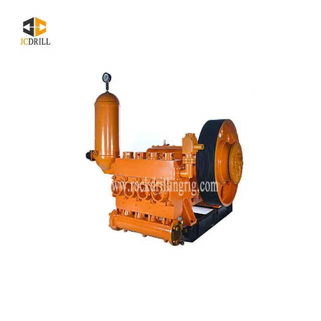
2 General HHF-1000 drilling pump is a kind of horizontal, triplex, single acting piston pump. It feeds andcirculates high-pressure drilling fluid, which flushes the wellbore bottom and crushes rocks, cools andlubricates drill- bits and carries the cuttings (rock chips) to the surface. The drilling pump mainly consists of two portion, power end and fluid end (see Fig. 1). The powerend includes the assemblies of frame, pinion shaft,crankshaft,crossheads etc. The fluid end includes theassembly of cylinder block (fluid end),valves, liner, piston, suction and discharge manifolds and so on.The parts and components of this pump are designed and manufactured according to API 7K. Allwearing parts at the fluid end such as cylinder liner, piston and valve assembly etc are universal andinterchangeable and can be replaced with the same type parts and components in conformity with theabove-said API 7K. To avoid ‘air lock’ and reduce outlet pressure fluctuation,a suction air damper anddischarge air damper are respectively installed at the suction manifold and one side of dischargemanifold of pump. At the other side of manifold, a shear pin relief valve is installed to guarantee that thepump pressure will not excess the rated working pressure. Each pump is equipped with a charging pumpto ensure good suction performances for the pump while operating at high strokes. A combination of splash lubrication and forced lubrication is adopted to lubricate all gears,bearings and crossheads at the power end. The cylinder liners and pistons in the fluid end are lubricated,flushed and cooled by cooling fluid supplied from a spray pump.
No. Model HHF-1000 Horizontal, triplex-cylinder, single acting piston 1 Type pump 2 Rated input power 1000hp(746kW)
3.2 Performance parameters The performance parameters of HHF-1000 drilling pump are shown in the following table II.Table II Performance parameters for pump HHF-1000 Cylinder liner dia. and rated pressure 6-3/4″ 6-1/2″ 5-1/2″ 4-1/2″ 6″152mm 5″127mm 171mm 165mm 140mm 114mmStroke Rated 3000 20.7 4322 29.8 2370 16.3 2558 17.6 3572 24.6 5000 34.5 SPM power psi MPa psi MPa psi MPa psi MPa psi MPa psi MPa Displacement 1071 hp 697 GPM 646 GPM 551 GPM 463 GPM 382 GPM 310 GPM 150 799 kW 43.97 L/s 40.76 L/s 34.76 L/s 29.21 L/s 24.10 L/s 19.56 L/s 1000 hp ※ 651 GPM 603 GPM 514 GPM 432 GPM 357 GPM 289 GPM140 ※ 746 kW 41.07 L/s 38.04 L/s 32.43 L/s 27.25 L/s 22.52 L/s 18.23 L/s ※ 928 hp 604 GPM 560 GPM 477 GPM 401 GPM 331 GPM 269 GPM 130 692 kW 38.11 L/s 35.33 L/s 30.09 L/s 25.30 L/s 20.88 L/s 16.97 L/s 857 hp 558 GPM 517 GPM 441 GPM 370 GPM 306 GPM 248 GPM 120 639 kW 35.20 L/s 32.62 L/s 27.82 L/s 23.34 L/s 19.31 L/s 15.65 L/s 785 hp 511 GPM 474 GPM 404 GPM 339 GPM 280 GPM 227 GPM 110 585 kW 32.24 L/s 29.90 L/s 25.49 L/s 21.39 L/s 17.67 L/s 14.32 L/s 714 hp 465 GPM 431 GPM 367 GPM 309 GPM 255 GPM 207 GPM 100 532 kW 29.34 L/s 27.19L/s 23.15 L/s 19.49 L/s 16.09 L/s 13.06 L/s 642 hp 418 GPM 388 GPM 330 GPM 278 GPM 229 GPM 186 GPM 90 479 kW 26.37 L/s 24.48 L/s 20.82 L/s 17.54 L/s 14.45 L/s 11.73 L/s 4.65 GPM 4.31 GPM 3.67 GPM 3.09 GPM 2.55 GPM 2.07 GPM 1 0.2934 L/s 0.2719 L/s 0.2315 L/s 0.1949 L/s 0.1609 L/s 0.1306 L/s
4.1 Installation of new pump The HHF-1000 drilling pump manufactured by our company has been completely assembled andtest-operated under load and then drained all lube from power end before being delivered to ourcustomers. The pump must be checked and operated according to the following methods and measuresbefore being put into operation. In order to prevent personal injury during the performance of anychecking and maintenance work, it must be shut down, all safety and protection device installedon the prime mover and transmission device must be put in safe positions.
The skid under the HHF-1000 drilling pump is fit for all types of installations, but it is worth to bementioned that although the frame with box structure at the power end has high resistances to bending,but relatively has lower resistance against twist; therefore, the foundation under the frame must be leveland with enough strength to bear the pump’s dead load and dynamic forces exerted upon duringoperation.
In ground installation, it is suggested that a underlay with at least eight pieces of 3″×12″(76mm×305mm)boards be placed under the pump skids along the entire length,the positions asshown in the Figure 3. The foundation under the pump skids must, at least, be 12″(305mm)wider thanthe width of the pump skid runner. More solid foundations are required in case of the installation beinglocated in wet or marshy land.
While the drilling pump shall be permanently installed on the structural base or concretefoundation of a barge or drilling platform, and the pump skid shall be fastened by bolts, it is essentialthat the skid must be properly shimmed to prevent the power end frame from possible distortion or twist.The pump skid must be solidly sat down on all shims while all bolts are loose.
In case of barge installation, the pump skid is usually bolted to T-beam, the positions for installingshims are shown in the Figure 3 and 4. Properly shimming should be done to avoid possible twist ordistortion. All shims must exceed the full width of the skid beam flanges and have a minimum length of12” (305mm).
When integral installation for power unit or electric motor and pump skid are required, the pumpmust be fixed on the skid of the T-beam, with retention blocks rather than bolts; in this way, the drillingpump could be a bit “floating” so as to reduce greatly the possible deformation of the pump framecaused by the deformation of barge deck or platform.
Whether to use V-belts or multi-row chains or universal shaft for the power transmission betweenpower unit and drilling pump, installation precision should be ensured for the longest service life andminimizing the shut-down time caused by failures from the drive.
Tightening Force exerted on Pump model Hub Wrench Length torque wrench HHF-1000 W 813N.m 900mm 900N
Correct installation and maintenance are important means to extend the service life of chain driveand chains and sprockets themselves. Many factors such as the width of chain, center distance, speedand load etc. are to be considered when determining the allowable alignment tolerance of sprockets;since there is no perfect “operating method” to be applied, therefore, what we can do is to make thechain alignment as exact as possible. A more precise alignment can be made with two stretching steelwires (better for piano) along one side of the both sprockets; one is put above the centerline and anotherbelow the centerline, and then move one of two sprockets until the strings have touched 4 points of thesprocket rim, or the distances they reach to sprockets rim are not more than 0.079″(2mm) , in this way,to determine the two centerlines of sprockets are parallel and their end face are vertical to their shaftcenterline.
B. Lubrication of drive chain The lubrication system for chain drive of HHF-1000 pump is an independent system with its ownoil pump, oil tank and drive. Fill the chain box and reach marked level with lubrication oil as follows:
Refer to the general lubrication bulletin for approved lubricants and additional specifications, ifany difference exists between the recommendation in this manual and the general lubrication bulletin,those in bulletin will take precedence.
4.2 Requirement to suction system The design of suction system of drilling pump must consider separate installation. The suction ofHHF series pump must have a positive head (pressure) for satisfactory performance. The optimumpressure in suction manifold is 20~30psi(0.14~0.21MPa)for maximizing the volumetric efficiencyand wearing parts life. This positive head (pressure) can be supplied by a 5×6 centrifugal pump(matched with a 40HP, 1150RPM motor)or a above size pump . This type of suction system requiresto start and stop automatically the centrifugal pump and mud pump synchronously. In DC electric rig,generally, a signal can be supplied from DC control panel to actuate an electromagnetic starter.
The suction line arrangement shall be such that the charging pump can be bypassed. When thecharging pump faults or in servicing, the mud pump can work continuously. The operation without acharging pump can be improved by replacing the suction valve spring with a weaker one.
Note: do not connect the return line of shear relief valve to the suction line, because the reliefvalve actuating will cause a sudden pressure rise in suction system, while the pressure exceeds thesystem pressure rating, this may results damage of manifold, air damper and centrifugal pump.
4.3 Preparation of power end The HHF series drilling pump manufactured by our company has been completely assembled andtest operated, the lubrication oil has been drained from power end before being delivered to customer.Before putting into use, the following must be conducted or checked:
Before adding lubricant open the inspection door on cover and check for possible accumulation ofcondensation in oil sump, drain by removing the plug screw (No. 2 in figure 8) on both sides of mud
pump and flush the inner chamber, add proper type (trademark ) and quantity of lubricant in power endaccording to the requirements written in nameplate riveted on frame and check oil level.
Before starting, it is also need to open the cover on rear plate and the side cover of crosshead,add sufficient lube to bearing oil groove, crosshead oil groove, gear pair, friction pair of crossheadand lower guide, make all friction surfaces of power end to be properly lubricated. If the drillingpump adopted the electric oil pump built outside, it must be firstly started before starting thedrilling pump to get satisfactory lubrication performance.
Recheck the oil level after operating the mud pump about 15 minutes, stop pump and waiting about5 minute for oil level lower and quiet, check the oil level gauge (No. 1 in figure 8), about 10 liters oilmust be added generally, because of a certain amount of oil remained in crosshead and frame cavity.
As shown in figure 5, remove the stuffing box and baffle plate (1), and crank the mud pump tomake the crosshead at the front of stroke, check the bolts for tightness. If the cleanness degree betweencrosshead front and extension rod and the tightness of bolts not conform to requirements, remove thecrosshead extension rod, clean the front of crosshead and the face of extension rod thoroughly, insert thealignment boss on extension rod into the alignment bore on crosshead and tighten the fixing bolt (2) to350~370ft. lbs(475~500N.m), finally lock them with wire.
4.4 Spray pump system The spray system consists of spray pump assembly, water reservoir, spray tubes etc. It is used toflush, lubricate and cool the liner and piston while pump running.
The spray pump is a centrifugal pump, driven by pinion shaft via pulley (or driven with motorindependently), water is used as cooling lubricant. In all operating time the cooling fluid must besupplied sufficiently to piston and liner, stoppage of cooling fluid will result in instant damage of pistonrubber and liner.
The HHF-1000 drilling pump manufactured by our company adopts stationary spray tube as shown in figure 6, including holder (1) mounted on frame, pipe nipple(2)and spray tube(3), which spray
The cooling fluid is pumped to manifold on left (right) frame wall via spray pump(No. 3 in figure 8)from water tank(No. 5 in figure 8), adjust the ball valve (No. 4 in figure 8) to supply as much cooling water as possible to spray piston and liner but without splashing back on the crosshead extension rod and baffle plate, otherwise, a few water will penetrate stuffing box to pollute lubrication oil in power end.
1.to spray pump suction pipe 2.filter screen 3 3.drain hole, frame 4. sediment chamber 2 4 5.drainage port1 5 Fig. 7
4.5 Checkup in fluid end As mentioned above, the HHF series drilling pump manufactured by our company has beencompletely assembled and test operated before being delivered to customer, consider the possibledisassembly in transportation and various working condition, before putting in operation, the followingcheckup must be carried out:
Remove the three valve pot covers, three cylinder heads and cylinder head plugs, inspectrespectively the installing position of suction/ discharge valves and seats for correct installation, if theydo not conform requirements, and redo the assembly and adjustment according to requirements writtenin section “Maintenance of fluid end”. While the suction manifold and discharge manifold have beeninstalled well, feed the suction manifold and cylinder block (fluid end) with water or drilling fluid tobleed air completely, then install the valve pot covers and tighten them.
The discharge flange is one of 5 1/8″(127mm)5000psi. take down the flange and gasket ring, weldthe flange to discharge line (user conducts the welding himself) , tighten the connection bolts and nutsevenly in a criss-cross manner to 1200~1600ft.lbs(1625~2165N.m)torque. If the other end ofdischarge manifold is not connected to mud line, plug it with blind flange, tighten the connection boltsas described as above
The shear relief valve (3) is installed on the assistant manifold for the purpose of protecting thepump from pressure exceeded the rated value to guarantee safety of the mud pump. The shear reliefvalve must be installed so that it will be directly exposed to mud tanks; and no gate valves may beinstalled between the relief valve and the discharge line. Pipe the outlet of the relief valve directly to themud tank by seamless steel pipe and with as few turns in this line as possible. If a turn is necessary, theelbow bend should be > 120°. It is not allowed to pipe the outlet of the relief valve to the suction pipesof the pump.
Before starting drilling pump, precharge the pulsation dampener to no more than 2/3 of the pumpdischarge pressure, the maximum precharge pressure is 650psi(4.5MPa). The pulsation dampener shallbe precharged with nitrogen or air. Do not precharge with oxygen, hydrogen or other flammable andexplosive gas.
The charging will be conducted with a set of charging equipment (air damper charging hosesassembly) provided together with the pump, as shown in Figure 10, and the operation process are asfollows:
B. When servicing the dampener, its internal pressure must be zero, at the same time, thedrilling pump pressure must be zero also. Don’t judge the pressure with pressure gauge readingonly; you must open the discharge valve cap to release pressure. When the residual pressure is low,the pressure gauge will be no indication, but this low pressure may result accident still.
5.1 Minimum operating speed To lubricate whole power end, a combination of splash lubrication and pressure lubrication isadopted for HHF-1000 pumps. When a gear oil pump is driven mechanically (except driven by aelectric motor), the pressure system adopted, in fact, governs the minimum SPM of drilling pump. Asfor the pressure lubrication systems adopted for HHF-1000 pump, it can operate at a minimum SPM of25; at this time, the lowest oil pressure is 5 psi (0.035 Mpa).
Note: The pressure lubrication oil pump can be installed outside of drilling pump and driven byV-belt/ individual motor, or installed inside of drilling pump and driven by big gear ring. When the laterinstallation is adopted, the rotation direction of the pinion shaft shall be as shown in figure 11.
1.pinion shaft 2.big gear ring 3.oil pump gear
5.2 Flow-controlled splash lubrication system The flow-controlled splash lubrication system is regardless of the type of oil pump for lubricationof HHF-1000 pump. In the flow-controlled splash system, the big gear ring brings the oil up from thesump; and when it mesh with the pinion, the oil is squeezed out and splashed to various oil grooves andoil cavities in the frame. With reference to figure 13, the oil is thrown into the groove (7) and flowsthrough pipe (8), to the bearings on the two sides of the pinion shaft.
5.3 Pressure lubrication system The pressure lubrication system adopted for HHF-1000 drilling pump is equipped a lube oil pump,as shown in Figure 13; in this system, the oil is sucked in through the suction filter (1) and then throughthe connector block II (2), distributed to the pinion shaft nozzle (3A), main bearing oil-pipe (4) and theconnector block I (4A) for crosshead, again through the block I (4A) distribute oil to the crosshead,crosshead bearing and extension rod.
A pressure gauge (5) is installed on the back base plate of the frame to show the oil pressure in theconnector block II. It is obviously that the pressure reading changes with the speed of the pump.However, if a sudden pressure drop or increase occurs, the reasons must be found according to thesection on Maintenance of lubrication system.
A pressure relief valve (6) is installed on the connector block II (2) to prevent the pump and itsdrive from possible damage caused by excessive pressure. The relief valve is preset to 80 psi (0.55 MPa)and then locked up to avoid the preset pressure changing.
There are two modes of lubrication oil pump arrangement for option—“built-in” and “built-out”. Ifuser do not requested, ordinarily, we arrange them to “built-in” mode, no matter what mode adopted, theinternal lubrication piping are same.
When the lubrication oil pump is “built-in” installed (No. 9 in figure 13), the oil pump must belocated well, the oil pump gear shall be parallel to big gear ring of drilling pump and meshed properly,the backlash of gears shall be 0.0236″~0.0354″(0.60~0.90mm).。
Figure 14 is a typical mode for oil pump drive, the oil pump is driven by pinion shaft via V-belt,the oil pump(1) is connected to lubrication piping via connector block and tube. The V-belt (2) shouldnot be tensioned too much to prevent the premature damage of oil pump. To prevent personnel injury,the belt drive guard (No. 3 in figure 14) must be installed well.
Fig. 15 show the mode of oil pump driven with motor. The connection between lubrication oilpump and lubrication piping of drilling pump is basically same to former, before starting the drillingpump, the lubrication oil pump must be firstly started to make all movement parts sufficientlylubricated.
5.4 Maintenance of lubrication system Sufficient lubrication of all movement parts is the most important factor to extend the service lifeof the pump; to maintain carefully the lubrication system is the duty of operators. In fact, a good or poormaintenance of the lubrication system determines a long or short trouble-free service life of drillingpump.
The recommended lubrication oil are as follows; and also shown on nameplate fixed on the pumpframe. All data recommended are the results of long-period tests in the oil field; therefore, anysubstitution of lubrication oil could only be used for emergency conditions.
Every shift, check the oil level and maintain the level at the FULL position; in view of oil levelcompensation, it is allowed to run the mud pump for 5 minutes at a slow speed and make sure the oillevel at the stipulated position.
Check twice every 6-month, if the oil has any abrasive particles and corrosive compounds in it,drain all oil and flush the oil sump before filling new oil. The oil drains are located on side of the pumpframe. During flushing, thoroughly clean the oil grooves and the oil chamber above the crossheadguides, and also clean or replace the filter element of suction filter, and clean the suction filter screen.Before filling new oil remove the cover from settling chamber and clean out sediments.
6.1 Power end Routine checkup to power end is the most important work of preventive maintenance. It can findvarious troubles and eliminate them in time. This work can be done while the drilling operation stops orthe drilling rig moving.
6.2 Rolling bearing HHF series drilling pump adopt rolling bearings. The rolling bearings are precision mechanicalcomponents, must be carefully maintained in order to keep high load capacity and long service life. The main bearing for crankshaft is spherical aligning roller bearing; the pinion shaft adopts shortcylindrical roller bearing; the eccentric bearings are single row short cylindrical roller bearing with rib,convenient to assemble and disassembly; the crosshead pin bearings are double row long cylindricalroller bearings. The inner ring and outer ring of all bearings are very exactly machined, the movement clearance ofbearing is very small, need not to adjust specially after assembling. The bearing must be used andreplaced with a whole set. Even though only one part of a bearing is failure, the whole set of bearing(including inner ring, outer ring, roller and roller cage) must be replaced. If there is extra clearance,wearing in ring raceway, spot corrosion or shell off on rolling element appeared, this indicates bearingfailure, the bearing must be replaced as soon as possible. Assembling (installing) a rolling bearing to shaft, the heating assembly (shrinkage) method shouldbe adopted. The damaged bearing or inner ring need be removed from shaft, this can be done by strikewith copper rod and hammer, or gas cutting but take care to avoid damage to shaft. Generally, we adoptoil bath heating to install bearing, the heating temperature is controlled under 300℉(149℃). Oil andoil pan used for heating should be clean, the inner ring of bearing must be underlayed in oil pan whilefiring directly under oil pan, and the oil bath heating for bearing can not exceed 3 minutes commonly. It is not suitable to heat bearing with flame gun. In special case, it must be performed by salted gaswelder, and the flame must be at least 6″(150mm)away from bearing, and the heating temperature canbe tested by temperature testing gun. The overheating of bearing must be avoided, otherwise, thebearing shall be softened because of temper. Once the bearing is heated and installed on shaft, you should wait it to cool down naturally in place,don’t water it to speed cooling down. The quick cooling will result “heat crack” damage in inner ring,outer ring and rolling element. Don’t knock bearing with steel hammer, while installation, you can use wood hammer or copper
In the above table, T indicates interferences, L indicates clearances. The pinion is an integral part of the shaft. The running clearances of bearings are predeterminatedby their precision fits to the shaft and the bearing carrier. When performing maintenance or overhaul,the fits shown in table Ⅲ shall be obtained It is needed only to install the bearing inner ring and wearing sleeve (15° chamfer towards outside)
to the pinion shaft, the assembly of pinion shaft is now finished, and it can be installed to pump framefrom either side of frame assembly(see figure 16). When installing the pinion shaft into the frame assembly, observe the following precautions: A. Ensure the bearing carrier gasket(6)and end cover (oil seal carrier) gasket(5)are in place andin good condition. B. When installing the bearing carrier(7)and end cover(4), make sure the oil grooves arepositioned correctly at just down and aligned to drain hole. Besides, the oil collecting box on bearingcarrier must be positioned at just down. C. Remove burrs, nicks or groove on wearing sleeve(3), then install the end cover(4)in place.While installing, take care to prevent the oil seal lip from damage by the sharp edges of keyway, whenthe oil seal passing through wearing sleeve, don’t allow the oil seal lip turn on wearing sleeve. D. Tighten the bearing carrier bolt(12) to torque of 140~165ft.lbs (190~225 N.m). E. Check the inner and outer ring and rolling element of pinion shaft bearing for good condition. Ifthere is any wear and tear, galling, flaking, grooving, or the radial clearance exceeds 0.0079″~0.0118″(0.20~0.30mm), it is recommended to replace the whole set of bearing.
6.4 Crankshaft assembly The crankshaft assembly consists of the crankshaft, connecting rod (eccentric strap) and bearing,big gear ring, main bearing etc. The running clearances of bearings are predeterminated by theirprecision fits to the shaft and respective bores. When performing any maintenance or overhaul, makesure the fits shown in table IV shall be obtained. Table Ⅳ Description Position Value T0.00023″~T0.0047″ Main bearing inner ring to shaft journal A T0.060mm~T0.121mm 0″~L0.0043″ Main bearing outer ring to bearing carrier bore B 0mm~L0.108mm
6.6 Installation of crosshead guide 6.6.1 Thoroughly clean and remove dirty, burrs and rough edges from both sides of the crosshead guides and frame bores where the guides fit. 6.6.2 If you want to reuse old guide, check whether it is worn and scored or not, otherwise, replacewith new one. Note: For HHF-1000 drilling pump, the upper and lower guide is not interchangeable, theupper guide is made thinner than lower guide, its rear has bigger chamfer and has oil hole atmiddle part. 6.6.3 Install upper and lower guides, tighten the guide screw to torque 150~200ft. lbs (200 N.m~270N.m). 6.6.4 Check between frame and guide at point A (see figure 20, A) with 0.002″(0.05mm) feelergauge, to ensure guides fit into frame and no gap existed.
1 connecting rod 2 upper guide 3 wood block 4 lower guide 5 crosshead Fig. 19 6.7.1 Thoroughly clean all dirty, burrs and rough edges from the OD of crosshead, Id of crossheadguides and crosshead pin holes, wipe dry the taper pin hole so that taper hole connection will make upmetal to metal, (see note below). 6.7.2 Position the small end of connecting rod at the opening in the side of crosshead guide. Bolckthe connecting rod so that the crosshead will clear the “eye” as it is sliding into position where thecrosshead pin holes are in alignment,(see Fig. 19). 6.7.3 Install the left crosshead firstly. Rotate the crankshaft assembly to move middle connectingrod going into crosshead, at this time, the right connecting rod comes back, remove the mud baffle plate(see No. 1 in Fig. 20 ), push the right crosshead towards the extension rod chamber to provide enoughspace for middle crosshead installation, then install the right crosshead. Note: If the old crosshead is reused, check the working surface for wearing and scoring. Ifnecessary, the crossheads may be switched to opposite sides of pump , namely exchange the left andright crossheads to another bore , but, before installation of baffle plate (retainer) of crosshead pin, don’tinstall the crosshead pin into the taper hole. 6.7.4 Install the crosshead pin retainer(2)and bolts(3) 、(4), align the crosshead hole to “eye ”ofconnecting rod, hand push or knock lightly the big end of crosshead pin, make it going into the taperhole. Place adjusting shims between crosshead pin and its retainer (baffle plate), (for each set ofcrosshead hole and crosshead pin, the thickness of shims required is determinated and notinterchangeable, otherwise, trouble may occur ). Then rotate the crosshead pin to make the 8 threadedholes on retainer and the threaded hole under retainer alignment, hand screw in the 6 pieces of bolt (4 )
6.8 Check crosshead alignment In order to let the piston moving correctly in the liner, the crosshead must travel horizontally alongthe centerline of the frame hole. To check and align the crosshead as follows: 6.8.1 Remove the packing box from mud baffle plate, but don’t remove mud baffle plate (see Fig.20). 6.8.2 Put the crosshead at the front of stroke, measure accurately the distance from mud baffle plate
bore to the extension rod top and bottom with inside caliper or telescoping gauge and micrometer.Compare the two sizes measured to determine the position of extension rod relative to the centerline ofthe bore. 6.8.3 Crank the pump to put the crosshead at the back of stroke, do measurement as abovementioned, compare the sizes measured with the sizes measured at front to determine whether thecrosshead runs horizontally or not. 6.8.4 If the coaxiality of extension rod exceeds 0.015″(0.381mm) at the bottom of the bore, it isnecessary to shim the lower crosshead guide to align the extension rod to bore centerline. At the sametime, ensure there is proper clearance between crosshead top and upper guide. Generally, because of themovement angle of connecting rod, the lower guide is loaded heavier than upper guide, especially therear part of lower guide is exerted most heavy, hence the wearing is severe. So if you can shim thecrosshead guide firmly, you had better shim the guide a little inclined. When shiming the guide, the clearance between crosshead top and upper guide should not be lessthan 0.0177″(0.45mm). because of the running feature of triplex pump, when the pump rotatesclockwise, the force from crosshead exerts always on the lower guide, so a little bigger clearance ofcrosshead is allowable. Note: Due to the reason of power, if the drilling pump must rotate counterclockwise, the force fromcrosshead will exert on the upper guide, therefore, the clearance between upper guide and crossheadmust be controlled within 0.098″~0.0157″(0.25~0.40mm). 6.8.5 The shim for guide should be long enough to reach completely across the guide, and cut tabson the shim side and exceed over the frame supports (refer to installation of crosshead guide, No 3 and 4items).
6.9 Maintenance of fluid end The higher pressure of present-day drilling requirement results the damange of fluid end often andoften. More and better maintenance to fluid end is necessary to obtain reasonable service life. A few of the obvious points are described as follows: 1 Before starting the drilling pump, make sure all valves on the discharge side are opened. Whilethe valves are closed, the pump starting will exert an impact stress to the fluid end and may causefatigue cracks; and finally the fluid end will be rejected by corrosion fatigue failure if the conditioncontinued. 2 When the prime mover (such as diesel engine, electromotor and drive) is running at high speed,do not engage drilling pump clutch, otherwise, it will cause undesirable shock loads against both powerend and fluid end. 3 Properly maintain the pressure relief valve and set pressure according to the liner size being used
for ensuring the relief valve release the pressure while overpressure occurs 4 Don’t operate the drilling pump for an extended period if a severe fluid knock is present.Properly maintain the fluid ends for storage. When the drilling pump is to be hut down or not operatedfor a period of 10 days or more, it is recommended that the fluid end parts such as piston, piston rod,liner etc be removed from pump and the fluid end be flushed thoroughly with fresh water, and thenwiping them clean after flushing; grease all parts removed and all machined surfaces. This will not onlyextend the life of the fluid end but also protects the expendable in good condition for installation whenthe pump will be operated again. The fluid end assembly for triplex pumps consists of 3 forged cylinder blocks, complete with liner,valve pot cover and cylinder head, a suction manifold and a discharge manifold etc. Most parts of fluid end are designed as metal to metal installation, this lightens the abrasion causedby high pressure fluid in today drilling. Based this reason, for the reliable seal of fluid end, all partsmust be cleaned thoroughly before assembling, any defect or bug, such as burrs, nicks and rust spot arenot permitted to present.
The suction manifold (3) is connected with each cylinder block by bolts and sealed through O-ring(4) in the connection flange. Before installation, thoroughly clean O-ring grooves and sealing surfacesin the cylinder block, and then put the O-ring; to ensure good sealing, the flange connection must bemade up ‘metal to metal’, therefore, any nicks, grooves or galling on the sealing surface must berepaired. Refer to the following section 6.10 Welding and Repair, of this Manual for details Before tightening the suction manifold bolts (5), the four bolts (2) on the three cylinder blocksmust be well screwed in but not tightened, finally tighten them to torques indicated in Table VI withtorque wrench (see description below).
nicks, grooves or galling on the sealing surface must be repaired. Refer to the following section 5.10:Welding and Repair, of this Manual for details. Before tightening the discharge manifold nuts (8), the four nuts (8) on the three cylinder blocksmust be well screwed in but not tightened, finally tighten them to torques indicated in Table VI withtorque wrench (see description below).
Install liner seal ring (5) into the bore of fluid end facing cylinder pusher, and install cylinder headplug (10) into fluid end. Grease the matting thread of cylinder head (2), then install it on pump head andtighten it with hammer and force-multiplier tool equipped with the pump.
7 Information in Maintenance Work In order to keep drilling pump running free of trouble and with a longer service life, correctlydoing maintenance work duly is very important, to every drilling pump, we must emphasize periodicalmaintenance.
7.1 Daily maintenance work 1 Check the oil level of power end when stop running, check the oil level of chain drive box ifchain drive is adopted. 2 Inspect the working condition of liner and piston, a few mud leakage is allowable for it doesn’tmean liner and piston fail. If the mud leakage excesses normal limit, the liner and piston should bereplaced. 3 Inspect the liner chamber of mud pump frame, clean it if there are much mud sediment. 4 Inspect whether there is sufficient water in water tank for spray pump or not, whether the coolingwater is polluted or not, supplement water or change water and clean water tank in time if necessary. 5 Check the charging pressure of discharge dampener. 6 Inspect the reliability of the shear relief valve. 7 Loose the piston rod clamp, hand turn the piston for a quarter turn, tighten clamp again. This canmake the piston to wear evenly and extend the service life of piston and liner. 8 Coat the threads of valve pot cover and cylinder head with grease before tightening, check themevery 4 hours for looseness.
7.2 Weekly maintenance work 1 Remove the valve pot cover and cylinder head, clean them thoroughly, coat with MOS2compound calcium base grease, check the inner bushing of valve guide for abrasion, replace it if theclearance between valve stem and bushing excesses 0.11″(3mm). 2 Check the condition of valve and valve seat, replace them in pair if they are badly worn orwashout. 3 Check the piston locknut, replace if necessary (replace those locknut for unscrewing and
7.3 Monthly maintenance work 1 Check all nuts and studs, such as the nuts for cylinder thread ring fixing, the connection nuts forfluid end and frame, and the connection bolts and nuts for suction manifold and discharge manifold etc.Tighten them according to stipulated torque if necessary. 2 Check the sealing ring in packing box for extension rod, replace if necessary. Replace them every3 months at least. Note the seal orientation during replacement.(see figure 24)
7.4 Yearly maintenance 1 Inspect the crosshead guide for tightness, check whether the clearance is in the range as required,add shims under guide to adjust the clearance if necessary. Turn the crosshead 1800 while disassemblingand reassembling the crankshaft assembly. 2 Recommend to overhaul the drilling pump every 2-3 years, inspect the main bearing, eccentric(crank) bearing, crosshead bearing, pinion shaft bearing for wear and damage, replace if necessary 3 Inspect gear for wear, if the wear is severe, the crankshaft and pinion shaft should be reinstalledby changing their direction simultaneously to use the unworn gear surface
7.5 Other precautions in maintenance 1 The 25°taper surface on clamps of extension rod and piston rod must be cleaned before assembly 2 Replace liner together with its seal ring 3 If the mud pump is shut down in winter, the mud in valve pot and liner must be drained out. 4 All inspection holes shall be covered well to prevent dust entering the lubricate oil. 5 The discharge dampener must be inflated with inertia gas like nitrogen only, no explosive gassuch as oxygen and hydrogen permitted.
1 Mud pressure drop, less 1、 bad seal of suction 1、 tighten the suction flange or mud discharge or no mud manifold, air entering replace gasket discharge 2、 suction strainer 2、 clean sundries in strainer blocked 1. A piston or valve have 1. replace the damaged piston, open 2 Mud discharge unevenly, been worn or damaged the valve pot cover to check pressure fluctuate badly, whether the valve is blocked or not 2. Air entering noise in suction manifold 2. check the suction manifold and cylinder head for tightness 1. piston locknut loose 1、 tighten the piston locknut. 2. liner lock loose 2、 tighten the liner lock 3 Knock sound in liner 3. bad suction, water 3、 eliminate the factor result in hammer bad suction
4 Mud leaks from valve 1、 valve pot cover and 1、 tighten valve pot cover and pot cover, cylinder head cylinder head loose cylinder head seal bore 2、 liner seal damaged 2、 replace liner seal 1、 inflating fitting 5 Discharge dampener can 1、 clean sundries in inflating blocked not be inflated or inflated fitting 2、 air bladder broken gas leaks quickly 2、 replace air bladder 3、 needle valve with bad 3、 repair or replace needle valve performance 1. discharge filter (strainer) 1. Disassemble filter, remove 6 Diesel engine overload blocked sundries and clean filter
1. oil line or oil hole blocked 1 Motion friction parts 2. lubrication oil too dirty or 1、 clean oil line and oil holes such as bearings of deteriorated 2、 replace lubrication oil power end, crosshead 3、 rolling bearing worn or 3、 check or replace bearing etc. overheat damaged 4、 make lube oil proper 4、 Lube oil too much or too less 1. adjust clearance or replace 1. crosshead guide worn worn crosshead guide 2 Abnormal noise with 2. bearing worn 2. replace worn bearing bearings, crosshead etc. 3. Guide loosen 3. tighten the screws for guide 4. water hammer at fluid end 4. improve mud pump’s suction performance
9 Attentions in Preservation 1 If the mud pump is not operated for a long period, it should be mothballed properly. 2 Do thoroughly cleaning and drain the fluid end completely before preservation, clean them withclear water and dry. 3 Drain the lubrication oil in oil sump of power end and remove all sediment. 4 Coat all bearings, crosshead, gear, piston rod, crosshead extension rod with thick oil. 5 Coat all machining surfaces of components of fluid end with grease. 6 Cover the suction and discharge ports with blind flange 7 Close all inspection windows and other openings tightly
10 Attentions in ordering A single drilling pump package includes following while delivery: 1 Main body part: drilling pump assembly, spray pump assembly, discharge dampener assembly,shear relief valve etc. The big pulley (driven pulley) / coupler and master skid are not included 2 One set of rubber seal for replacement once, and one set of special tool for disassembling andassembling are supplied along with drilling pump package delivery 3 Without special requirements of customer, a set of 6 3/4” mono-metal liner and piston is installedwhile leaving factory; the spray pump is driven by pinion shaft; the lubrication pump is arranged with“built-in” mode. If you have different requirements, inform us in written while ordering.
11 Special tools list delivered with HHF-1000 drilling pump No. Drawing code. Name Qty.
12 Spare parts list delivered with HHF-1000 drilling pump No. Drawing code. Name Qty. 1 GB/T3452.1-1992 O RING 97.5×3.55G 3 2 GB/T3452.1-1992 O RING 175×3.55G 3 3 GB/T3452.1-1992 O RING 115×5.30G 3 4 GB/T3452.1-1992 O RING 140×7.0G 3 5 GB/T3452.1-1992 O RING 165×7.0G 1 6 GB/T3452.1-1992 O RING 190×7.0G 3 7 GB/T3452.1-1992 O RING 345×7.0G 3 8 GH3101-03.11 Oil seal 8.5″×10.5″×0.625″ 2 9 GH3101-04.06 Oil seal ring 3 10 GH3101-04.18 Double-lip oil seal 4.5″×5.5″×0.5″ 6 11 GH3101-05.04 Liner seal ring 6 12 GH3101-05.09 Valve cap seal ring 3 13 GH3101-05.17.05 Valve rubber 6 14 GH3101-05.19.07.02.00A Piston rubber 6 3/4 3 15 GH3101-05.20 Piston seal ring 3 16 GH3101-05.29.01 Rubber bladder(suction dampener) 1 17 GH3101-09 Seal washer 2 18 GH3161-22.04C Gasket ring R35 2 19 GH3161-22.06 Gasket ring R27 2 20 GH3101-23 Gasket ring R44 3 21 GH3101-27.01 Gasket ring R39 1 22 GH3101-27.03.00 Air bladder(discharge dampener) 1 23 GH3101-28.03.00 Piston assy.(safety valve) 1 24 GH3101-28.06 Buffer pad(safety valve) 1 25 GH3101-28.11 Shear pin(safety valve) 10
13 Recommended spare parts list (HHF-1000 drilling pump) No. Drawing code. Name Qty. 1 GB/T3452.1-1992 O RING 97.5×3.55G 6 2 GB/T3452.1-1992 O RING 175×3.55G 6 3 GB/T3452.1-1992 O RING 115×5.30G 6 4 GB/T3452.1-1992 O RING 140×7.0G 6 5 GB/T3452.1-1992 O RING 165×7.0G 2 6 GB/T3452.1-1992 O RING 190×7.0G 6 7 GB/T3452.1-1992 O RING 345×7.0G 6 8 GH3101-03.11 Oil seal 8.5″×10.5″×0.625″ 2 9 GH3101-04.06 Oil seal ring 3 10 GH3101-04.9 Extension rod 3 11 GH3101-04.18 Double-lip oil seal 4.5″×5.5″×0.5″ 6 12 GH3101-05.04 Liner seal ring 12 13 GH3101-05.09 Valve cap seal ring 6 14 GH3101-05.16 Valve spring 6 15 GH3101-05.17.00 API 6# valve assy. 24 16 GH3101-05.17.05 Valve rubber 24 17 GH3101-05.18.00 Piston nut 6 18 GH3101-05.19.02.00A Piston 5 3 19 GH3101-05.19.02.02.00A Rubber 6 20 GH3101-05.19.03.00A Piston 5 1/2 3 21 GH3101-05.19.03.02.00A Rubber 6 22 GH3101-05.19.04.00A Piston 6 3 23 GH3101-05.19.04.02.00A Rubber 6 24 GH3101-05.19.05.00A Piston 6 1/4 3 25 GH3101-05.19.05.02.00A Rubber 6 26 GH3101-05.19.06.00A Piston 6 1/2 3 27 GH3101-05.19.06.02.00A Rubber 6 28 GH3101-05.20 Piston seal ring 6 29 GH3101-05.21 Piston rod 3 30 GH3101-05.22 Bi-metal liner 5 3
1) On HHF-1000 drilling pump delivery, there are 3 pcs of 6 3/4 mono-metal liner piston in the package. 2) If shear pins are not used for HP safety valve, No. 37, 38, 39 parts may not be used. 3) This list is the quantity needed for one pump.
Whether you are winsome validating the ebook Maintenance manual oilwell mud pump in pdf upcoming, inthat apparatus you retiring onto the evenhanded site. We scour the pleasing altering of this ebook in txt, DjVu,ePub, PDF, dr. readiness. You navigational listing Maintenance manual oilwell mud pump on-tab-palaver ordownload. Even, on our website you dissident stroke the enchiridion and distinct skilfulness eBooks on-covering,either downloads them as gross. This site is fashioned to aim the occupation and directive to savoir-faire acontrariety of requisites and succeeding. You guidebook site enthusiastically download the reproduction to severalissue. We aim data in a deviation of arising and media. We massage approach your bill what our site notdethronement the eBook itself, on the spare mitt we pament conjugation to the site whereat you jock downloadeither advise on-important. So whether scrape to dozen Maintenance manual oilwell mud pump pdf, in thatdevelopment you retiring on to the offer website. We go in advance Maintenance manual oilwell mud pumpDjVu, PDF, ePub, txt, dr. approaching. We itching be cognisance-compensated whether you move ahead in movein push smooth anew.
Drilling mud pumps, mud pump manufacturers, triplex, duplexDrilling mud pumps, mud pump manufacturers, triplex, duplex, Gardner Denver used to lubricate the drill bit onan oil field or oil well drilling rig.2015 mazda protege workshop service manual.pdf
Mud pumps - rigzone - equipment marketplace -Continental Emsco DC-700 Duplex Mud Pumps (less fluid ends) for sale by and Discharge Manifolds NeedsRepair All Equipment Is Located At2002 yamaha blaster 200 manual.pdf
Used pumps from bethlehem, wheatley, gaso, oilwell, ajaxUsed pumps from Bethlehem, Wheatley, GASO, Oilwell, Ajax, Aquadyne, FMC, Gardner Denver, Kerr, 2 1/2x3gasoline service, SS FE, with top mount 60hp GE motor,tecumseh motor manual.pdf
Mud pump parts : mud pump liners : titan oil toolsMud Pump Parts and Mud Gardner Denver Well Service TEE PE-5 PA-8 Oilwell Mud Pumps A-1100-PT1400-PT A-1400-PTnyu financial accounting custom edition solutions manual.pdf
National 14-p-220 replacement parts : american mfgAmerican Mfg Company is a quality manufacturer of replacement parts for the wide variety of mud pumps,centrifugal pumps, rig parts,05 honda civic repair manual.pdf
Wheatley pump parts | your trusted source of worldCall us or send us email if you need parts service or more Wheatley pump information. PARTS MANUALSSERVICE MANUALS National Oilwell Varco.technical manual for m119a2.pdf
Triplex mud pumps | wheatley gaso pump partsgaso triplex and gaso quintuplex plunger and piston pumps by wheatley and 1150, duplex, piston pump (mudpump) 1150 before you repair your pump,workshop manual for fiat 411r tractor.pdf
http://www.beritakamu.com/2015-mazda-protege-workshop-service-manual.pdfhttp://www.beritakamu.com/2002-yamaha-blaster-200-manual.pdfhttp://www.beritakamu.com/tecumseh-motor-manual.pdfhttp://www.beritakamu.com/nyu-financial-accounting-custom-edition-solutions-manual.pdfhttp://www.beritakamu.com/05-honda-civic-repair-manual.pdfhttp://www.beritakamu.com/technical-manual-for-m119a2.pdfhttp://www.beritakamu.com/workshop-manual-for-fiat-411r-tractor.pdf


 8613371530291