
mud pump package belt pulley free sample

45 mud pump belt pulley products are offered for sale by suppliers on Alibaba.comAbout 62% % of these are pumps, 24%% are mud pump, and 4%% are pulleys.
A wide variety of mud pump belt pulley options are available to you, such as 1 year, 2 years.You can also choose from new, mud pump belt pulley,as well as from energy & mining, construction works , and machinery repair shops mud pump belt pulley,And whether mud pump belt pulley is 1.5 years, {2}, or {3}.

A wide variety of mud pump v belt options are available to you, such as 1 year, 2 years.You can also choose from new, mud pump v belt,as well as from energy & mining, construction works , and machinery repair shops mud pump v belt,and whether mud pump v belt is 6 months, or 3 months.

9 12 v belt motor pulley products are offered for sale by suppliers on Alibaba.com, of which transmission belts accounts for 22%, dc motors accounts for 11%.
A wide variety of 12 v belt motor pulley options are available to you, such as manufacturing plant, machinery repair shops and construction works .You can also choose from oem, odm and obm 12 v belt motor pulley,as well as from v-belt 12 v belt motor pulley
F04B15/02—Pumps adapted to handle specific fluids, e.g. by selection of specific materials for pumps or pump parts the fluids being viscous or non-homogeneous
A quintuplex mud pump has a crankshaft supported in the pump by external main bearings. The crankshaft has five eccentric sheaves, two internal main bearing sheaves, and two bull gears. Each of the main bearing sheaves supports the crankshaft by a main bearing. One main bearing sheave is disposed between second and third eccentric sheaves, while the other main bearing sheave is disposed between third and fourth eccentric sheaves. One bull gear is disposed between the first and second eccentric sheaves, while the second bull gear is disposed between fourth and fifth eccentric sheaves. A pinion shaft has pinion gears interfacing with the crankshaft"s bull gears. Connecting rods on the eccentric sheaves use roller bearings and transfer rotational movement of the crankshaft to pistons of the pump"s fluid assembly.
Triplex mud pumps pump drilling mud during well operations. An example of a typical triplex mud pump 10 shown in FIG. 1A has a power assembly 12, a crosshead assembly 14, and a fluid assembly 16. Electric motors (not shown) connect to a pinion shaft 30 that drives the power assembly 12. The crosshead assembly 14 converts the rotational movement of the power assembly 12 into reciprocating movement to actuate internal pistons or plungers of the fluid assembly 16. Being triplex, the pump"s fluid assembly 16 has three internal pistons to pump the mud.
As shown in FIG. 1B, the pump"s power assembly 14 has a crankshaft 20 supported at its ends by double roller bearings 22. Positioned along its intermediate extent, the crankshaft 20 has three eccentric sheaves 24-1 . . . 24-3, and three connecting rods 40 mount onto these sheaves 24 with cylindrical roller bearings 26. These connecting rods 40 connect by extension rods (not shown) and the crosshead assembly (14) to the pistons of the pump"s fluid assembly 16.
In addition to the sheaves, the crankshaft 20 also has a bull gear 28 positioned between the second and third sheaves 24-2 and 24-3. The bull gear 28 interfaces with the pinion shaft (30) and drives the crankshaft 20"s rotation. As shown particularly in FIG. 1C, the pinion shaft 30 also mounts in the power assembly 14 with roller bearings 32 supporting its ends. When electric motors couple to the pinion shaft"s ends 34 and rotate the pinion shaft 30, a pinion gear 38 interfacing with the crankshaft"s bull gear 28 drives the crankshaft (20), thereby operating the pistons of the pump"s fluid assembly 16.
When used to pump mud, the triplex mud pump 10 produces flow that varies by approximately 23%. For example, the pump 10 produces a maximum flow level of about 106% during certain crankshaft angles and produces a minimum flow level of 83% during other crankshaft angles, resulting in a total flow variation of 23% as the pump"s pistons are moved in differing exhaust strokes during the crankshaft"s rotation. Because the total flow varies, the pump 10 tends to produce undesirable pressure changes or “noise” in the pumped mud. In turn, this noise interferes with downhole telemetry and other techniques used during measurement-while-drilling (MWD) and logging-while-drilling (LWD) operations.
In contrast to mud pumps, well-service pumps (WSP) are also used during well operations. A well service pump is used to pump fluid at higher pressures than those used to pump mud. Therefore, the well service pumps are typically used to pump high pressure fluid into a well during frac operations or the like. An example of a well-service pump 50 is shown in FIG. 2. Here, the well service pump 50 is a quintuplex well service pump, although triplex well service pumps are also used. The pump 50 has a power assembly 52, a crosshead assembly 54, and a fluid assembly 56. A gear reducer 53 on one side of the pump 50 connects a drive (not shown) to the power assembly 52 to drive the pump 50.
As shown in FIG. 3, the pump"s power assembly 52 has a crankshaft 60 with five crankpins 62 and an internal main bearing sheave 64. The crankpins 62 are offset from the crankshaft 60"s axis of rotation and convert the rotation of the crankshaft 60 in to a reciprocating motion for operating pistons (not shown) in the pump"s fluid assembly 56. Double roller bearings 66 support the crankshaft 60 at both ends of the power assembly 52, and an internal double roller bearing 68 supports the crankshaft 60 at its main bearing sheave 64. One end 61 of the crankshaft 60 extends outside the power assembly 52 for coupling to the gear reducer (53; FIG. 2) and other drive components.
As shown in FIG. 4A, connecting rods 70 connect from the crankpins 62 to pistons or plungers 80 via the crosshead assembly 54. FIG. 4B shows a typical connection of a connecting rod 70 to a crankpin 62 in the well service pump 50. As shown, a bearing cap 74 fits on one side of the crankpin 62 and couples to the profiled end of the connecting rod 70. To reduce friction, the connection uses a sleeve bearing 76 between the rod 70, bearing cap 74, and crankpin 62. From the crankpin 62, the connecting rod 70 connects to a crosshead 55 using a wrist pin 72 as shown in FIG. 4A. The wrist pin 72 allows the connecting rod 70 to pivot with respect to the crosshead 55, which in turn is connected to the plunger 80.
In use, an electric motor or an internal combustion engine (such as a diesel engine) drives the pump 50 by the gear reducer 53. As the crankshaft 60 turns, the crankpins 62 reciprocate the connecting rods 70. Moved by the rods 70, the crossheads 55 reciprocate inside fixed cylinders. In turn, the plunger 80 coupled to the crosshead 55 also reciprocates between suction and power strokes in the fluid assembly 56. Withdrawal of a plunger 80 during a suction stroke pulls fluid into the assembly 56 through the input valve 82 connected to an inlet hose or pipe (not shown). Subsequently pushed during the power stroke, the plunger 80 then forces the fluid under pressure out through the output valve 84 connected to an outlet hose or pipe (not shown).
In contrast to using a crankshaft for a quintuplex well-service pump that has crankpins 62 as discussed above, another type of quintuplex well-service pump uses eccentric sheaves on a direct drive crankshaft. FIG. 4C is an isolated view of such a crankshaft 90 having eccentric sheaves 92-1 . . . 92-5 for use in a quintuplex well-service pump. External main bearings (not shown) support the crankshaft 90 at its ends 96 in the well-service pumps housing (not shown). To drive the crankshaft 90, one end 91 extends beyond the pumps housing for coupling to drive components, such as a gear box. The crankshaft 90 has five eccentric sheaves 92-1 . . . 92-5 for coupling to connecting rods (not shown) with roller bearings. The crankshaft 90 also has two internal main bearing sheaves 94-1, 94-2 for internal main bearings used to support the crankshaft 90 in the pump"s housing.
In the past, quintuplex well-service pumps used for pumping frac fluid or the like have been substituted for mud pumps during drilling operations to pump mud. Unfortunately, the well-service pump has a shorter service life compared to the conventional triplex mud pumps, making use of the well-service pump as a mud pump less desirable in most situations. In addition, a quintuplex well-service pump produces a great deal of white noise that interferes with MWD and LWD operations, further making the pump"s use to pump mud less desirable in most situations. Furthermore, the well-service pump is configured for direct drive by a motor and gear box directly coupling on one end of the crankshaft. This direct coupling limits what drives can be used with the pump. Moreover, the direct drive to the crankshaft can produce various issues with noise, balance, wear, and other associated problems that make use of the well-service pump to pump mud less desirable.
One might expect to provide a quintuplex mud pump by extending the conventional arrangement of a triplex mud pump (e.g., as shown in FIG. 1B) to include components for two additional pistons or plungers. However, the actual design for a quintuplex mud pump is not as easy as extending the conventional arrangement, especially in light of the requirements for a mud pump"s operation such as service life, noise levels, crankshaft deflection, balance, and other considerations. As a result, acceptable implementation of a quintuplex mud pump has not been achieved in the art during the long history of mud pump design.
What is needed is an efficient mud pump that has a long service life and that produces low levels of white noise during operation so as not to interfere with MWD and LWD operations while pumping mud in a well.
A quintuplex mud pump is a continuous duty, reciprocating plunger/piston pump. The mud pump has a crankshaft supported in the pump by external main bearings and uses internal gearing and a pinion shaft to drive the crankshaft. Five eccentric sheaves and two internal main bearing sheaves are provided on the crankshaft. Each of the main bearing sheaves supports the intermediate extent of crankshaft using bearings. One main bearing sheave is disposed between the second and third eccentric sheaves, while the other main bearing sheave is disposed between the third and fourth eccentric sheaves.
One or more bull gears are also provided on the crankshaft, and the pump"s pinion shaft has one or more pinion gears that interface with the one or more bull gears. If one bull gear is used, the interface between the bull and pinion gears can use herringbone or double helical gearing of opposite hand to avoid axial thrust. If two bull gears are used, the interface between the bull and pinion gears can use helical gearing with each having opposite hand to avoid axial thrust. For example, one of two bull gears can be disposed between the first and second eccentric sheaves, while the second bull gear can be disposed between fourth and fifth eccentric sheaves. These bull gears can have opposite hand. The pump"s internal gearing allows the pump to be driven conventionally and packaged in any standard mud pump packaging arrangement. Electric motors (for example, twin motors made by GE) may be used to drive the pump, although the pump"s rated input horsepower may be a factor used to determine the type of motor.
Connecting rods connect to the eccentric sheaves and use roller bearings. During rotation of the crankshaft, these connecting rods transfer the crankshaft"s rotational movement to reciprocating motion of the pistons or plungers in the pump"s fluid assembly. As such, the quintuplex mud pump uses all roller bearings to support its crankshaft and to transfer crankshaft motion to the connecting rods. In this way, the quintuplex mud pump can reduce the white noise typically produced by conventional triplex mud pumps and well service pumps that can interfere with MWD and LWD operations.
Turning to the drawings, a quintuplex mud pump 100 shown in FIGS. 5 and 6A-6B has a power assembly 110, a crosshead assembly 150, and a fluid assembly 170. Twin drives (e.g., electric motors, etc.) couple to ends of the power assembly"s pinion shaft 130 to drive the pump"s power assembly 110. As shown in FIGS. 6A-6B, internal gearing within the power assembly 110 converts the rotation of the pinion shaft 130 to rotation of a crankshaft 120. The gearing uses pinion gears 138 on the pinion shaft 130 that couple to bull gears 128 on the crankshaft 120 and transfer rotation of the pinion shaft 130 to the crankshaft 120.
For support, the crankshaft 120 has external main bearings 122 supporting its ends and two internal main bearings 127 supporting its intermediate extent in the assembly 110. As best shown in FIG. 6A, rotation of the crankshaft 120 reciprocates five independent connecting rods 140. Each of the connecting rods 140 couples to a crosshead 160 of the crosshead assembly 150. In turn, each of the crossheads 160 converts the connecting rod 40"s movement into a reciprocating movement of an intermediate pony rod 166. As it reciprocates, the pony rod 166 drives a coupled piston or plunger (not shown) in the fluid assembly 170 that pumps mud from an intake manifold 192 to an output manifold 198. Being quintuplex, the mud pump 100 has five such pistons movable in the fluid assembly 170 for pumping the mud.
The cross-section in FIG. 10A shows a crosshead 160 for the quintuplex mud pump. The end of the connecting rod 140 couples by a wrist pin 142 and bearing 144 to a crosshead body 162 that is movable in a crosshead guide 164. A pony rod 166 coupled to the crosshead body 162 extends through a stuffing box gasket 168 on a diaphragm plate 169. An end of this pony rod 166 in turn couples to additional components of the fluid assembly (170) as discussed below.
The cross-section in FIG. 10B shows portion of the fluid assembly 170 for the quintuplex mud pump. An intermediate rod 172 has a clamp 174 that couples to the pony rod (166; FIG. 10A) from the crosshead assembly 160 of FIG. 10A. The opposite end of the rod 172 couples by another clamp to a piston rod 180 having a piston head 182 on its end. Although a piston arrangement is shown, the fluid assembly 170 can use a plunger or any other equivalent arrangement so that the terms piston and plunger can be used interchangeably herein. Moved by the pony rod (166), the piston head 182 moves in a liner 184 communicating with a fluid passage 190. As the piston 182 moves, it pulls mud from a suction manifold 192 through a suction valve 194 into the passage 190 and pushes the mud in the passage 190 to a discharge manifold 198 through a discharge valve 196.
As noted previously, a triplex mud pump produces a total flow variation of about 23%. Because the present mud pump 100 is quintuplex, the pump 100 offers a lower variation in total flow, making the pump 100 better suited for pumping mud and producing less noise that can interfere with MWD and LWD operations. In particular, the quintuplex mud pump 100 can produce a total flow variation as low as about 7%. For example, the quintuplex mud pump 100 can produce a maximum flow level of about 102% during certain crankshaft angles and can produce a minimum flow level of 95% during other crankshaft angles as the pump"s five pistons move in their differing strokes during the crankshaft"s rotation. Being smoother and closer to ideal, the lower total flow variation of 7% produces less pressure changes or “noise” in the pumped mud that can interfere with MWD and LWD operations.
Although a quintuplex mud pump is described above, it will be appreciated that the teachings of the present disclosure can be applied to multiplex mud pumps having at least more than three eccentric sheaves, connecting rods, and fluid assembly pistons. Preferably, the arrangement involves an odd number of these components so such mud pumps may be septuplex, nonuplex, etc. For example, a septuplex mud pump according to the present disclosure may have seven eccentric sheaves, connecting rods, and fluid assembly pistons with at least two bull gears and at least two bearing sheaves on the crankshaft. The bull gears can be arranged between first and second eccentric sheaves and sixth and seventh eccentric sheaves on the crankshaft. The internal main bearings supporting the crankshaft can be positioned between third and fourth eccentric sheaves and the fourth and fifth eccentric sheaves on the crankshaft.
a crankshaft rotatably supported in the pump by a plurality of main bearings, the crankshaft having five eccentric sheaves and a first bull gear disposed thereon, the main bearings including a first internal main bearing sheave disposed between the second and third eccentric sheaves and including a second internal main bearing sheave disposed between the third and fourth eccentric sheaves;
a pinion shaft for driving the crankshaft, the pinion shaft rotatably supported in the pump and having a first pinion gear interfacing with the first bull gear on the crankshaft; and
6. A pump of claim 1, wherein the crankshaft comprises a second bull gear disposed thereon, and wherein the pinion shaft comprises a second pinion gear disposed thereon and interfacing with the second bull gear.
7. A pump of claim 6, wherein the first bull gear is disposed between the first and second eccentric sheaves, and wherein the second bull gear is disposed between the fourth and fifth eccentric sheaves.
8. A pump of claim 6, wherein the five eccentric sheaves, the first and second internal main bearing sheaves, and the first and second bull gears are equidistantly spaced from one another on the crankshaft.
9. A pump of claim 6, wherein the first and second pinion gears comprise helical gearing of opposite hand, and wherein the first and second bull gears comprise helical gearing of opposite hand complementary to the pinion gears.
a crankshaft rotatably supported in the pump by two external main bearings and two internal main bearings, the crankshaft having five eccentric sheaves, two internal main bearing sheaves for the internal main bearings, and at least one bull gear disposed thereon;
13. A pump of claim 11, wherein a first of the main bearing sheaves is disposed between the second and third eccentric sheaves, and wherein a second of the main bearing sheaves is disposed between the third and fourth eccentric sheaves.
16. A pump of claim 11, wherein the at least one bull gear comprises first and second bull gears disposed on the crankshaft, and wherein the at least one pinion gear comprises first and second pinion gears disposed on the crankshaft.
17. A pump of claim 16, wherein the first bull gear is disposed between the first and second eccentric sheaves, and wherein the second bull gear is disposed between the fourth and fifth eccentric sheaves.
18. A pump of claim 16, wherein the five eccentric sheaves, the two internal main bearing sheaves, and the first and second bull gears are equidistantly spaced from one another on the crankshaft.
19. A pump of claim 16, wherein the first and second pinion gears comprise helical gearing of opposite hand, and wherein the first and second bull gears comprise helical gearing of opposite hand complementary to the pinion gears.
a crankshaft rotatably supported in the pump by a plurality of main bearings, the crankshaft having five eccentric sheaves and first and second bull gears disposed thereon, the first bull gear disposed between the first and second eccentric sheaves, the second bull gear disposed between the fourth and fifth eccentric sheaves;
a pinion shaft for driving the crankshaft, the pinion shaft rotatably supported in the pump, the pinion shaft having a first pinion gear interfacing with the first bull gear on the crankshaft and having a second pinion gear interfacing with the second bull gear on the crankshaft; and
26. A pump of claim 21, wherein the main bearings include first and second internal main gearing sheaves disposed on the crankshaft, and wherein the five eccentric sheaves, the two internal main bearing sheaves, and the first and second bull gears are equidistantly spaced from one another on the crankshaft.
27. A pump of claim 21, wherein the first and second pinion gears comprise helical gearing of opposite hand, and wherein the first and second bull gears comprise helical gearing of opposite hand complementary to the pinion gears.
a crankshaft rotatably supported in the pump by a plurality of main bearings, the crankshaft having five eccentric sheaves and first and second bull gears disposed thereon, the main bearings including two internal main bearing sheaves disposed on the crankshaft, wherein the five eccentric sheaves, the two internal main bearing sheaves, and the first and second bull gears are equidistantly spaced from one another on the crankshaft;
a pinion shaft for driving the crankshaft, the pinion shaft rotatably supported in the pump, the pinion shaft having a first pinion gear interfacing with the first bull gear on the crankshaft and having a second pinion gear interfacing with the second bull gear on the crankshaft; and
34. A pump of claim 29, wherein the first and second pinion gears comprise helical gearing of opposite hand, and wherein the first and second bull gears comprise helical gearing of opposite hand complementary to the pinion gears.
"Triplex Mud Pump Parts and Accessories;" Product Information Brochure; copyright 2007 Sunnda LLC; downloaded from http://www.triplexmudpump.com/triplex-mud-pump-parts.php on Sep. 5, 2008.
"Triplex Mud Pumps Triplex Mud Pump Parts for Sale;" copyright 2007 Sunnda LLC; Product Information Brochure located at http://www.triplexmudpump.com/.
"Triplex Mud Pumps Triplex Mud Pump Parts;" copyright 2007 Sunnda LLC; downloaded from http://www.triplexmudpump.com/F-series-triplex-mud-pumps-power-end.php on Sep. 5, 2008.
China Petrochemical International Co., Ltd.; "Quintuplex Mud Pump;" Product Information Brochure downloaded from http://www.intl.sinopec.com.cn/emExp/upstream/Quituplex-Mud-Pump.htm downloaded on Oct. 2, 2008.
FMC Technologies; "Fluid Control: Well Service Pump;" Product Information Brochure; downloaded from http://www.fmctechnologies.com/-FluidControl-old/WellServicePump.aspx on Sep. 5, 2008.
National Oilwell; "Triplex Mud Pumps;" Product Information Brochure; downloaded from http://nql.com/Archives/2000%20Composite%20Catalog/pg-32.html downloaded on Sep. 5, 2008.

Belts, along with electric motors, shafts, and pulleys, are a critical component of power transmission in belt drive systems. While belts require very little maintenance, improper belt tension, misalignment of pulleys, mishandling of belts, and environmental factors are common problems that can shorten the life of your belts and bring your system to a halt.
If a belt is not tensioned properly, it will ride too loose or too tight on the pulley. A belt that’s too loose on a pulley will cause slippage, which leads to heat build up from friction. This heat will damage your rubber belts and cause the belts to crack and break. A belt that’s too tight can add stress to your bearings and cause your motor to over amp, leading to motor failure. Making sure that your belts are tensioned properly is simple and can help prevent the added costs associated with electric motor or belt failure.
We recommend the use of a tension gauge like Optikrik by Optibelt to ensure proper tension. To learn more about improper tension and how to check the tension of your belt, read our blog How Improper Belt Tension can Affect your Belt Drive System.
Pulleys need to be aligned properly in order to prevent premature wear on belts and pulleys, increased vibration and drive instability. The following are the types of misalignment:
Always check the alignment of pulleys after tensioning the belt because sometimes during tensioning, the pulleys can move. To check the alignment of pulleys, you can use a laser alignment tool or a machine straight edge. Check out our blog on our how experience field service technicians use Laser Alignment to align pulleys: How to: Laser Shaft Alignment
When replacing belts on drive systems, use matching sets. It is a good practice to replace all belts on a belt drive, even if a belt looks in good condition.
Understanding the common issues found with belts and knowing how to prevent them, can help improve the up-time and reliability of your belt drive applications.

The 2,200-hp mud pump for offshore applications is a single-acting reciprocating triplex mud pump designed for high fluid flow rates, even at low operating speeds, and with a long stroke design. These features reduce the number of load reversals in critical components and increase the life of fluid end parts.
The pump’s critical components are strategically placed to make maintenance and inspection far easier and safer. The two-piece, quick-release piston rod lets you remove the piston without disturbing the liner, minimizing downtime when you’re replacing fluid parts.
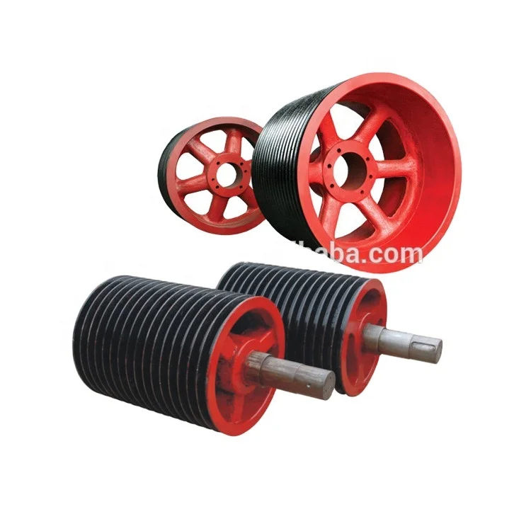
Mud Pumps are available for the different purposes of drilling and extracting of oil. In fact, the Unitized Pumps are a work of the hydraulic mechanical transmission. Unitized pump parts include 4 types of packages such as the air clutch transmission takes in the diesel engine, transmission (including card and shaft, decelerator, clutch, belt and pulley) and the Mud pump. The Mud Pumps are also inclusive of the hydraulic coupling transmission that consists of the diesel engine, hydraulic coupling and the Mud pump. It also includes the electric drive Mud pump and the chain transmission for apt design and assembling.
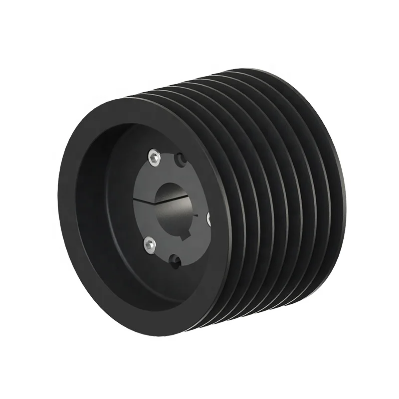
The Unitized design Pumps are built as well as licensed according to the specifications of the American Petroleum Institute where the master skid is the standard oilfield 3 runner skid. Mud Pumps like the F 1000 are driven by the diesel engine with the help of the narrow V belts. Pumps are complete with a bulk wheel, a set of V belts, a screw assembly, a belt guard and the screw devices for tightening the belts. Mud pump like the triplex liner single action pumps has an input power of 1000 horse power. The maximum stroke is all of 10 inches or 254 mm.
Mud parts also contain a maximum working pressure of 5000 PSI or 35 MPA. The Mud Pumps have a gear type made of integral herring bone with API 6 valve pots. The intake of the F 1000 Pumps is 12 inches or 305 mm and they have a discharge space of 4 inches or 102 mm. Mud pump also contain a pulsation dampener model that has a capacity of 75.7 liters or 20 gallons. The relief valve and pressure gauge are also an important part of the Mud pump as they help in various ways.
Mud pump like the diesel engine has a rated speed of about 1200 revolutions per minute and the movement takes place in an anticlockwise direction with the face output shaft end. For the purpose of testing and commissioning, the Mud pump needs to be installed and secured with machinery and different kinds of equipment. Furnish the lube products for testing and the diesel is required to be run for testing the transmission devices. To give you an idea, the Mud pump that is being discussed in this category is available at competitive prices and can be obtained for pneumatic clutch transmission that can be adjusted according to customer’s requirements.

If your conveyor belt isn’t working properly, it will have untold ramifications throughout your entire system. Entire operations can be thrown off schedule, resulting in loss of both money and productivity.
To prevent this from happening, you need to keep a close eye on the precise workings of your conveyor belts. By carefully watching and checking up on your belts, you can catch many problems before they develop into larger issues that take time and money to fix.
It’s crucial for you to understand how to complete conveyor belt maintenance as well as what some of the more common conveyor belt problems are and how to fix them. This information will help you keep your conveyor belts running smoothly and stop them from breaking down due to preventable issues.
While it is impossible to compile a list of every bad situation you will ever encounter with your conveyor belt, this is a list of some of the concerns you are most likely to face, as well as their probable consequences.
This issue occurs when there is a conveyor belt tracking problem. Tracking is the process of managing and aligning the belt onto the correct path, and it’s critical to ensuring the smooth functioning and output of your system. Mistracking, then, is when something goes wrong along this track. In most cases, it means that the belt has slipped to one side or another, and the entire system has shifted out of alignment.
Mistracking leads to numerous negative consequences. It has the potential to throw the entire system off its specified course. But the consequences can also be less extreme than this. Mistracking might simply lead to uneven belt wear, which is the cause of a whole host of other problems in its own right.
If the belt slips entirely off the track, the whole system could begin malfunctioning and shut down. It’s best to keep an eye out for small signs of mistracking, even if they don’t seem to be causing much damage. By catching this problem early on, you can prevent it from worsening and creating a larger issue.
When your belt starts tracking from side to side and experiencing frayed edges, you need to do a little conveyor belt alignment troubleshooting. Conveyor tracking problems can originate from various parts of your system. As soon as your belt starts mistracking, take a look at these potential problems:
Conveyor frame: If your conveyor frame is crooked or slanted, it could be misguiding your belt. Check your framework from all angles to ensure the frame is level and square.
Snub rollers: These rollers create more tension in your belt and make contact with every pulley in the system. Tenison is crucial to tracking, so your snub rollers should align with your frame and apply enough tension to the belt.
Belt cutting:Conveyor belts can be cut incorrectly during manufacturing, making them crooked. No matter how well the rest of your system runs, a crooked belt will cause tracking errors.
Cleanliness: Buildup on the belt and pulleys can cause the belt to sway one way or another. Make sure all parts of your conveyor are clean to ensure a smooth run and prevent failure.
False crowns: Conveyor belts move a variety of items, and sometimes the material can snag or get stuck on a pulley. You can find crowns on the center of your end pulleys that distribute force to each side of the belt and help it stay on track. If a piece of debris gets lodged in another pulley, it can create a fake crown and redistribute weight where you don’t need it. Check to see if your pulleys are clear of debris to avoid this.
Conveyor belts rely on a precise balance of tension to work correctly. If there is too much tension or too little, things begin to go awry, and the belt can slip. Specifically, if the head pulley breaks down or even becomes overly worn, there will no longer be enough tension to keep the belt from slipping around.
This loss of tension can result in unnecessary stretching and strain on the belt, as well as loud, grating and squealing noises and the aforementioned slipping. It will require time-consuming maintenance to fix such a problem as this. To avoid this situation, check all parts and pieces of the conveyor belt regularly to ensure that they aren’t experiencing any undue wear and tear.
Since tension and balance play massive roles in belt operation and traction, there are a few common causes of belt slippage. Once you’re aware of the potential causes, you can keep an eye on problem areas to prevent slippage in the future. Common causes include:
Overweight load.Your conveyor belt can only handle so much weight based on its pulleys and overall size. If you’ve tried to carry something that’s exceedingly heavy, your belt will typically slip off the pulleys instead of operating normally. Make sure the objects you’re using on your belt fit the belt’s weight range.
Low temperatures.If you’re working in colder conditions than usual, it could affect the traction of your conveyor belt. Colder temperatures can reduce the grip between the belt and pulley, causing the belt to slip. If you regularly work in cold environments, choose a belt designed to withstand low temperatures.
Poorly installed lagging.While incorrect belt tension results from a variety of problems, lagging typically fixes those issues. Lagging is applied to the pulleys to improve grip with the belt, but if this lagging is improperly installed, you may still experience slippage. If you’re not sure how to install pulley lagging yourself, consult a professional.
Pulley problems.Pulleys are a common source of tension issues. Worn heads or pulleys with buildup can reduce the belt’s grip, as can a pulley that’s too smooth. The best way to prevent pulley problems is to actively check them for signs of wear.
When your conveyor belt constantly slips, it disrupts your daily operation and productivity. If you stay aware of the potential causes, you can prevent them before they happen. It’s helpful to regularly inspect your machine, especially the pulleys as they often contribute to belt slippage.
In most cases, conveyor belts are constructed from metallic materials such as steel. This construction is good because it means the parts are usually highly durable and long-lasting. However, it also means that when the rollers on the conveyor belt seize up, they have an unfortunate tendency to develop sharp edges.
These sharp edges, in turn, can have major repercussions throughout the conveyor system. They can cause the belt to mistrack unequally down the center line of the conveyor belt. This circumstance is an issue for several reasons. Firstly, it can pose a significant safety hazard to any workers in proximity to the conveyor belt. Secondly, it has the potential to damage goods and materials being transported along the conveyor belt, sometimes beyond repair.
The primary purpose of any conveyor belt system is to transport items efficiently from one location to another, often through a complex conveyor system. It only makes sense, then, that when this efficient travel is disrupted, the entire system stops working.
It’s all too easy for a package to get caught. When this happens, the next item behind the first one gets caught, and the pileup simply builds from there. It can lead to the entire system becoming clogged and jammed.
While random occurrences are hard to predict and often impossible to prevent, you can do a great deal to stop preventable blockages. Check your conveyor belts carefully for any sharp edges, surfaces, corners or other spaces that might snag items as they go past. Remember that even if something looks like it’s not a big deal now, it’s always better to deal with it while it’s still small. Otherwise, it might soon become a much larger complication.
While blockages are a result of packages getting caught on sharp edges and blocking the other products, material carryback involves a buildup of material on the belt itself. If you’re working with materials such as clays or mineral ores, they can leave small amounts of residue behind. While it may not seem like much, this material will increase and lead to accumulation underneath your belt, causing problems with your rollers and pulleys.
This carryback can also cause safety issues down the road because excessive material buildup can be a fire hazard, and certain materials can be dangerous if frequently inhaled. There’s also a profit loss associated with carryback. If you’re working with high-profile materials and losing a little bit of them every time they’re on the belt, you could lose a significant profit.
It’s fairly common for there to be some issues with material spillage at some point along a conveyor system. This term refers to any material that accidentally slides or spills off the belt, and it’s most common along transfer and load points. This occurrence isn’t necessarily due to any mechanical failures or problems with the belt, but it can still be an issue, as this spilled material can lead to blockages or buildups that will have a domino effect and cause other problems later on.
If you find that material spillage is a common factor on your conveyor belt, try installing impact beds, skirt clamps or a belt plough. These solutions will help reduce wasted material as well as time spent cleaning up, and they’ll decrease the possibility of breakdowns caused by blockages on the belt.
Depending on the product you’re moving, you might experience perforations or tears in your belt. Moving products such as sharp rocks or coal increases the chances of this occurrence. Even excessive friction from moving heavy packages can result in thin spots that eventually lead to tears. Seam rips also happen over time with stress and tension on the belt. Tears and rips can be hard to prevent with the nature of your operation, so this problem requires a good repair process.
A torn belt or ripped seam can cause problems with the function of your belt and hurt productivity. It’s important to either contact a professional or have a trained member of your team perform these repairs to reduce downtime.
There is a broad range of solutions for conveyor belt problems that you can consider to make repairs. These repairs depend on the belt’s material, your industry and how much space your operation has.
Vulcanization:This process uses pressure and heat to fix tears in your belt. It’s the most reliable repair method, and it applies to both thermoset rubber and thermoplastic belts.
Metal fasteners:This repair method is the most common do-it-yourself option because it’s quick and easy. By using metal fasteners, you can essentially stitch your belt together. While this is a quick fix, it’s not as reliable and will not last as long as vulcanization. Fasteners also pose a risk of falling off and joining your product line, so it’s particularly unsafe for the food industry. Use this method as a backup option or a temporary fix before vulcanization.
Cold curing:This method is also known as cold vulcanization, and it’s often used for gouges or scoring on your belt. It involves a cement made with a base compound and curing agent, and it’s applied like a paste. This repair type is typically used when an operation has space constraints and can’t accommodate regular vulcanization equipment.
As part of the regular checkups you perform on your conveyor belt, you should complete a routine cleanliness check. Carefully look over your entire system from top to bottom, side to side and every way you can think of. Look for buildups of dirt, debris or residue of any kind. Wherever you find these types of buildup, remove them as thoroughly as possible.
Debris is a common cause of mistracking. It can cause the belt to become aligned incorrectly, and it can also be responsible for blockages in your system.
Pulleys are easy to check at the same time that you’re already investigating whether the frame is square. Verify that each pulley in the system is evenly lined up with the conveyor frame. If these pulleys are off, this could lead to bigger problems with the belt slipping and parts wearing down more quickly.
This feature isn’t necessarily something you need to check every time you perform maintenance since looking at it once will get the job done. However, it’s still crucial to perform this analysis. While ideally, every belt is cut and formed perfectly, it’s not impossible that you may have gotten a defective belt that simply isn’t cut straight. If you didn’t know about this defect, it could be wreaking all kinds of havoc in your conveyor system through mistracking.
To check whether or not your belt is straight, try this. Remove the belt from the conveyor frame and lay it out flat on the floor. If the belt arcs or curves in any way, it isn’t straight, and it will need to be replaced.
The conveyor belt’s return idlers can become dirty, frozen or incorrectly aligned over time due to improper installation or natural wear, tear and motion. These parts should be cleaned regularly, and their alignment should be checked.
If your idlers freeze or stop working in any way, it could have various ramifications for your system. It could lead to your belt wearing out faster than usual and needing to be replaced, among other possibilities. To avoid this situation, simply check the idlers regularly for any problems, cleaning them as they become dirty and replacing them as they begin to wear out.
Belt maintenance is crucial for an efficient product line. If you actively check your conveyor belt’s activity and prepare to handle problems, your operation will run smoothly. Keep these maintenance tips in mind when caring for your conveyor belt:
This is valuable for belts that you actively use throughout the day. Have a plan for emergency repairs by stocking equipment such as cold-curing supplies or metal fasteners so you can repair rips quickly. It’s also wise to have a plan of action for production. Will you stop that line completely, or can you move it elsewhere while you make repairs?
You should also keep a stock of spare parts. Things such as sprockets, motors and belts will need to be replaced over time. Keep them available if any part failure should arise.
How long do your conveyor belts typically last with your type of production? If you have a belt that doesn’t meet that standard lifespan, it could indicate a manufacturing error or even poor maintenance and care. If you know how long a belt lasts, you can make sure you’re actively caring for it to support that lifespan.
The best way to avoid a severe malfunctioning error is to follow the steps listed above. Following these tips can improve your conveyor belt’s lifespan and help you avoid bigger problems, ultimately making your line more productive.
Make a note of any repairs you perform, and write down the state of your parts regularly in a conveyor belt plan. If a more significant problem comes up, you could access these notes to see repairs you’ve made in the past, and if the state of your belt showed failure over time.
As much as preventive maintenance is a good practice, working with a professional technician for belt maintenance services guarantees that the bigger repairs will be done correctly. Set up regular maintenance with a professional so they can fill in the gaps of your actions.
This point cannot be stressed enough. Do not perform maintenance on the conveyor system while it is in use. Doing so would be a good way to get a finger crushed or broken if your fingers happen to get caught in the machinery. Even more dangerous is the electrical current powering the conveyor belt. To avoid problems with dangers such as these, take extra precautions. Be safe and make sure everything is shut off before you begin maintenance.
The amount of electricity needed to power a conveyor system is nothing to take lightly. That kind of power can cause serious damage, especially if you’re inexperienced and aren’t especially sure what you’re doing. If you begin to suspect that the problem with your conveyor belt is much more involved than anything we’ve covered here, take a step back. It may be time to call in a professional maintenance team. While this may seem like an extra hassle, it’s always better to be safe than to end up seriously damaging your system or endangering yourself or an employee.
If you find yourself in over your head with repairing or maintaining your conveyor belt, sometimes the best thing you can do is to call a professional who is equipped with the correct conveyor belt maintenance tools.
While we are located in St. Louis, Missouri, we also serve Illinois, Indiana, Kentucky, Iowa and Kansas. We value operations having access to conveyor belt products and services, so we serve as many areas as possible. We’re ready to provide you with our top-of-the-line products and services anytime you need. Contact us online today to request a quote, or call us at 314-371-4777.


 8613371530291