
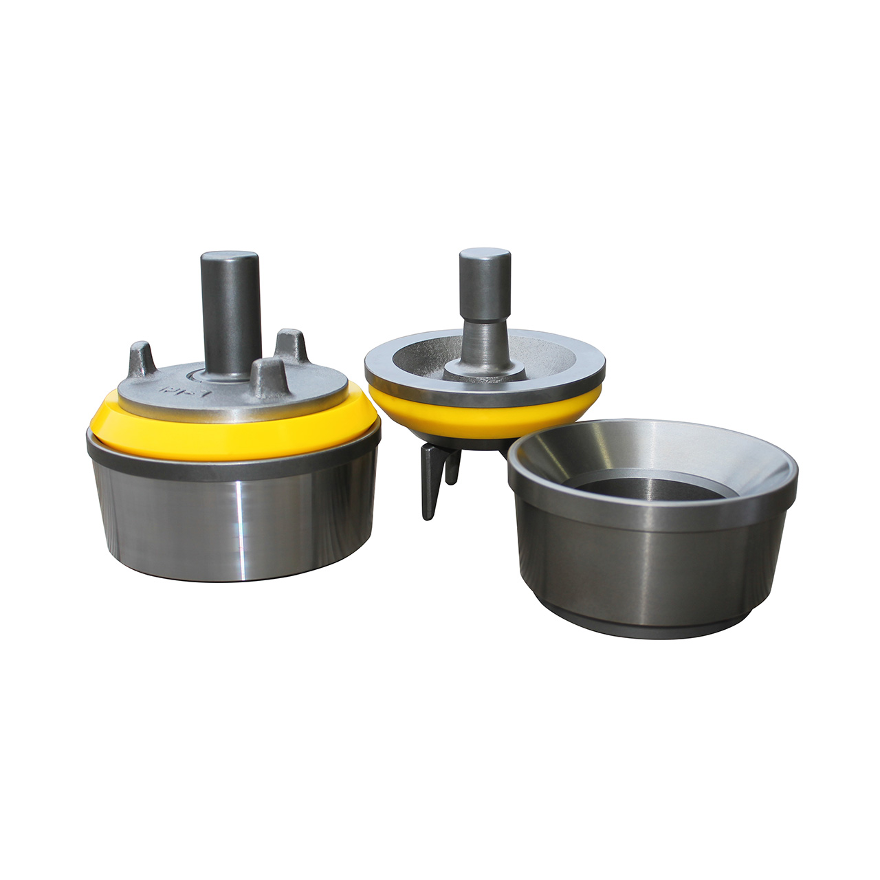
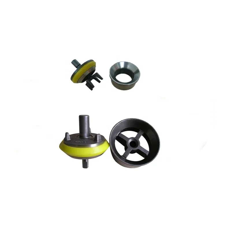
mud pump valves and seats free sample

My invention relates to valves of the character employed in mud pumps or other pumps adapted to pump fluid mixtures containing abrasive materials, and relates particularly to an improved form of such valve capable of longer periods of uninterrupted use than valves which are at present employed in pumps of this character.
Mud pump valves of the character to which my invention relates are subject to very rapid wear owing to the presence of abrasive materials, such -as fine particles of rocks, quartz, or sand contained in the drilling fluid or mud, and therefore must be replaced after comparatively short periods of use. Such valves ordinarily include a seat member consisting of an annular ring with a sealing seat near the upper end thereof and a spider structure across the lower portion thereof, and a valve element including a body of metal adapted to strike against the spider when the valve element is in lowered or relatively closed position and a sealing member on the metal body adapted to engage the sealing face of the seat member and prevent leakage of fluid through the valve when the valve is in its closed position. It is an object of my invention to provide a valve of the above character of simple construction yet being capable of giving a greater period of service than valves of complex structure.
It is an object of the invention to provide a valve having a seat member including an annular sealing face or seat and a valve closure member having a circular or annular sealing member of rubber material adapted to enter the space enclosed by the annular sealing seat or face of the seat member and to be deformed by fluid pressure so as to expand against the sealing face of the seat member.
It is a further object of the invention to provide a valve of the above character in which the cooperative parts are so formed that the sealing member preferably wipes the sealing face clean as it moves into closed position, thereby reducing to a minimum the particles of abrasive material which may rest between the sealing member and the sealing face, the result thereof being that the wear between these parts is minimized and the useful life of the valve materially extended.
It is a further object of the invention to provide a valve which may be used for abrasive subo5 stances and which may be also employed in pumps for circulating other fluids, such as crude oils.
It is a still further object of the invention to seal the valve by a sealing member on the valve body having a peripheral annular engagement surface adapted to be received within an annular inwardly faced sealing wall surface of the valve seat, whereby the engagement surface is adapted to be deformed radially outwardly for sealing engagement with the sealing wall surface, the seating movement of the valve body being limited by its engagement with a supporting surface of the seat member, and said supporting surface being at an angle to the direction of opening and closing movement of the valve appreciably greater than the angle of the sealing surface with relation to the direction of opening and closing movement of the valve. The supporting surface thus takes the blow and relieves the sealing member of excessive wear as the valve closes, and by its appreciable angle to the axis of the valve prevents radial distortion of the seat member or *swedging action such as might deform the seat or the valve body, while the smaller angle of the sealing surface with relation to the axis of the valve, insures a tight sealing engagement by radially deforming and confining the sealing member within the inwardly faced annular sealing wall surfade, rather than by merely pressing the sealing member against a cooperating surface lying at an appreciable angle to the axis of the valve.
Further objects and advantages of the invention will be made evident throughout the following part of the specification. Referring to the drawings, which are for illustrative purposes only, Fig. 1 is a partly sectioned elevational view showing a mud pump equipped with valves embodying my invention. Fig. 2 is an enlarged fragmentary cross section showing one of the valves in closed position.
Fig. 6 is a fragmentary sectional view showing a form of my invention adapted for use in other types of pumps, such as oil pumps. Fig. 7 is a section on a plane represented by the line 7-7 of Fg. 2.
In Fig. 1 I show a reciprocating pump 10 having a pumping cylinder I in which a piston 12 is reciprocated by a steam powered engine 13. The rightward portion of the pump 10 is sectioned so as to show discharge valves 14 which are connected with the opposite ends of the cylinder II so that as the piston 12 is reciprocated, fluid will be forced upwardly from the respective ends of the cylinder into an outlet chamber 15 which in mud pumps is connected through a rotary hose to the rotary drilling string.
As shown in Fig. 2, the preferred embodiment of my improved valve 14 includes a seat member 16 and a valve body or closure member IT which moves relative to the seat member 16. The seat member 16 includes an annular wall 18 and a support or spider 20 which extends across the lower portion of the annular wall 18, this spider 20 comprising a number of radial arms 21 extending inwardly from the annular wall 18 and a central hub 22 having an axial opening 23 therein.
Above the spider 20 the annular wall 18 is formed with an annular sealing surface 24. This sealing surface is shown as preferably flaring outwardly and upwardly at a comparatively steep angle; or the sealing surface may have no taper but be cylindrical as will be later described with reference to Fig. 5, it being the steep angle of the sealing surface that greatly contributes to the improved operation and wear resisting qualities of my new valve. The valve body I1 is in the form of a metal enlargement 25 having a lower abutment area which includes abutment surfaces adjacent both"the axis and the periphery of said enlargement and adapted, when the valve is closed, to engage the upper face of the hub 22 and the radial arms 21 which constitute the spider. The abutment surface of the enlargement 25 which is adjacent the periphery thereof engages the abutment formed by the arms 21 adjacent and extending inwardly from the annular wall 18, and the abutment surface of the enlargement 25 which is adjacent the axis thereof engages the abutment formed by the hub 22 adjacent the axis of the valve. The enlargement is equipped with guide means in the form of upwardly and downwardly projecting axial stems 26 and 27 of Sthe character commonly employed in mud pump valves. On the upper face of the body IT is a sealing member 30 consisting essentially of a flat disc of yieldable material, such as rubber or rubber compound, having an opening 31 therein through which the stem 26 projects, the sealing member 30 being held in place on the body 1I by a flange member 32 which is held down against the upper face of the sealing member 30 by means of a pin 33 extended through the stem 26. The sealing member 30 is of such external diameter that it will enter the space enclosed by the surface 24 as the closure member T1 moves from the open position in which it is shown in Fig. 3 to the closed position in which it is shown in Fig. 2. As the member I7 moves to closed position fluid pressure within the chamber 15 is exerted downwardly against the annular upwardly directed surface 34 of the sealing member 30 exposed around the flange 32, such pressure compressing the rubber or yieldable material of the peripheralportion of the sealing member 30 against the upper face of the body 17 and causing the periphery of the sealing member 30 to be expanded or deformed radially outwardly so as to be confined within and radially contact the surrounding annular wall surface 24. The sealing member 30 is shown with a shallow peripheral groove 35 so as to form the semblance 7 of a lip 36, but for some uses satisfactory results may be obtained where the upper face of the sealing member 30 is left flat.
Another feature of the invention which may be employed, is to make the diameter of the sealing member 30 of such measure relative to the diameter of the sealing surface 24 that the fluid pressure in the chamber 15 will cause the peripheral face 37 of the sealing member to make wiping contact with the -surface 24 as the closure member 17 moves toward closed position. The sealing member 30 may be of such size that when the body IT, during its downward movement, reaches the position indicated by the dotted lines in Fig. 3, the fluid pressure in the chamber 15 will cause the lower edge of the peripheral face 37 of the sealing member 30 to engage the upper edge of the wall surface 24. As the closure member 14 then continues downwardly toward fully closed position, such as shown in Fig. 2, the surfaces 24 and 37 wipe across one another and remove from each other much of the collected material. It may be that fine abrasive materials will remain on the surfaces 24 and 37, but the condition of the valve after it has been in use for a considerable period of time indicates that this wiping action at least removes the larger partides of material which would prevent a sealing action between the periphery of the sealing member 30 and the wall surface 24. For illustration, as the closure member 17 moves to closed position, the lower peripheral corner 37" of the sealing member may wipe materials from the wall surface 24, and the upper annular corer 38 of the wall surface 24 may wipe materials from the face 37 of the sealing member 30, leaving these surfaces in such condition that a practical seal will, result. .For example, the seal formed is of such practical efficiency that I have been able to employ a single valve structure continuously for a period of over ninety days, replacing the sealing member but once during this period. At the time of signing this application this valve is still in use with the second rubber or sealing member 30.
For this purpose the flange member 32 is of such restricted diameter that the enlargement 25 as well as the sealing member 30 project appreciably radially beyond the flange member. An appreciable area of the upper surface of the sealing member is thus exposed to the fluid pressure in chamber 15 for tightly seating the sealing member against wall surface 24, and in the event of the metal parts of the assembly being excessively worn so that the sealing member 30 is forced further down into the annular seat 24 before tightly closing the valve, the restricted diameter of the flange member 32 permits such flexing of the outer peripheral portion of the sealing member 30 as will readily adapt it to its new seating position, with said flexing of the outer peripheral portion of the sealing member avoiding cutting through and destruction of the sealing member.
In Fig. 5 I show a form of my invention which is exactly the same as the valve shown in Figs. 2 and 3 with the exception that the sealing face or inwardly directed wall surface 24a is cylindrical for a greater part of its length and is slightly chamfered at the corner 38a. Corresponding to the surface 24a, the peripheral surface 37a of the sealing member 30a is cylindrical and may be of such diameter that responsive to fluid pressure, wiping engagement between the surfaces 24a and 37a will be accomplished as the closure member 17a moves into the closed position shown in Fig. 5, it being understood that upon reaching such closed position, fluid pressure against the sealing member causes radial expansion of its annular face 34a into tight sealing engagement with the surface 24a.
In Fig. 5 the wall surface 24a is shown cylindrical for a portion of its length and slightly flared at its upper end. In Figs. 2, 3, and 4, the wall surface 24 is shown comparatively steeply upwardly flared for the purpose of self-adjustment of the parts as the upper face of the support or spider wears down due to the repeated hammering of the body 17 thereagainst during the operation of the pump. Accordingly, in the preferred practice of my invention the wall surface 24 may have such a comparatively steep angle that the annular peripheral engagement surface of the sealing member is adapted to be radially expanded and confined within the annular wall surface 24, and moves relative to surface 24 in the direction of closing movement of the valve so as to permit ready dislodgement of abrasives rather than trapping the same between the surfaces 24-37; and the wall 24 may be flared at such a steep angle as to compensate for the wear between the surfaces 24 and 37 and between the bottom of the body 17 and the upper face of the support 20. As the stopping position of the body 17 moves downwardly as the result of the last named wear, the sealing member, which has worn slightly, assumes a stopping position relative to a lower portion of the wall surface 24 of slightly reduced diameter.
In Fig. 6 I show an alternative form of my valve having a seat member 16 of a form identical with the illustration thereof in Figs. 2, 3, and 4. In this form of the invention, however, the sealing member 30 is replaced by a dished or cupshaped sealing member 50 having a circular wall 51 and an upturned, slightly upwardly flared lip or wall 52 which provides an outer surface 53 adapted to enter the annular wall surface 24 and to be forced outwardly by fluid pressure against the upper and inner faces of the lip 52. The sealing member 50 may be made of leather and may be held in place on the body 17 by use of a flat metal disc 54 of a size to fit under the holddown flange 32. This alternative form of my invention isespecially designed for use in high pressure oil pumps or high pressure pumps for transferring other liquids. The same wiping action between the surfaces 24 and 53 of the members 16 and 50 may be accomplished, and the pounding effect due to the high pressure on the upper face of the movable valve part is received by the spider or support 20.
Another feature of the invention is that the supporting of the seat member which takes the blow when the valve closes, is at an appreciable angle to the direction of opening and closing movement of the valve, while the sealing engagement between surfaces 24-37 is at a slight angle to the direction of opening and closing movement. For example, as shown at Fig. 2, the surface 24 flares upwardly and radially outwardly at a steep angle, and the engagement surface 37 of the sealing member flares upwardly and radially outwardly at substantially the same steep angle; while the upper surface of- pider 20 which provides the abutment surface which takes the blow when the valve closes, is at an angle which is not nearly as steep.
Consequently the hammering blow of the closing valve is directed against the cooperating support of the seat member, at an angle which is at least a near approach to a right angle, so as to avoid swedging action or radial distortion of the seat member; and the sealing engagement at surfaces 24-37 is in a plane which is either parallel or close to parallel to the direction of movement of the valve, whereby material will readily dislodge from between the surfaces 24-37, and the sealing engagement is made by radially outwardly deforming and confirming the sealing member within the annular wall 24. The arresting abutment and the sealing engagement at different angles to the axis of the valve, with the arresting abutment at the greater angle, thus cooperate to define a construction wherein the valve is seated without undue wear of the sealing member and without distortion of either the valve seat or the valve body, and with foreign material dislodged from between the body and seat, and the sealing engagement resulting from radial expansion and confinement of the sealing member within an annular sealing wall of the valve seat.
Although I have herein shown and described my invention in simple and practical form, it is recognized that certain parts or elements thereof are representative of other parts, elements, or mechanisms which may be used in substantially the same manner to accomplish substantially the same results; therefore, it is to be understood that the invention is not to be limited to the details disclosed herein but is to be accorded the full scope of the following claims.
I claim as my invention: 1. A valve of the character described, including: a seat member comprising an annular wall of short tubular form and a support consisting of an open-work structure extending across one end of said annular wall, the other end of said annular wall providing an outwardly flared, inwardly faced sealing wall surface; a valve body adapted to move to and from said support, said valve body comprising a guide means and an enlargement adapted to engage said support; and an annular sealing member on the upper face of said enlargement having an outwardly flared resilient peripheral portion providing an annular engagement surface adapted to engage said wall surface as said valve body moves into engagement with said support and being of such diameter relative to said wall surface as to engage said wall surface at a point b3fore said enlargement engages said support and to have a wiping movement relative to said wall surface as said enlargement moves from said point into engagement with said support, there being a space below said annular engagement surface to receive the wipings removed from said wall surface by said annular engagement surface, and the peripheral portion of the upper face of said sealing member being exposed to fluid pressure whereby such fluid pressure may deform the periphery of said sealing member outwardly to increase the pressure of the sealing engagement of said sealing member with said wall surface.
2. A valve of the character described, including: a seat member comprising an annular wall of short tubular form and a support consisting of an open-work structure extending across one end of said annular wall, the other end of said annular wall providing an outwardly flared, inwardly faced sealing wall surface; a valve body adapted to move to and from said support, said valve body comprising a guide means and an enlargement adapted to engage said support; and an annular sealing member on the upper face of said enlargement having an outwardly flared resilient peripheral portion providing an annular engagement surface adapted to engage said wall surface as said valve body moves into engagement with said support and being of such diameter relative to said wall surface as to engage said wall surface at a point before said enlargement engages said support and to have a wiping movement relative to said wall surface as said enlargement moves from said point into engagement with said support.
3. A valve of the character described including: a seat member comprising an annular wall and a support below the upper end of the annular wall, the upper end of the annular wall providing an outwardly flaring annular sealing surface; a valve body adapted to move to and from the support, said valve body comprising a guide means and an enlargement adapted to engage the support; and an annular sealing member on the upper face of said enlargement having a resilient peripheral portion providing an annular engagement surface adapted to engage 5o said annular sealing surface as the valve body moves into engagement with the support and being of such diameter relative to the annular sealing surface as to engage said annular sealing surface at a point before said enlargement en5. gages the support and to have wiping movement relative to the annular sealing surface as said enlargement"moves from said point into engagement with the support, there being a space below the annular engagement surface of suffi(; cient size to receive materials wiped from the annular sealing surface by the sealing member as said sealing member moves into closed position relative to the seat member.
4. A valve of the character described includ5, ing: a seat member comprising an annular wall and a support below the upper end of the annular wall, the upper end of the annular wall providing an outwardly flaring annular sealing surface; a valve body adapted to move to and fronh 7o the support; and an annular sealing member on the upper face of the body having an outwardly flared resilient peripheral portion providing an annular engagement surface adapted to engage said annular sealing surface as the valve body moves into engagement with the support and being of such diameter relative to the annular sealing surface as to engage said annular sealing surface at a point before the body engages the support and to have wiping movement relative to the annular sealing surface as the body moves from said point into" engagement with the support, the peripheral portion of the upper face of the sealing member being exposed to fluid pressure whereby such fluid pressure may deform the periphery of the sealing member to increase the pressure of the sealing engagement of the sealing member with the annular sealing surface.
5. A valve of the character described, including: a seat member comprising an annular wall and a support below the upper end of the annular wall, the upper end of the annular wall providing an outwardly flaring annular sealing surface; a valve body adapted to move to and from the support; an annular sealing member on the upper face of the body having a resilient peripheral portion providing an annular engagement surface adapted to engage said annular sealing surface as the valve body moves into engagement with the support and being of such diameter relative to the annular sealing surface as to engage said annular sealing surface at a point before the body engages the support and to have wiping movement relative to the annular sealing surface as the body moves from said point into engagement with the support; and a retaining member overlying the sealing member and of a diameter whereby the sealing member and the valve body project radially beyond the retaining member, so that the peripheral" portion of the sealing member may be flexed to accommodate it to the annular sealing surface and the upper face of said peripheral portion of the sealing member is exposed to fluid pressure whereby such fluid pressure may deform the periphery of the sealing member to increase the pressure of the sealing engagement of the sealing member with the annular sealing surface.
6. In a valve; a seat member comprising an annular wall and an abutment surface below the upper end of and in the bore defined by the annular wall, the abutment surface being adjacent the axis of the annular wall, the upper end of the annular wall providing an outwardly flaring annular sealing surface; a valve body adapted to move to and from the abutment surface parallel to the axis of the annular wall, the abutment surface being adapted for engagement by the valve body at an angle to the axis of the annular wall appreciably greater than the angle of the annular sealing surface to said axis; and an annular sealing member on the valve body having a resilient peripheral portion providing a peripheral engagement surface normally, flaring at substantially the same angle as that of the an- go nular sealing surface and of such diameter as to engage said annular sealing surface before the valve body engages the abutment surface, the peripheral portion of the sealing"member being exposed to fluid pressure for deforming its flar- g6 ing peripheral engagement surface for sealing contact with the annular sealing surface.
7. In a valve; a seat member comprising an annular wall and an abutment surface below the upper end of and in the bore defined by the annular wall, the upper end of the annular wall providing an outwardly flaring annular sealing surface; a valve body adapted to move to and from the abutment surface parallel to the axis of the annular wall, the abutment surface being adapted for engagement by the valve body at an angle to the axis of the annular wall appreciably greater than the angle of the annular sealing surface to said axis; and an annular sealing member on the valve body having a resilient peripheral portion providing a peripheral engagement surface normally flaring at substantially the same angle as that of the annular sealing surface, said peripheral portion of.the sealing member being of such diameter and exposed to fluid pressure so that its flaring peripheral engagement surface engages the annular sealing surface before the valve body engages the abutment surface, and seals against the annular sealing surface when the valve is closed.
8. In a valve; a seat member comprising an annular wall and an abutment surface below the upper end of and in the bore defined by the annular wall, the upper end of the annular wall providing an outwardly flaring annular sealing surface; a valve body adapted to move to and from the abutment surface parallel to the axis of the annular wall, the abutment surface being adapted for engagement by the valve body at an angle to the axis of the annular wall appreciably greater than the angle of the annular sealing surface to said axis; and an annular sealing member on the valve body having a resilient peripheral portion providing a peripheral engagement surface normally flaring at substantially the same angle as that of the annular sealing surface, said peripheral portion of the sealing member being of such diameter and exposed to fluid pressure so that its flaring peripheral engagement surface engages the annular sealing surface before the valve body engages the abutment surface, and seals against the annular sealing surface when the valve is closed; and there being space below said flaring peripheral engagement surface when the valve is closed, adapted to receive material dislodged from the annular sealing surface.
9. In combination; a valve body adapted to move to and from a cooperating annular valve seat parallel to the axis of the valve body; and an annular sealing member on the valve body having, a resilient peripheral portion providing a peripheral engagement surface normally flaring upwardly and outwardly, the valve body having an abutment surface adapted to engage the valve seat, said abutment surface being at an angle to the axis of the valve body appreciably greater than the angle of said flaring peripheral engagement surface to said axis, the flaring peripheral engagement, surface being of such diameter as to engage the valve seat before the abutment surface of the valve body engages the valve seat, and the peripheral portion of the sealing member being exposed to fluid pressure for deforming its flaring peripheral engagement surface for sealing contact with the valve seat.
10. In combination; a valve body adapted to move to and from a cooperating annular valve seat parallel to the axis of the valve body; and an annular sealing member on the upper face of the valve body having a resilient peripheral portion including an upstanding lip providing a peripheral engagement surface normally flaring upwardly and outwardly, the valve body having abutment surfaces adjacent both the periphery and the axis thereof adapted to engage the valve seat, said abutment surface being at angles to the axis of the valve body appreciably greater than the angle of said flaring peripheral engagement surface to said axis, the flaring peripheral engagement surface being of such diameter as to engage the valve seat by the time the abutment surfaces of the valve body engage the valve seat, and the lip of the sealing member being exposed to fluid pressure for deforming the flaring peripheral engagement surface of the sealing member for sealing contact with the Valve seat.
11. In combination; a valve body adapted to move to and from a cooperating annular valve seat parallel to the axis of the valve body; and an annular sealing member on the valve body having a resilient peripheral portion providing a peripheral engagement surface normally flaring upwardly and outwardly, the valve body having an abutment surface adjacent the periphery thereof adapted to engage the valve seat,"said abutment surface being at an angle to the axis of the valve body appreciably greater than the angle of said flaring peripheral engagement surface to said axis, the flaring peripheral engagement surface being of such diameter as to engage the valve seat by the time the abutment surface of the valve body engages the valve seat, and the peripheral portion of the sealing member being exposed to fluid pressure for deforming its flaring peripheral engagement surface for sealing contact with the valve seat.
12. In combination; a valve body adapted to move to and from a cooperating annular valve seat parallel to the axis of the valve body; and an annular sealing member on the valve body having a resilient peripheral portion providing a peripheral engagement surface normally flaring upwardly and outwardly, the valve body having an abutment surface adjacent the axis thereof adapted to engage the valve seat, said abutment surface being at an angle to the axis of the valve body appreciably greater than the angle of said flaring peripheral engagement surface to said axis, the abutment surface being rigid throughout its area, the flaring peripheral engagement surface being of such diameter as to engage the valve seat by the time the abutment surface of the valve body engages the valve seat, and the peripheral portion of the sealing member being exposed to fluid pressure for deforming its flaring peripheral engagement surface for sealing contact with the valve seat.
13. In combination; a valve body adapted to move to and from a cooperating annular valve seat parallel to the axis of the valve body; and an annular sealing member on the valve body having a resilient peripheral portion providing a peripheral engagement surface normally flaring upwardly and outwardly, the valve body having an abutment surface adapted to engage the valve seat, said abutment surface being at an angle to the axis of the valve body appreciably greater than the angle of said flaring peripheral engagement surface to said axis, the abutment surface being rigid throughout its area, the flaring peripheral engagement surface being of such diameter as to engage the valve seat by the time the abutment surface of the valve body engages the valve seat, and the peripheral portion of the sealing member being exposed to fluid pressure for deforming its flaring peripheral engagement surface for sealing contact with the valve seat.
14. In a valve; a seat member comprising an annular wall and an abutment surface below the upper end of and in the bore defined by the annular wall, the abutment surface being adjacent the axis of the annular wall, the upper end of the annular wall providing an outwardly flaring annular sealing surface; a valve body adapted to move to and from the abutment surface parallel to the axis of the annular wall, the abutment surface being" adapted for engagement by the valve body at an angle to the axis of the annular wall appreciably greater than the angle of the annular sealing surface to said axis; an annular sealing member on the upper face of the valve body having a resilient peripheral portion including an upstanding lip providing a peripheral engagement surface normally flaring at substantially the same angle as that of the annular sealing surface and of such diameter as to engage the annular sealing surface by the time the valve body engages the abutment surface; and a retaining member overlying the sealing member and of a diameter less than that of the upstanding lip whereby said lip is exposed to fluid pressure for deforming its flaring peripheral engagement surface for sealing contact with the annular sealing surface; there being space below said flaring peripheral engagement surface when the valve is closed, for reception of material dislodged from the annular sealing surface. 15. In a valve; a seat member comprising an annular wall and an abutment surface below the upper end of and in the bore defined by the annular wall, the upper end of the annular wall providing an outwardly flaring annular sealing surface; a valve body adapted to move to and from the abutment surface parallel to the axis of the annular wall, the abutment surface being adapted for engagement by the valve body at an angle to the axis of the annular wall appreciably 85 greater than the angle of the annular sealing surface to said axis; an annular sealing member on the upper face of the valve body having a resilient peripheral portion providing a peripheral engagement surface normally flaring at substantially the same angle as that.of the annular sealing surface; and a retaining member overlying the sealing member and of a diameter less than that of said peripheral portion of the sealing member, said"peripheral portion of the sealing member being of such diameter and exposed to fluid pressure so that its flaring peripheral engagement surface engages the annular sealing surface by the time the valve body engages the abutment surface, and seals against the annular sealing surface when the valve is closed; the valve body and the sealing member when moved to closed position cooperating with the seat member to define a space for reception of material dislodged from the annular sealing surface.
16. In a valve; a seat member comprising an annular wall and an abutment surface below the upper end of and in the bore defined by the annular wall, the upper end of the annular wall providing an outwardly flaring annular sealing surface; a valve body adapted to move to and from the abutment surface parallel to the axis of the annular wall, the abutment surface being adapted for engagement by the valve body at an angle to the axis of the annular wall appreciably greater than the angle of the annular sealing surface to said axis; an annular sealing member on the upper face of the valve body having a resilient peripheral portion providing a peripheral engagement surface normally flaring at substantially the same angle as that of the annular sealing surface; and a retaining member overlying the sealing member and of a diameter less than that of said peripheral portion of the sealing member, said peripheral portion of the sealing member being of such diameter and exposed to fluid pressure so that its flaring peripheral engagement surface engages the annular sealing surface by the time the valve body engages the abutment surface, and seals against the annular sealing surface when the valve is closed. 17. In combination; a valve body adapted to move to and from a cooperating annular valve seat parallel to the axis of the valve body; and an annular sealing member on the valve body having a resilient peripheral portion providing a peripheral engagement surface normally flaring upwardly and outwardly, the valve body having an abutment surface adjacent the axis thereof adapted to engage the valve seat, said abutment surface being at an angle to the axis of the valve body appreciably greater than the angle of said flaring peripheral engagement surface to said axis, the flaring peripheral engagement surface being of such diameter as to engage the valve seat before the abutment surface of the valve body engages the valve seat; and there being space below said flaring peripheral engagement surface when the valve is closed, adapted to receive material dislodged from the valve seat.

Alibaba.com offers pump valve, and a variety of different sizes to meet the needs of different customers. If it iss to the type of mud pump seat, it is possible to choose from a set of mud pump seals with alternate patterns, designs, and colors. On the other hand, the pivoted seat is the enduro, and the enduro has a wide range of sizes. If inflated mud pumps are not classified by one type or the other as a part of the body, it is important to consider the size of the seat and will be based on the type of mud pump seat. For a set of the two or less sizes, it is important to find the right type of mud pump seals on Alibaba.com, or known as " mud" seal, and all come in a variety of colors, and designs. Among the most popular mud pump valve seat choices are available based on the type of mud pump.
There are also semi-trush mud pump seats, including electric pump seats, and semi-trush mud pump seats so that airflow can be found on the surface. There are many choices of mud pump seats, including electric pump seats, and semi-trash mud pump seats.

Customers said they wanted long-lasting, easy-to-use valves and seats, and we delivered. Made from domestically sourced steel, GD Energy Products valves feature a two-piece friction-welded design, proprietary bonded inserts, and innovative geometry to deliver significantly longer life. GD Energy Products’ field proven Valves & Seats meet API Standard, and come with our “Ready Inventory” promise that we’ll have it in stock, when you need it.
Our full-open valves and seats are designed for use in GD Energy Products PZ, F-Series, and National 12P lines of triplex drilling pumps. This gives you options to use these parts across your whole fleet of pumps.

This website is using a security service to protect itself from online attacks. The action you just performed triggered the security solution. There are several actions that could trigger this block including submitting a certain word or phrase, a SQL command or malformed data.

This website is using a security service to protect itself from online attacks. The action you just performed triggered the security solution. There are several actions that could trigger this block including submitting a certain word or phrase, a SQL command or malformed data.

The 2,200-hp mud pump for offshore applications is a single-acting reciprocating triplex mud pump designed for high fluid flow rates, even at low operating speeds, and with a long stroke design. These features reduce the number of load reversals in critical components and increase the life of fluid end parts.
The pump’s critical components are strategically placed to make maintenance and inspection far easier and safer. The two-piece, quick-release piston rod lets you remove the piston without disturbing the liner, minimizing downtime when you’re replacing fluid parts.
The present invention relates generally to valves used in pumps handling abrasive fluids. More specifically, the present invention provides an improved valve seat which significantly reduces the impact stress on valves and seat assemblies during the pumping operation, resulting in reduced wear on the valve assembly and improved reliability for the pumping system.
Pumping systems which are used to pump drilling mud and other abrasive fluids generally incorporate positive displacement pistons or plungers which operate in a reciprocating manner in individual cylinders. Each piston or plunger cylinder has a suction and discharge valve and valve seat operating alternatingly and independently to control flow into and out of each cylinder. The valve typically comprises a disc-shaped body portion which includes an elastomeric valve insert which serves to seal the valve when in the closed position and also serves to cushion the impact of the valve body in the valve seat. A lower conical seating surface of the valve body also makes contact with the valve seat when the valve is in the closed position.
Because of high pump pressures (between 2000 and 5000 psi) and the abrasive solid particles suspended in the drilling mud, valves and valve seats wear at a rapid rate and must be replaced frequently. One of the most significant points of impact stress in the valve assembly is the point of contact of the lower conical portion of the valve body and the valve seat when the valve is in the closed position. The extremely high differential pressures in the valve cause the conical portion of the valve body to engage the valve seat with a very high impact. The repetitive impact eventually causes the faces of the valve body and the valve seat to become worn and pitted. There is a need for an improved valve seat which reduces the impact stress related to the impact of the valve body with the valve seat.
The apparatus of the present invention overcomes the difficulties of the prior art by providing an improved valve seat which significantly decreases the impact stress caused by the impact of a mud pump valve body against the valve seat. The valve seat comprises a generally cylindrical body portion with a sealing surface which is sloped from the outer surface of the cylindrical body portion toward an interior throat of said cylindrical body portion. The valve body comprises a generally disc-shaped portion and a truncated contical portion. An elastomer insert is received in a groove in the valve body. The conical portion of the valve comprises a sloped face, including a metal portion and an elastomeric portion formed by the elastomeric insert. In the valve seat of the present invention, an annular pressure relief groove in the cylindrical body portion of the valve seat allows the sloped face of the valve seat to flex thereby relieving a significant amount of the impact load between the opposing faces of the valve assembly.
FIG. 1 is a perspective view of a mud pump valve assembly 10 comprising the improved valve seat of the present invention. The valve assembly shown in FIG. 1 is in the full open position. The valve assembly 10 is broadly comprised of a valve body 12 and a valve seat 14. The valve body comprises an upper valve guide 16 which maintains proper registration of the valve body within the pump housing. A plurality of valve guide feet 18 serve to maintain proper alignment of the valve with respect to the valve seat 14. The valve body comprises a generally disc-shaped portion 20 which is formed of metal, such as steel which has been heat treated by a carburizing process. The outer portion of the disc-shaped body has a generally C-shaped cross-section with an annular groove being defined by the interior of the C-shaped portion. A polyurethane or rubber insert is received in this groove. The insert serves to provide a partial damping of the impact of the valve body against the valve seat. However, this impact in most prior art systems is still high enough to cause significant wear on the operating faces of the valve body and the valve seat.
The lower portion of the valve body has a somewhat conical cross-section with a sloped surface illustrated by reference numeral 24. The sloped surface 24 comprises a rubber portion illustrated by reference numeral 26 and a metal portion illustrated by reference numeral 28. The valve seat 14 comprises a seating surface 30 with a portion 32 which engages the rubber portion 26 of the valve body surface and a portion 34 which engages the metal portion 28 of the valve body surface. FIG. 2a is a cross-sectional view of the valve assembly of FIG. 1, showing the valve received in the valve seat with the valve in the closed position, just prior to maximum impact of the valve body against the valve seat. FIG. 2b shows the valve received in the valve seat with the valve in the full closed position, with maximum impact of the valve body against the valve seat. Typically, the elastomer portion of the valve seating surface will make initial contact with the seating face of the valve seat. This is illustrated in FIG. 2a by the contact of the sloped face 26 of the elastomer insert 22 against the portion 32 of the sloped metal face of the valve seat. Note that the metal portion 28 of the sloped face of the valve body is not yet in contact with the portion 34 of the sloped face of the valve seat. The extremely high differential pressure on opposite sides of the valve, however, causes the elastomer insert 22 to compress rapidly to the position illustrated by the compressed elastomer insert 22 shown in FIG. 2b. The rapid compression of the elastomer insert results in an extremely high impact of the metal portion 28 of the valve face with the portion 34 of the valve seat face. In prior art valve seats this results in rapid wear of the metal portion 28 of the valve body and the portion 34 of the valve seat face. In the valve seat of the present invention, however, an annular pressure relief groove 36 allows the sloped face of the valve seat to flex thereby relieving a significant amount of the impact load between the opposing faces of the valve assembly.
Details relating to the valve seat 14 can be seen by referring to the cross-sectional illustration of FIG. 3. The outer surface of the valve seat comprises a valve seat shoulder 38 and a sidewall 40 having a conical taper. The slope of the sidewall 40 allows the valve seat to be received in a standard pump deck portion of a valve pot. The valve seat throat 42, defined by the internal cylindrical sidewall 44, transports the fluid passed through the valve assembly.
FIG. 4 is an enlarged view of a portion of the valve seat of the present invention showing details relating to the annular pressure relief groove 36. The relief groove is defined by vertical sidewalls 46 and 48 and an arch connecting the upper portions of the sidewalls 46 and 48. The arch is defined by two 90 degree segments with the inside segment having a radius which is two times as large as the radius of the outside 90 degree segment. The tangent point, illustrated by the reference numeral 50 is a point of smooth transition between the radii of the inside and the outside radii of the arch. The inside portion of the arch having the increased radius corresponds to the portion of the valve seat face which bears the impact of the metal portion of the valve body. Thus the impact load transmitted from the seating surface is dispersed over the larger radius inside the relief groove. This configuration maximizes flexure of the seating surface while preventing a stress concentration that would result in catastrophic shear failure of the seat.
Utilizing finite element stress analysis, the calculated values for σs are approximately equal for the seating surface of a seat designed by the prior art and for the seating surface of the present invention. For both designs, the value of "h" is fixed and equal, being determined by the valve body and insert design. Again by finite element calculations, "y," deflection, is increased by a factor of 2 for the present invention. Using these values, the above equation yields values for impact stress, "σ," that are reduced by approximately 30% by the present invention.
The elastomeric insert is also positively affected by the present invention. The elastomeric seal, which is usually made of rubber or polyurethane material does not wear in the manner that the metal valve body and valve seat wear, i.e., through material loss. Material loss of the elastomeric seal is small during normal pump operation. Instead, the constant cyclical compression of the seal results in hysterisis in the seal that results in internal heat buildup and the eventual degradation of material strength to the point that the seal fails. As the metal valve and seat wear in the form of material loss from the impact stress, the amount of compression increases, hysterisis also increases to the point that material strength loss in the seal is accelerated and seal failure occurs after a shorter number of total cycles. Therefore, reduction in the wear rates of the metal valve body and valve seat also increases the life of the valve seal.
The flexible seat design of the present invention also improves pump operation because the valve opens faster and allows the pumped fluid to enter or leave the cylinder quicker. Because of the increased seat deflection, the seat stores energy that can be used to accelerate the valve to the open position before the piston or plunger begins the next stroke. In other words, the increased seat deflection acts like a recoiled spring which results in faster valve opening for smoother and more efficient pump operation.
Although the method and apparatus of the present apparatus has been described in connection with the preferred embodiment, it is not intended to be limited to the specific form set forth herein, but on the contrary it is intended to cover such alternatives and equivalents as can be reasonably included in the scope of the appended claims.
This website is using a security service to protect itself from online attacks. The action you just performed triggered the security solution. There are several actions that could trigger this block including submitting a certain word or phrase, a SQL command or malformed data.

The invention relates generally to offshore drilling systems which are employed for drilling subsea wells. More particularly, the invention relates to an offshore drilling system which maintains a dual pressure gradient, one pressure gradient above the well and another pressure gradient in the well, during a drilling operation.
Deep water drilling from a floating vessel typically involves the use of a large- diameter marine riser, e.g. a 21 -inch marine riser, to connect the floating vessel"s surface equipment to a blowout preventer stack on a subsea wellhead. The floating vessel may be moored or dynamically positioned at the drill site. However, dynamically-positioned drilling vessels are predominantly used in deep water drilling. The primary functions of the marine riser are to guide the drill string and other tools from the floating vessel to the subsea wellhead and to conduct drilling fluid and earth-cuttings from a subsea well to the floating vessel. The marine riser is made up of multiple riser joints, which are special casings with coupling devices that allow them to be interconnected to form a tubular passage for receiving drilling tools and conducting drilling fluid. The lower end of the riser is normally releasably latched to the blowout preventer stack, which usually includes a flexible joint that permits the riser to angularly deflect as the floating vessel moves laterally from directly over the well. The upper end of the riser includes a telescopic joint that compensates for the heave of the floating vessel. The telescopic joint is secured to a drilling rig on the floating vessel via cables that are reeved to sheaves on riser tensioners adjacent the rig"s moon pool. The riser tensioners are arranged to maintain an upward pull on the riser. This upward pull prevents the riser from buckling under its own weight, which can be quite substantial for a riser extending over several hundred feet. The riser tensioners are
adjustable to allow adequate support for the riser as water depth and the number of riser joints needed to reach the blowout preventer stack increases. In very deep water, the weight of the riser can become so great that the riser tensioners would be rendered ineffective. To ensure that the riser tensioners work effectively, buoyant devices are attached to some of the riser joints to make the riser weigh less when submerged in water. The buoyant devices are typically steel cylinders that are filled with air or plastic foam devices.
The maximum practical water depth for current drilling practices with a large diameter marine riser is approximately 7,000 feet. As the need to add to energy reserves increases, the frontiers of energy exploration are being pushed into ever deeper waters, thus making the development of drilling techniques for ever deeper waters increasingly more important. However, several aspects of current drilling practices with a conventional marine riser inherently limit deep water drilling to water depths less than approximately 7,000 feet. The first limiting factor is the severe weight and space penalties imposed on a floating vessel as water depth increases. In deep water drilling, the drilling fluid or mud volume in the riser constitutes a majority of the total mud circulation system and increases with increasing water depth. The capacity of the 21 -inch marine riser is approximately 400 barrels for every 1,000 feet. It has been estimated that the weight attributed to the marine riser and mud volume for a rig drilling at a water depth of 6,000 feet is 1,000 to 1,500 tons. As can be appreciated, the weight and space requirements for a drilling rig that can support the large volumes of fluids required for circulation and the number of riser joints required to reach the seafloor prohibit the use of the 21 -inch riser, or any other large-diameter riser, for drilling at extreme water depths using the existing offshore drilling fleet.
water waves and can result in high levels of energy being imparted on the drilling vessel and the riser, especially when the bottom end of the riser is disconnected from the blowout preventer stack. The dynamic stresses due to the interaction between the heave of the drilling vessel and the riser can result in high compression waves that may exceed the capacity of the riser.
In water depths 6,000 feet and greater, the 21 -in riser is flexible enough that angular and lateral deflections over the entire length of the riser will occur due to the water currents acting on the riser. Therefore, in order to keep the riser deflections within acceptable limits during drilling operations, tight station keeping is required. Frequently, the water currents are severe enough that station keeping is not sufficient to permit drilling operations to continue. Occasionally, water currents are so severe that the riser must be disconnected from the blowout preventer stack to avoid damage or permanent deformation. To prevent frequent disconnection of the riser, an expensive fairing may have to be deployed or additional tension applied to the riser. From an operational standpoint, a fairing is not desirable because it is heavy and difficult to install and disconnect. On the other hand, additional riser tensioners may over-stress the riser and impose even greater loads on the drilling vessel.
A third limiting factor is the difficulty of retrieving the riser in the event of a storm. Based on the large forces that the riser and the drilling vessel are already subjected to, it is reasonable to conclude that neither the riser nor the drilling vessel would be capable of sustaining the loads imposed by a hurricane. In such a condition, if the drilling vessel is a dynamically positioned type, the drilling vessel will attempt to evade the storm. Storm evasion would be impossible with 10,000 feet of riser hanging from the drilling vessel. Thus, in such a situation, the riser would have to be pulled up entirely.
In addition, before disconnecting the riser from the blowout preventer stack, operations must take place to condition the well so that the well may be safely abandoned. This is required because the well depends on the hydrostatic pressure of the mud column extending from the top end of the riser to the bottom of the well to
overcome the pore pressures of the formation. When the mud column in the riser is removed, the hydrostatic pressure gradient is significantly reduced and may not be sufficient to prevent formation fluid influx into the well. Operations to contain well pressure may include setting a plug, such as a storm packer, in the well and closing the blind ram in the blowout preventer stack.
After the storm, the drilling vessel would return to the drill site and deploy the riser to reconnect and resume drilling. In locations like Gulf of Mexico where the average annual number of hurricanes is 2.8 and the maximum warning time of an approaching hurricane is 72 hours, it would be necessary to disconnect and retrieve the riser every time there is a threat of hurricane in the vicinity of the drilling location. This, of course, would translate to huge financial losses to the well operator.
A fourth limiting factor, relates to emergency disconnects such as when a dynamically positioned drilling vessel experiences a drive off. A drive off is a condition when a floating drilling vessel loses station keeping capability, loses power, is in imminent danger of colliding with another marine vessel or object, or experiences other conditions requiring rapid evacuation from the drilling location. As in the case of the storm disconnect, well operations are required to condition the well for abandoning. However, there is usually insufficient time in a drive off to perform all of the necessary safe abandonment procedures. Typically, there is only sufficient time to hang off the drill string from the pipe/hanging rams and close the shear/blind rams in the blowout preventer before disconnecting the riser from the blowout preventer stack.
The well hydrostatic pressure gradient derived from the riser height is trapped below the closed blind rams when the riser is disconnected. Thus, the only barrier to the influx of formation fluid into the well is the closed blind rams since the column of mud below the blind rams is insufficient to prevent influx of formation fluid into the well. Prudent drilling operations require two independent barriers to prevent loss of well control. When the riser is disconnected from the blowout preventer stack, large volumes of mud will be dumped onto the seafloor. This is undesirable from both an economic and environmental standpoint.
A fifth limiting factor relates to marginal well control and the need for numerous casing points. In any drilling operation, it is important to control the influx of formation fluid from subsurface formations into the well to prevent blowout. Well control procedures typically involve maintaining the hydrostatic pressure of the drilling fluid column above the "open hole" formation pore pressure but, at the same time, not above the formation fracture pressure. In drilling the initial section of the well, the hydrostatic pressure is maintained using seawater as the drilling fluid with the drilling returns discharged onto the seafloor. This is possible because the pore pressures of the formations near the seafloor are close to the seawater hydrostatic pressure at the seafloor. While drilling the initial section of the well with seawater, formations having pore pressures greater than the seawater hydrostatic pressure may be encountered. In such situations, formation fluids may flow freely into the well. This uncontrolled flow of formation fluids into the well may be so great as to cause washouts of the drilled hole and, possibly, destroy the drilling location. To prevent formation fluid flow into the well, the initial section of the well may be drilled with weighted drilling fluids. However, the current practice of discharging fluid to the seafloor while drilling the initial section of the well does not make this option very attractive. This is because the large volumes of drilling fluids dumped onto the seafloor are not recovered. Large volumes of unrecovered weighted drilling fluids are expensive and, possibly, environmentally undesirable.
After the initial section of the well is drilled to an acceptable depth, using either seawater or weighted drilling fluid, a conductor casing string with a wellhead is run and cemented in place. This is followed by running a blowout preventer stack and marine riser to the seafloor to permit drilling fluid circulation from the drilling vessel to the well and back to the drilling vessel in the usual manner.
In geological areas characterized by rapid sediment deposition and young sediments, fracture pressure is a critical factor in well control. This is because fracture pressure at any point in the well is related to the density of the sediments resting above that point combined with the hydrostatic pressure of the column of seawater above.
These sediments are significantly influenced by the overlying body of water and the circulating mud column need only be slightly denser than seawater to fracture the formation. Fortunately, because of the higher bulk density of the rock, the fracture pressure rapidly increases with the depth of penetration below the seafloor and will present a less serious problem after the first few thousand feet are drilled. However, abnormally high pore pressures which are routinely encountered up to 2,000 feet below the seafloor continue to present a problem both when drilling the initial section of the well with seawater and when drilling beyond the initial section of the well with seawater or weighted drilling fluid. The challenge then becomes balancing the internal pressures of the formation with the hydrostatic pressure of the mud column while continuing drilling of the well. The current practice is to progressively run and cement casings, the next inside the previous, into the hole to protect the "open hole" sections possessing insufficient fracture pressure while allowing weighted drilling fluids to be used to overcome formation pore pressures. It is important that the well be completed with the largest practical casing through the production zone to allow production rates that will justify the high-cost of deep-water developments. Production rates exceeding 10,000 barrels per day are common for deep-water developments, and too small a production casing would limit the productivity of the well, making it uneconomical to complete. The number of casings run into the hole is significantly affected by water depth.
The multiple casings needed to protect the "open hole" while providing the largest practical casing through the production zone requires that the surface hole at the seafloor be larger. A larger surface hole in turn requires a larger subsea wellhead and blowout preventer stack and a larger blowout preventer stack requires a larger marine riser. With a larger riser, more mud is required to fill the riser and a larger drilling vessel is required to carry the mud and support the riser. This cycle repeats itself as water depth increases.
It has been identified that the key to breaking this cycle lies in reducing the hydrostatic pressure of the mud in the riser to that of a column of seawater and providing mud with sufficient weight in the well to maintain well control. Various concepts have
been presented in the past for achieving this feat; however, none of these concepts known in the prior art have gained commercial acceptance for drilling in ever deeper waters. These concepts can be generally grouped into two categories: the mud lift drilling with a marine riser concept and the riserless drilling concept. The mud lift drilling with a marine riser concept contemplates a dual-density mud gradient system which includes reducing the density of the mud returns in the riser so that the return mud pressure at the seafloor more closely matches that of seawater. The mud in the well is weighted to maintain well control. For example, U.S. Patent No. 3,603,409 to Watkins et al. and U.S. Patent No. 4,099,583 to Maus et al. disclose methods of injecting gas into the mud column in the marine riser to lighten the weight of the mud.
The riserless drilling concept contemplates eliminating the large-diameter marine riser as a return annulus and replacing it with one or more small-diameter mud return lines. For example, U.S. Patent No. 4,813,495 to Leach removes the marine riser as a return annulus and uses a centrifugal pump to lift mud returns from the seafloor to the surface through


 8613371530291