
triplex mud pump output formula for sale

Rig pump output, normally in volume per stroke, of mud pumps on the rig is one of important figures that we really need to know because we will use pump out put figures to calculate many parameters such as bottom up strokes, wash out depth, tracking drilling fluid, etc. In this post, you will learn how to calculate pump out put for triplex pump and duplex pump in bothOilfield and Metric Unit.

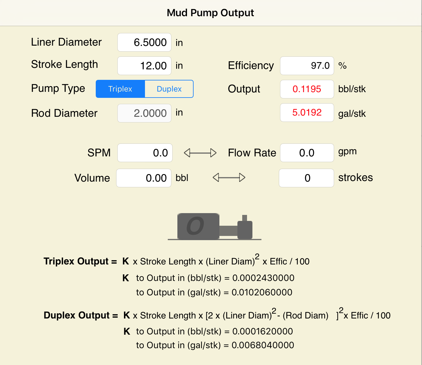
Pump Output per Stroke (PO): The calculator returns the pump output per stroke in barrels (bbl). However this can be automatically converted to other volume units (e.g. gallons or liters) via the pull-down menu.
A triplex mud (or slush) pump has three horizontal plungers (cylinders) driven off of one crankshaft. Triplex mud pumps are often used for oil drilling.

Oil and Gas drilling process - Pupm output for Triplex and Duplex pumpsTriplex Pump Formula 1 PO, bbl/stk = 0.000243 x ( in) E.xample: Determine the pump output, bbl/stk, at 100% efficiency for a 7" by 12". triplex pump: PO @ 100%,= 0.000243 x 7 x12 PO @ 100% = 0.142884bbl/stk Adjust the pump output for 95% efficiency: Decimal equivalent = 95 + 100 = 0.95 PO @ 95% = 0.142884bbl/stk x 0.95 PO @ 95% = 0.13574bbl/stk Formula 2 PO, gpm = [3(D x 0.7854)S]0.00411 x SPM where D = liner diameter, in. S = stroke length, in. SPM = strokes per minute Determine the pump output, gpm, for a 7" by 12". triplex pump at 80 strokes per minute: PO, gpm = [3(7 x 0.7854) 1210.00411 x 80 PO, gpm = 1385.4456 x 0.00411 x 80 PO = 455.5 gpm
Example:Duplex Pump Formula 1 0.000324 x (liner diameter, in) x ( stroke lengh, in) = ________ bbl/stk -0.000162 x (rod diameter, in) x ( stroke lengh, in) = ________ bbl/stk Pump out put @ 100% eff = ________bbl/stk Example: Determine the output, bbl/stk, of a 5 1/2" by 14" duplex pump at 100% efficiency. Rod diameter = 2.0": 0.000324 x 5.5 x 14 = 0.137214bbl/stk -0.000162 x 2.0 x 14 = 0.009072bbl/stk Pump output @ 100% eff. = 0.128142bbl/stk Adjust pump output for 85% efficiency: Decimal equivalent = 85 100 = 0.85 PO@85%)= 0.128142bbl/stk x 0.85 PO@ 85% = 0.10892bbl/stk Formula 2
PO. bbl/stk = 0.000162 x S[2(D) - d] where S = stroke length, in. D = liner diameter, in. d = rod diameter, in. Example: Determine the output, bbl/stk, of a 5 1/2". by 14". duplex pump @ 100% efficiency. Rod diameter = 2.0in.: PO@100%=0.000162 x 14 x [ 2 (5.5) - 2 ] PO @ 100%)= 0.000162 x 14 x 56.5 PO@ 100%)= 0.128142bbl/stk Adjust pump output for 85% efficiency: PO@85%,= 0.128142bb/stkx 0.85 PO@8.5%= 0.10892bbl/stk Metric calculation Pump output, liter/min = pump output. liter/stk x pump speed, spm. S.I. units calculation Pump output, m/min = pump output, liter/stk x pump speed, spm. Mud Pumps Mud pumps drive the mud around the drilling system. Depending on liner size availability they can be set up to provide high pressure and low flow rate, or low pressure and high flow rate. Analysis of the application and running the Drill Bits hydraulics program will indicate which liners to recommend. Finding the specification of the mud pumps allows flow rate to be calculated from pump stroke rate, SPM. Information requiredo Pump manufacturer o Number of pumps o Liner size and gallons per revolution Weight As a drill bit cutting structure wears more weight will be required to achieve the same RoP in a homogenous formation. PDC wear flats, worn inserts and worn milled tooth teeth will make the bit drill less efficiently. Increase weight in increments of 2,000lbs approx. In general, weight should be applied before excessive rotary speed so that the cutting structure maintains a significant depth of cut to stabilise the bit and prevent whirl. If downhole weight measurements are available they can be used in combination with surface measurements to gain a more accurate representation of what is happening in the well bore.
Single Acting Triplex pumps come with three cylinders and are commonly used for various applications requiring low to medium flow rates including mud pumping, cement pumping, salt water disposal, descaling, high pressure pumping, Frac pumping and pipeline systems for the Oil & Gas, Agriculture, Mining, Municipal and Manufacturing sectors. We have new, used and rebuilt API 674 triplex pumps of all leading manufacturers like Union, Gaso, Emsco, Apex and Wheatley.

Single Acting Triplex pumps come with three cylinders and are commonly used for various applications requiring low to medium flow rates including mud pumping, cement pumping, salt water disposal, descaling, high pressure pumping, Frac pumping and pipeline systems for the Oil & Gas, Agriculture, Mining, Municipal and Manufacturing sectors. We have new, used and rebuilt API 674 triplex pumps of all leading manufacturers like Union, Gaso, Emsco, Apex and Wheatley.

Pivotal to drilling and production, multiplex drilling pumps for sale have increased operational efficiency through the ability to ferry large volumes of fluid. At the heart of the quintuplex drilling pump developed by ShalePumps, lies a design that exploits the output of additional cylinders to curb pulsation variance.
Packed into physically smaller dimensions, the power packed quintuplex drilling pump assures a steady flow at the surface. With proven reliability, the quintuplex pump keeps the fluid in circulation, maintaining optimal pressure and volume, fetching debris effortlessly from the wellbore.
The featured quintuplex drilling pump combines structural superiority and engineering knowhow for enhanced life expectancy in continuous operations. Additionally, Measurement While Drilling (MWD) and Logging While Drilling (LWD) operations are substantially improved by the increased data transfer rate bandwidth.
The design accomplishes the added objective of extending life of downhole tools through operational precision of the quintuplex drilling pump. Improved rate of flow helps in cutting overall costs, dispensing with the need for many pumps. ShalePumps, possessing the technical expertise with an extensive range of proven solutions, takes great care to incorporate high quality components in every quintuplex drilling pump. The crankshafts, piston rods, liners, connecting rods, bearings etc are all of the highest quality. Each quintuplex drilling pump, despite the composition of high wear components, is guaranteed to offer longer continuous life.
ShalePumps is proud to bring the quintuplex design to a new level. Built to be smaller, lighter and smoother than any conventional triplex design. The addition of a fourth and fifth cylinder decreases pulsation variance to a minimal level. This increases accuracy and precision during LWD and MWD applications and increases the life expectancy of down-hole tools.

Since the NOV A1700-PT Triplex Mud Pump was built approximately 60 years ago, the industry has widely accepted the three cylinder or triplex style pump. Triplex mud pumps are manufactured worldwide, and many companies have emulated the original design and developed an improved form of the triplex pump in the past decade.
NOV A1700-PT Triplex Mud Pumps have many advantages they weight 30% less than a duplex of equal horsepower or kilowatts. The lighter weight parts are easier to handle and therefore easier to maintain. The other advantages include;They cost less to operate
One of the more important advantages of triplex over duplex pumps, is that they can move large volumes of mud at the higher pressure is required for modern deep hole drilling.
NOV A1700-PT Triplex Mud Pump is gradually phasing out duplex units. In a triplex pump, the pistons discharge mud only when they move forward in the liner. Then, when they moved back they draw in mud on the same side of the piston. Because of this, they are also called “single acting.” Single acting triplex pumps, pump mud at a relatively high speeds. NOV A1700-PT Triplex Mud Pump has three pistons each moving in its own liner. It also has three intake valves and three discharge valves. It also has a pulsation dampener in the discharge line.

In addition to selecting the proper suction pipe diameter and having adequate NPSHA, the submergence level and suction pipe configuration must be considered. Submergence level is the depth of the suction pipe inlet below the liquid surface. If an inadequate submergence level exists, an air vortex will form that extends from the liquid surface to the inlet of the suction pipe. This will introduce air into the system, resulting in either turbulent flow patterns or vapor locking of the pump. Amount of submergence required varies with velocity of the fluid. Fluid velocity is controlled by flow rate and pipe diameter. Refer to Figure 1. to determine submergence required based on fluid velocity (fluid velocity can be found in Friction Loss (Centrifugal Pumps Velocity Measured), in the column ‘‘V (ft/sec)’’).
If a system utilizes a 6-inch suction line with a flow rate of 600 gpm, suction-line velocities will be 6.6 fps and the line will therefore require approximately 3.5 feet of liquid surface above the suction-line entrance. Once the submergence level drops below 3.5 feet, an air vortex will form, causing air to enter the pump suction, resulting in a turbulent flow pattern and/or vapor lock.
In addition to proper line size and submergence level, a suction pipe should slope gradually upward from the source to the pump suction. This prevents air traps within the suction line. There should be a straight run prior to the pump entrance of at least two pipe diameters in length to reduce turbulence. A smooth-flowing valve should be installed in the suction line that will allow the pump to be isolated for maintenance and inspection. If a suction hose is used in lieu of hard piping, the hose must be noncollapsing. Refer to Figures 3 and 4 for examples of accepted piping practices.
Triplex mud pumps are often operated at speeds at which head in the suction tank is insufficient to maintain fluid against the piston face during the filling stroke. If fluid does not remain against the face, air is sucked in from behind the piston, causing a fluid void. If a void is formed, the piston strikes the fluid when the piston reverses direction during the pressure stroke. This causes a shock load that damages the triplex power end and fluid end and lowers expendable parts life. Supercharging pumps are used to accelerate fluid in the suction line of a triplex mud pump during the filling stroke, allowing fluid to maintain pace with the piston. A properly sized supercharging pump will accelerate fluid so that fluid voids and shock loads do not occur.
Triplex mud pumps normally have shock loads at speeds greater than 60 strokes per minute (spm) (when not supercharged). Without proper equipment, this would go unnoticed until the pump exceeded 80 strokes per minute, but meanwhile the shock load is damaging the pump. Supercharging requires an oversized pump with wide impellers to adequately react to rapid changes in flow required by the triplex mud pump. When sizing a centrifugal pump for a mud pump supercharging application, the pump should be sized for 1½ times the required flow rate. Therefore, if the triplex mud pump maximum flow rate is 600 gpm, the centrifugal pump should be sized for 900 gpm. High-speed piston and plunger pumps that stroke above 200 spm should be designed with a supercharging pump that produces 1¾ to 2 times the required flow rate.
Supercharging is one of the few applications in which the centrifugal pump does not have steady flow. The flow pulsates. Small impellers operating at 1750 rpm have a tendency to slip through the fluid when acceleration is needed. This is similar to car tires slipping on wet pavement. Even though it sometimes appears that the small impeller running at 1750 rpm is providing enough head, shock loading may be occurring. Supercharging pumps should have larger impellers running at either 1150 (60 cycles) or 1450 rpm (50 cycles) and should normally be sized to produce 85 feet of head at the triplex suction inlet. Supercharging pumps should be located as close to the supply tank as possible. Mounting supercharging pumps near the triplex and away from the supply tank transfers suction problems from the triplex to the centrifugal pump. If the centrifugal pump does not have a favorable supply with short suction run, it will have an insufficient supply to accelerate fluid.
Piping for supercharging pumps and triplex pump suctions should be oversized for the flow rate. Pipe should be sized so the change in line velocity during pulsations will not be over 1.5 ft/sec during the change from low flow rate to high flow rate during the triplex pulsation cycles.
Since the change in line velocity in 6-inch pipe is less than 1.5 ft/sec, this pipe size can be used for supercharging a triplex with an average flow of 600 gpm.
There are times when a single centrifugal pump will not meet the head requirements of an application. Two pumps can be operated in series to achieve the desired discharge head, in which the discharge of one pump feeds the suction of the second pump. The second pump boosts the head produced by the first. Therefore, if an application required 2900 gpm at 200 feet of head, one option would be to run two 10×8×14 pumps in series. Each pump could be configured with a 13-inch impeller to produce 2900 gpm at 100 feet of head. When operated in series, the pumps would produce 2900 gpm at 200 feet of head.
This type of configuration is most commonly used for extremely long discharge runs. When running pumps in series, it is important not to exceed flange safety ratings. Additionally, it is not required to place pumps within close proximity of each other. If an application had a 6-mile discharge line the first pump could be located at the supply source and the second pump could be located 3 miles away.
exists that requires high volume and low head and volume required is greater than can be produced by a single pump, two pumps are sometimes used in a parallel configuration to meet the demand. Two pumps that produce the same TDH can be configured so that each pump has an individual suction but both pumps feed into the same discharge line. If the pumps are identical, head in the discharge line is equal to that of the pumps, but the volume is double what a single pump can produce. However, two centrifugal pumps will never have the exact same discharge head, and as wear occurs one pump will produce less head than the other and the stronger pump will overpower the weaker pump and force fluid to backflow into the weaker pump. For this reason, parallel operation is not normally recommended.
Two pumps can be configured in parallel but only one pump is operated at a time, thus providing a primary and a backup pump. The two pumps are separated by a valve in each discharge line that prevents one pump from pumping through the other. This type of configuration is perfectly acceptable and, in crucial applications, encouraged.

This little calculator gives a barrels per stroke value of the Triplex pump being used at any efficiency. This little program is another tool in the mud engineer"s toolkit.

This approach works well but relying on a printed reference is not without the risk since the wrong value can still be selected from the fine print of a reference table, or the reference document can be damaged or lost (e.g., dropped in the mud pit) altogether.
So, let’s address the alternative approach of using simple mathematical formulas to determine the same information. Although the reliance on a single sheet of paper to obtain the needed value is avoided with this approach, the potential for human error or miscalculation remains, meaning regardless of the approach, great care in determining such values is prudent.
Once we have obtained the number of units we need, we can convert that value into a familiar unit that we’re comfortable working with. For example, we may use a formula to determine the volume of a borehole to be 100 cubic feet (ft3), but we want to know the answer in gallons. Since we know that every cubic foot contains 7.48 gallons, we can easily convert that borehole volume to 748 gallons.
We want to know the volume of material (filter pack sand, cement grout, etc.) that is to be placed in the annulus to assure the annular void has been properly and completely filled (Figure 1). The conceptual diagram showing the variables used for calculating an annular void is shown in Figure 2, and the formula for the annular volume calculation is:
In this calculation, the “d” value is the diameter of the casing or pipe diameter, and the “D” value is the borehole diameter (Figure 2). The sump area below the base of the casing has only one diameter in the open borehole, so the “d” value is omitted, and the formula just becomes:
If excessive hydraulic pressures are exerted on a well casing, it will collapse. We generally know the collapse strength of the well casing from the casing supplier or from standard references such as the charts in American Water Works Association Standard A100. The hydraulic pressures applied to the outside of the well casing depend on the density of the liquid and the depth of submergence (Figure 1). Applying the fluid density (measured in the field) and depth (Figure 2), the formula for hydraulic pressure head calculation is:
The hydraulic head formula is applicable to the hydraulic pressure head for any liquid, but we most commonly use this calculation during cement seal installation, since cement grout is generally the heaviest liquid being introduced to the annulus during well construction.
The intermediate casing can be sealed using the pressure grouting technique (Figure 3) to pump cement slurry down through the drill pipe and out to the annulus through a float shoe (a drillable check valve connected to the base of the casing). The inside of the intermediate casing is kept full of water during the cement placement to equilibrate hydraulic pressures inside and outside the casing. After the intermediate casing is sealed with the pressure grouted cement, the float shoe can be drilled out and the borehole advanced for installation of the screen and filter pack in the lower part of the well.
The buoyancy calculation is more of a conceptual comparison than a pure mathematical formula. This analysis involves some visualization be made on the part of the groundwater professional.
The pounds per linear foot of any casing or screen material is generally provided by the casing or screen supplier, but the variables in Figure 2 can be applied to the following formula to estimate the casing string weight:
This string weight formula is applicable to blank casing only, and material suppliers should be consulted for detailed pounds per linear foot values and safe hang weights for well screens. This formula is broadly applicable, however, and handy for a quick double check on material weights.
There are several calculations that are commonly applied by drilling fluid engineers (mud engineers) to determine the time period required for the fluid to move from one location in the borehole to another. Some of the more common equations are described below.
The uphole velocity calculation provides a determination of the speed at which the drilling mud will flow as it moves up the borehole. For direct air rotary or reverse circulation drilling methods, the uphole velocity is high, so this calculation is generally applicable only for the direct mud-rotary drilling method. The formula for uphole velocity is:
Notice the uphole velocity formula is similar to the annular volume formula in that both those calculations use the factor (D2 – d2) to address the cross-sectional area of the annulus. However, the constants in these two formulas are different (0.005454 versus 24.51), which can be confusing. Keep in mind, however, that the constants primarily just provide unit conversions.
If we do the same thing by first calculating the annular volume and then applying the 10 gpm flow rate to it, we will get an identical result of 3.83 ft/minute. The uphole velocity formula provides a more direct method to determine uphole velocity, whereas the annular volume formula provides a more direct method to calculate the annular volume.
We can calculate the bottoms-up time by using the uphole velocity formula with the borehole depth and drilling mud flow rate plugged in, but that flow rate is being generated by the mud pump, and positive displacement mud pumps (duplex or triplex) are almost never equipped with a flow meter. To determine the flow coming from the mud pump, we can use the formulas:
Remember the strokes are counted in both the forward and backward directions on a duplex pump, but only in the forward direction on a triplex pump. Drillers often have reference charts that provide oilfield barrels per stroke (bbl/stroke), which can be converted to gpm by timing the strokes per minute and converting barrels to gallons (1 barrel = 42 gallons).
A specified volume of drilling fluids (called a pill) can be circulated to a particular depth interval within the borehole (called spotting), so that the additives in the pill of drilling mud can address the borehole problem at a particular depth of the borehole. This is shown in Figure 6(C).
The calculation for time required to spot a pill of drillingfluid involves determining the pumping time (at the calculated flow rate) required to displace the fluid so that the drilling mud additives are located adjacent to the problematic interval. This approach is used by mud engineers to address problems such as lost circulation or stuck drill pipe.
The formulas and calculations provided in this column and elsewhere provide important tools for us to quantify the variables we need for water well design and construction. However, it is important to remember that “doing the math” is not a replacement for applying professional knowledge and consideration to determine whether the mathematical result makes common sense.


 8613371530291