
2 mud pump hose free sample

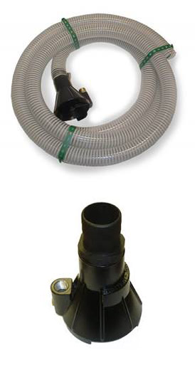
The 2 inch quick connect 50 ft. discharge hose from Allegro is made to move water / sludge that may contain sand, solids and leaves. The hose fits the Allegro dewatering and sludge pumps,made from tough PVC. Collapsible and can be rolled tightly for compact storage.
A fire hose quick-connect design attaches the 9404-50 Allegro hose securely to the Allegro 9404-01 Deluxe Dewatering pump, 9404-02 Standard pump, 9404-03 Low Water pump, and the 9404-04 Sludge pumps.
505 mud pump hose products are offered for sale by suppliers on Alibaba.comAbout 51% % of these are rubber hoses, 19%% are pumps, and 1%% are mud pump.
A wide variety of mud pump hose options are available to you, such as 1 year, not available and 2 years.You can also choose from new, mud pump hose,as well as from energy & mining, construction works , and machinery repair shops mud pump hose,and whether mud pump hose is 1.5 years, or unavailable.

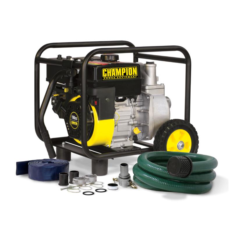
The Champion Power Equipment 100113 2-inch Semi-Trash Gas-Powered Water Transfer Pump with Hose and Wheel Kit comes with everything you need to start pumping (just add oil and gas). Capable of passing solid waste up to 9/16 of an inch in diameter, this transfer pump is the perfect solution for moving water quickly and efficiently.
This lightweight and portable transfer pump has a maximum delivery volume of 158 gallons per minute and is capable of passing solid waste up to 9/16 inch in diameter. With a 2-inch NPT inlet and NPT 2-inch outlet, this unit has a total head of 98 feet and a suction head of 26 feet.
The complete hose kit provides everything you need to get your pump into action, including a 12-foot intake hose, a 20-foot discharge hose, cam action quick coupler, intake strainer, hose clamps, outlet hose adapter, outlet hose fitting and teflon tape.
The shaft seals are made of sturdy silicone carbide. The lightweight and durable steel frame along with this unit’s compact design make it convenient to store your pump until the next time you need it.
This water transfer pump is EPA certified. Buy with confidence - Champion Support and our nationwide network of service centers will back your purchase up with a 2-year limited warranty and FREE lifetime technical support.

Sludge Sucker uses a high pressure water stream (1000-4000 PSI) to suck the sludge off the bottom of pits or tanks and eject it through a 1-1/2" (15 FT. long) hose to a disposal tank.
The Sludge Pump is a great tool for cleaning up water and slurries. Simply attach the pressure line from a portable power washer or car wash bay. The water flowing through the high pressure nozzle creates a powerful venturi suction that vacuums up slurry solutions. Debris as large as 3/4" will pass through the casting and out the discharge hose.

Afghanistan, Africa, Alaska/Hawaii, Argentina, Armenia, Azerbaijan Republic, Bahrain, Bangladesh, Barbados, Bermuda, Bhutan, Bolivia, Brunei Darussalam, Cambodia, Canada, Central America and Caribbean, Chile, Colombia, Ecuador, Falkland Islands (Islas Malvinas), French Guiana, French Polynesia, Georgia, Greenland, Guadeloupe, Guyana, Hong Kong, India, Indonesia, Iraq, Israel, Jordan, Kazakhstan, Kuwait, Kyrgyzstan, Laos, Lebanon, Libya, Macau, Malaysia, Maldives, Martinique, Middle East, Mongolia, Nepal, New Caledonia, Oceania, Oman, Pakistan, Paraguay, Peru, Philippines, Qatar, Reunion, Russian Federation, Saint Pierre and Miquelon, Saudi Arabia, Singapore, South Korea, Southeast Asia, Sri Lanka, Suriname, Taiwan, Tajikistan, Thailand, Turkey, Turkmenistan, Ukraine, United Arab Emirates, Uzbekistan, Venezuela, Vietnam, Yemen

Mechanical pumps serve in a wide range of applications such as pumping water from wells, aquarium filtering, pond filtering and aeration, in the car industry for water-cooling and fuel injection, in the energy industry for pumping oil and natural gas or for operating cooling towers and other components of heating, ventilation and air conditioning systems. In the medical industry, pumps are used for biochemical processes in developing and manufacturing medicine, and as artificial replacements for body parts, in particular the artificial heart and penile prosthesis.
When a pump contains two or more pump mechanisms with fluid being directed to flow through them in series, it is called a multi-stage pump. Terms such as two-stage or double-stage may be used to specifically describe the number of stages. A pump that does not fit this description is simply a single-stage pump in contrast.
In biology, many different types of chemical and biomechanical pumps have evolved; biomimicry is sometimes used in developing new types of mechanical pumps.
Pumps can be classified by their method of displacement into positive-displacement pumps, impulse pumps, velocity pumps, gravity pumps, steam pumps and valveless pumps. There are three basic types of pumps: positive-displacement, centrifugal and axial-flow pumps. In centrifugal pumps the direction of flow of the fluid changes by ninety degrees as it flows over an impeller, while in axial flow pumps the direction of flow is unchanged.
Some positive-displacement pumps use an expanding cavity on the suction side and a decreasing cavity on the discharge side. Liquid flows into the pump as the cavity on the suction side expands and the liquid flows out of the discharge as the cavity collapses. The volume is constant through each cycle of operation.
Positive-displacement pumps, unlike centrifugal, can theoretically produce the same flow at a given speed (rpm) no matter what the discharge pressure. Thus, positive-displacement pumps are constant flow machines. However, a slight increase in internal leakage as the pressure increases prevents a truly constant flow rate.
A positive-displacement pump must not operate against a closed valve on the discharge side of the pump, because it has no shutoff head like centrifugal pumps. A positive-displacement pump operating against a closed discharge valve continues to produce flow and the pressure in the discharge line increases until the line bursts, the pump is severely damaged, or both.
A relief or safety valve on the discharge side of the positive-displacement pump is therefore necessary. The relief valve can be internal or external. The pump manufacturer normally has the option to supply internal relief or safety valves. The internal valve is usually used only as a safety precaution. An external relief valve in the discharge line, with a return line back to the suction line or supply tank provides increased safety.
Rotary-type positive displacement: internal or external gear pump, screw pump, lobe pump, shuttle block, flexible vane or sliding vane, circumferential piston, flexible impeller, helical twisted roots (e.g. the Wendelkolben pump) or liquid-ring pumps
Drawbacks: The nature of the pump requires very close clearances between the rotating pump and the outer edge, making it rotate at a slow, steady speed. If rotary pumps are operated at high speeds, the fluids cause erosion, which eventually causes enlarged clearances that liquid can pass through, which reduces efficiency.
Hollow disk pumps (also known as eccentric disc pumps or Hollow rotary disc pumps), similar to scroll compressors, these have a cylindrical rotor encased in a circular housing. As the rotor orbits and rotates to some degree, it traps fluid between the rotor and the casing, drawing the fluid through the pump. It is used for highly viscous fluids like petroleum-derived products, and it can also support high pressures of up to 290 psi.
Vibratory pumps or vibration pumps are similar to linear compressors, having the same operating principle. They work by using a spring-loaded piston with an electromagnet connected to AC current through a diode. The spring-loaded piston is the only moving part, and it is placed in the center of the electromagnet. During the positive cycle of the AC current, the diode allows energy to pass through the electromagnet, generating a magnetic field that moves the piston backwards, compressing the spring, and generating suction. During the negative cycle of the AC current, the diode blocks current flow to the electromagnet, letting the spring uncompress, moving the piston forward, and pumping the fluid and generating pressure, like a reciprocating pump. Due to its low cost, it is widely used in inexpensive espresso machines. However, vibratory pumps cannot be operated for more than one minute, as they generate large amounts of heat. Linear compressors do not have this problem, as they can be cooled by the working fluid (which is often a refrigerant).
Reciprocating pumps move the fluid using one or more oscillating pistons, plungers, or membranes (diaphragms), while valves restrict fluid motion to the desired direction. In order for suction to take place, the pump must first pull the plunger in an outward motion to decrease pressure in the chamber. Once the plunger pushes back, it will increase the chamber pressure and the inward pressure of the plunger will then open the discharge valve and release the fluid into the delivery pipe at constant flow rate and increased pressure.
Pumps in this category range from simplex, with one cylinder, to in some cases quad (four) cylinders, or more. Many reciprocating-type pumps are duplex (two) or triplex (three) cylinder. They can be either single-acting with suction during one direction of piston motion and discharge on the other, or double-acting with suction and discharge in both directions. The pumps can be powered manually, by air or steam, or by a belt driven by an engine. This type of pump was used extensively in the 19th century—in the early days of steam propulsion—as boiler feed water pumps. Now reciprocating pumps typically pump highly viscous fluids like concrete and heavy oils, and serve in special applications that demand low flow rates against high resistance. Reciprocating hand pumps were widely used to pump water from wells. Common bicycle pumps and foot pumps for inflation use reciprocating action.
These positive-displacement pumps have an expanding cavity on the suction side and a decreasing cavity on the discharge side. Liquid flows into the pumps as the cavity on the suction side expands and the liquid flows out of the discharge as the cavity collapses. The volume is constant given each cycle of operation and the pump"s volumetric efficiency can be achieved through routine maintenance and inspection of its valves.
This is the simplest form of rotary positive-displacement pumps. It consists of two meshed gears that rotate in a closely fitted casing. The tooth spaces trap fluid and force it around the outer periphery. The fluid does not travel back on the meshed part, because the teeth mesh closely in the center. Gear pumps see wide use in car engine oil pumps and in various hydraulic power packs.
A screw pump is a more complicated type of rotary pump that uses two or three screws with opposing thread — e.g., one screw turns clockwise and the other counterclockwise. The screws are mounted on parallel shafts that have gears that mesh so the shafts turn together and everything stays in place. The screws turn on the shafts and drive fluid through the pump. As with other forms of rotary pumps, the clearance between moving parts and the pump"s casing is minimal.
Widely used for pumping difficult materials, such as sewage sludge contaminated with large particles, a progressing cavity pump consists of a helical rotor, about ten times as long as its width. This can be visualized as a central core of diameter x with, typically, a curved spiral wound around of thickness half x, though in reality it is manufactured in a single casting. This shaft fits inside a heavy-duty rubber sleeve, of wall thickness also typically x. As the shaft rotates, the rotor gradually forces fluid up the rubber sleeve. Such pumps can develop very high pressure at low volumes.
Named after the Roots brothers who invented it, this lobe pump displaces the fluid trapped between two long helical rotors, each fitted into the other when perpendicular at 90°, rotating inside a triangular shaped sealing line configuration, both at the point of suction and at the point of discharge. This design produces a continuous flow with equal volume and no vortex. It can work at low pulsation rates, and offers gentle performance that some applications require.
A peristaltic pump is a type of positive-displacement pump. It contains fluid within a flexible tube fitted inside a circular pump casing (though linear peristaltic pumps have been made). A number of rollers, shoes, or wipers attached to a rotor compresses the flexible tube. As the rotor turns, the part of the tube under compression closes (or occludes), forcing the fluid through the tube. Additionally, when the tube opens to its natural state after the passing of the cam it draws (restitution) fluid into the pump. This process is called peristalsis and is used in many biological systems such as the gastrointestinal tract.
Efficiency and common problems: With only one cylinder in plunger pumps, the fluid flow varies between maximum flow when the plunger moves through the middle positions, and zero flow when the plunger is at the end positions. A lot of energy is wasted when the fluid is accelerated in the piping system. Vibration and
Triplex plunger pumps use three plungers, which reduces the pulsation of single reciprocating plunger pumps. Adding a pulsation dampener on the pump outlet can further smooth the pump ripple, or ripple graph of a pump transducer. The dynamic relationship of the high-pressure fluid and plunger generally requires high-quality plunger seals. Plunger pumps with a larger number of plungers have the benefit of increased flow, or smoother flow without a pulsation damper. The increase in moving parts and crankshaft load is one drawback.
Car washes often use these triplex-style plunger pumps (perhaps without pulsation dampers). In 1968, William Bruggeman reduced the size of the triplex pump and increased the lifespan so that car washes could use equipment with smaller footprints. Durable high-pressure seals, low-pressure seals and oil seals, hardened crankshafts, hardened connecting rods, thick ceramic plungers and heavier duty ball and roller bearings improve reliability in triplex pumps. Triplex pumps now are in a myriad of markets across the world.
Triplex pumps with shorter lifetimes are commonplace to the home user. A person who uses a home pressure washer for 10 hours a year may be satisfied with a pump that lasts 100 hours between rebuilds. Industrial-grade or continuous duty triplex pumps on the other end of the quality spectrum may run for as much as 2,080 hours a year.
The oil and gas drilling industry uses massive semi trailer-transported triplex pumps called mud pumps to pump drilling mud, which cools the drill bit and carries the cuttings back to the surface.
One modern application of positive-displacement pumps is compressed-air-powered double-diaphragm pumps. Run on compressed air, these pumps are intrinsically safe by design, although all manufacturers offer ATEX certified models to comply with industry regulation. These pumps are relatively inexpensive and can perform a wide variety of duties, from pumping water out of bunds to pumping hydrochloric acid from secure storage (dependent on how the pump is manufactured – elastomers / body construction). These double-diaphragm pumps can handle viscous fluids and abrasive materials with a gentle pumping process ideal for transporting shear-sensitive media.
Devised in China as chain pumps over 1000 years ago, these pumps can be made from very simple materials: A rope, a wheel and a pipe are sufficient to make a simple rope pump. Rope pump efficiency has been studied by grassroots organizations and the techniques for making and running them have been continuously improved.
Impulse pumps use pressure created by gas (usually air). In some impulse pumps the gas trapped in the liquid (usually water), is released and accumulated somewhere in the pump, creating a pressure that can push part of the liquid upwards.
Instead of a gas accumulation and releasing cycle, the pressure can be created by burning of hydrocarbons. Such combustion driven pumps directly transmit the impulse from a combustion event through the actuation membrane to the pump fluid. In order to allow this direct transmission, the pump needs to be almost entirely made of an elastomer (e.g. silicone rubber). Hence, the combustion causes the membrane to expand and thereby pumps the fluid out of the adjacent pumping chamber. The first combustion-driven soft pump was developed by ETH Zurich.
It takes in water at relatively low pressure and high flow-rate and outputs water at a higher hydraulic-head and lower flow-rate. The device uses the water hammer effect to develop pressure that lifts a portion of the input water that powers the pump to a point higher than where the water started.
The hydraulic ram is sometimes used in remote areas, where there is both a source of low-head hydropower, and a need for pumping water to a destination higher in elevation than the source. In this situation, the ram is often useful, since it requires no outside source of power other than the kinetic energy of flowing water.
Rotodynamic pumps (or dynamic pumps) are a type of velocity pump in which kinetic energy is added to the fluid by increasing the flow velocity. This increase in energy is converted to a gain in potential energy (pressure) when the velocity is reduced prior to or as the flow exits the pump into the discharge pipe. This conversion of kinetic energy to pressure is explained by the
A practical difference between dynamic and positive-displacement pumps is how they operate under closed valve conditions. Positive-displacement pumps physically displace fluid, so closing a valve downstream of a positive-displacement pump produces a continual pressure build up that can cause mechanical failure of pipeline or pump. Dynamic pumps differ in that they can be safely operated under closed valve conditions (for short periods of time).
Such a pump is also referred to as a centrifugal pump. The fluid enters along the axis or center, is accelerated by the impeller and exits at right angles to the shaft (radially); an example is the centrifugal fan, which is commonly used to implement a vacuum cleaner. Another type of radial-flow pump is a vortex pump. The liquid in them moves in tangential direction around the working wheel. The conversion from the mechanical energy of motor into the potential energy of flow comes by means of multiple whirls, which are excited by the impeller in the working channel of the pump. Generally, a radial-flow pump operates at higher pressures and lower flow rates than an axial- or a mixed-flow pump.
These are also referred to as All fluid pumps. The fluid is pushed outward or inward to move fluid axially. They operate at much lower pressures and higher flow rates than radial-flow (centrifugal) pumps. Axial-flow pumps cannot be run up to speed without special precaution. If at a low flow rate, the total head rise and high torque associated with this pipe would mean that the starting torque would have to become a function of acceleration for the whole mass of liquid in the pipe system. If there is a large amount of fluid in the system, accelerate the pump slowly.
Mixed-flow pumps function as a compromise between radial and axial-flow pumps. The fluid experiences both radial acceleration and lift and exits the impeller somewhere between 0 and 90 degrees from the axial direction. As a consequence mixed-flow pumps operate at higher pressures than axial-flow pumps while delivering higher discharges than radial-flow pumps. The exit angle of the flow dictates the pressure head-discharge characteristic in relation to radial and mixed-flow.
Regenerative turbine pump rotor and housing, 1⁄3 horsepower (0.25 kW). 85 millimetres (3.3 in) diameter impeller rotates counter-clockwise. Left: inlet, right: outlet. .4 millimetres (0.016 in) thick vanes on 4 millimetres (0.16 in) centers
Also known as drag, friction, peripheral, traction, turbulence, or vortex pumps, regenerative turbine pumps are class of rotodynamic pump that operates at high head pressures, typically 4–20 bars (4.1–20.4 kgf/cm2; 58–290 psi).
The pump has an impeller with a number of vanes or paddles which spins in a cavity. The suction port and pressure ports are located at the perimeter of the cavity and are isolated by a barrier called a stripper, which allows only the tip channel (fluid between the blades) to recirculate, and forces any fluid in the side channel (fluid in the cavity outside of the blades) through the pressure port. In a regenerative turbine pump, as fluid spirals repeatedly from a vane into the side channel and back to the next vane, kinetic energy is imparted to the periphery,
As regenerative turbine pumps cannot become vapor locked, they are commonly applied to volatile, hot, or cryogenic fluid transport. However, as tolerances are typically tight, they are vulnerable to solids or particles causing jamming or rapid wear. Efficiency is typically low, and pressure and power consumption typically decrease with flow. Additionally, pumping direction can be reversed by reversing direction of spin.
Steam pumps have been for a long time mainly of historical interest. They include any type of pump powered by a steam engine and also pistonless pumps such as Thomas Savery"s or the Pulsometer steam pump.
Recently there has been a resurgence of interest in low power solar steam pumps for use in smallholder irrigation in developing countries. Previously small steam engines have not been viable because of escalating inefficiencies as vapour engines decrease in size. However the use of modern engineering materials coupled with alternative engine configurations has meant that these types of system are now a cost-effective opportunity.
Valveless pumping assists in fluid transport in various biomedical and engineering systems. In a valveless pumping system, no valves (or physical occlusions) are present to regulate the flow direction. The fluid pumping efficiency of a valveless system, however, is not necessarily lower than that having valves. In fact, many fluid-dynamical systems in nature and engineering more or less rely upon valveless pumping to transport the working fluids therein. For instance, blood circulation in the cardiovascular system is maintained to some extent even when the heart"s valves fail. Meanwhile, the embryonic vertebrate heart begins pumping blood long before the development of discernible chambers and valves. Similar to blood circulation in one direction, bird respiratory systems pump air in one direction in rigid lungs, but without any physiological valve. In microfluidics, valveless impedance pumps have been fabricated, and are expected to be particularly suitable for handling sensitive biofluids. Ink jet printers operating on the piezoelectric transducer principle also use valveless pumping. The pump chamber is emptied through the printing jet due to reduced flow impedance in that direction and refilled by capillary action.
Examining pump repair records and mean time between failures (MTBF) is of great importance to responsible and conscientious pump users. In view of that fact, the preface to the 2006 Pump User"s Handbook alludes to "pump failure" statistics. For the sake of convenience, these failure statistics often are translated into MTBF (in this case, installed life before failure).
In early 2005, Gordon Buck, John Crane Inc.’s chief engineer for field operations in Baton Rouge, Louisiana, examined the repair records for a number of refinery and chemical plants to obtain meaningful reliability data for centrifugal pumps. A total of 15 operating plants having nearly 15,000 pumps were included in the survey. The smallest of these plants had about 100 pumps; several plants had over 2000. All facilities were located in the United States. In addition, considered as "new", others as "renewed" and still others as "established". Many of these plants—but not all—had an alliance arrangement with John Crane. In some cases, the alliance contract included having a John Crane Inc. technician or engineer on-site to coordinate various aspects of the program.
Not all plants are refineries, however, and different results occur elsewhere. In chemical plants, pumps have historically been "throw-away" items as chemical attack limits life. Things have improved in recent years, but the somewhat restricted space available in "old" DIN and ASME-standardized stuffing boxes places limits on the type of seal that fits. Unless the pump user upgrades the seal chamber, the pump only accommodates more compact and simple versions. Without this upgrading, lifetimes in chemical installations are generally around 50 to 60 percent of the refinery values.
Unscheduled maintenance is often one of the most significant costs of ownership, and failures of mechanical seals and bearings are among the major causes. Keep in mind the potential value of selecting pumps that cost more initially, but last much longer between repairs. The MTBF of a better pump may be one to four years longer than that of its non-upgraded counterpart. Consider that published average values of avoided pump failures range from US$2600 to US$12,000. This does not include lost opportunity costs. One pump fire occurs per 1000 failures. Having fewer pump failures means having fewer destructive pump fires.
As has been noted, a typical pump failure, based on actual year 2002 reports, costs US$5,000 on average. This includes costs for material, parts, labor and overhead. Extending a pump"s MTBF from 12 to 18 months would save US$1,667 per year — which might be greater than the cost to upgrade the centrifugal pump"s reliability.
Pumps are used throughout society for a variety of purposes. Early applications includes the use of the windmill or watermill to pump water. Today, the pump is used for irrigation, water supply, gasoline supply, air conditioning systems, refrigeration (usually called a compressor), chemical movement, sewage movement, flood control, marine services, etc.
Because of the wide variety of applications, pumps have a plethora of shapes and sizes: from very large to very small, from handling gas to handling liquid, from high pressure to low pressure, and from high volume to low volume.
Typically, a liquid pump can"t simply draw air. The feed line of the pump and the internal body surrounding the pumping mechanism must first be filled with the liquid that requires pumping: An operator must introduce liquid into the system to initiate the pumping. This is called priming the pump. Loss of prime is usually due to ingestion of air into the pump. The clearances and displacement ratios in pumps for liquids, whether thin or more viscous, usually cannot displace air due to its compressibility. This is the case with most velocity (rotodynamic) pumps — for example, centrifugal pumps. For such pumps, the position of the pump should always be lower than the suction point, if not the pump should be manually filled with liquid or a secondary pump should be used until all air is removed from the suction line and the pump casing.
Positive–displacement pumps, however, tend to have sufficiently tight sealing between the moving parts and the casing or housing of the pump that they can be described as self-priming. Such pumps can also serve as priming pumps, so-called when they are used to fulfill that need for other pumps in lieu of action taken by a human operator.
One sort of pump once common worldwide was a hand-powered water pump, or "pitcher pump". It was commonly installed over community water wells in the days before piped water supplies.
In parts of the British Isles, it was often called the parish pump. Though such community pumps are no longer common, people still used the expression parish pump to describe a place or forum where matters of local interest are discussed.
Because water from pitcher pumps is drawn directly from the soil, it is more prone to contamination. If such water is not filtered and purified, consumption of it might lead to gastrointestinal or other water-borne diseases. A notorious case is the 1854 Broad Street cholera outbreak. At the time it was not known how cholera was transmitted, but physician John Snow suspected contaminated water and had the handle of the public pump he suspected removed; the outbreak then subsided.
Modern hand-operated community pumps are considered the most sustainable low-cost option for safe water supply in resource-poor settings, often in rural areas in developing countries. A hand pump opens access to deeper groundwater that is often not polluted and also improves the safety of a well by protecting the water source from contaminated buckets. Pumps such as the Afridev pump are designed to be cheap to build and install, and easy to maintain with simple parts. However, scarcity of spare parts for these type of pumps in some regions of Africa has diminished their utility for these areas.
Multiphase pumping applications, also referred to as tri-phase, have grown due to increased oil drilling activity. In addition, the economics of multiphase production is attractive to upstream operations as it leads to simpler, smaller in-field installations, reduced equipment costs and improved production rates. In essence, the multiphase pump can accommodate all fluid stream properties with one piece of equipment, which has a smaller footprint. Often, two smaller multiphase pumps are installed in series rather than having just one massive pump.
A rotodynamic pump with one single shaft that requires two mechanical seals, this pump uses an open-type axial impeller. It is often called a Poseidon pump, and can be described as a cross between an axial compressor and a centrifugal pump.
The twin-screw pump is constructed of two inter-meshing screws that move the pumped fluid. Twin screw pumps are often used when pumping conditions contain high gas volume fractions and fluctuating inlet conditions. Four mechanical seals are required to seal the two shafts.
These pumps are basically multistage centrifugal pumps and are widely used in oil well applications as a method for artificial lift. These pumps are usually specified when the pumped fluid is mainly liquid.
A buffer tank is often installed upstream of the pump suction nozzle in case of a slug flow. The buffer tank breaks the energy of the liquid slug, smooths any fluctuations in the incoming flow and acts as a sand trap.
As the name indicates, multiphase pumps and their mechanical seals can encounter a large variation in service conditions such as changing process fluid composition, temperature variations, high and low operating pressures and exposure to abrasive/erosive media. The challenge is selecting the appropriate mechanical seal arrangement and support system to ensure maximized seal life and its overall effectiveness.
Pumps are commonly rated by horsepower, volumetric flow rate, outlet pressure in metres (or feet) of head, inlet suction in suction feet (or metres) of head.
From an initial design point of view, engineers often use a quantity termed the specific speed to identify the most suitable pump type for a particular combination of flow rate and head.
The power imparted into a fluid increases the energy of the fluid per unit volume. Thus the power relationship is between the conversion of the mechanical energy of the pump mechanism and the fluid elements within the pump. In general, this is governed by a series of simultaneous differential equations, known as the Navier–Stokes equations. However a more simple equation relating only the different energies in the fluid, known as Bernoulli"s equation can be used. Hence the power, P, required by the pump:
where Δp is the change in total pressure between the inlet and outlet (in Pa), and Q, the volume flow-rate of the fluid is given in m3/s. The total pressure may have gravitational, static pressure and kinetic energy components; i.e. energy is distributed between change in the fluid"s gravitational potential energy (going up or down hill), change in velocity, or change in static pressure. η is the pump efficiency, and may be given by the manufacturer"s information, such as in the form of a pump curve, and is typically derived from either fluid dynamics simulation (i.e. solutions to the Navier–Stokes for the particular pump geometry), or by testing. The efficiency of the pump depends upon the pump"s configuration and operating conditions (such as rotational speed, fluid density and viscosity etc.)
For a typical "pumping" configuration, the work is imparted on the fluid, and is thus positive. For the fluid imparting the work on the pump (i.e. a turbine), the work is negative. Power required to drive the pump is determined by dividing the output power by the pump efficiency. Furthermore, this definition encompasses pumps with no moving parts, such as a siphon.
Pump efficiency is defined as the ratio of the power imparted on the fluid by the pump in relation to the power supplied to drive the pump. Its value is not fixed for a given pump, efficiency is a function of the discharge and therefore also operating head. For centrifugal pumps, the efficiency tends to increase with flow rate up to a point midway through the operating range (peak efficiency or Best Efficiency Point (BEP) ) and then declines as flow rates rise further. Pump performance data such as this is usually supplied by the manufacturer before pump selection. Pump efficiencies tend to decline over time due to wear (e.g. increasing clearances as impellers reduce in size).
When a system includes a centrifugal pump, an important design issue is matching the head loss-flow characteristic with the pump so that it operates at or close to the point of its maximum efficiency.
Most large pumps have a minimum flow requirement below which the pump may be damaged by overheating, impeller wear, vibration, seal failure, drive shaft damage or poor performance.
The simplest minimum flow system is a pipe running from the pump discharge line back to the suction line. This line is fitted with an orifice plate sized to allow the pump minimum flow to pass.
A more sophisticated, but more costly, system (see diagram) comprises a flow measuring device (FE) in the pump discharge which provides a signal into a flow controller (FIC) which actuates a flow control valve (FCV) in the recycle line. If the measured flow exceeds the minimum flow then the FCV is closed. If the measured flow falls below the minimum flow the FCV opens to maintain the minimum flowrate.
As the fluids are recycled the kinetic energy of the pump increases the temperature of the fluid. For many pumps this added heat energy is dissipated through the pipework. However, for large industrial pumps, such as oil pipeline pumps, a recycle cooler is provided in the recycle line to cool the fluids to the normal suction temperature.oil refinery, oil terminal, or offshore installation.
Engineering Sciences Data Unit (2007). "Radial, mixed and axial flow pumps. Introduction" (PDF). Archived from the original (PDF) on 2014-03-08. Retrieved 2017-08-18.
Tanzania water Archived 2012-03-31 at the Wayback Machine blog – example of grassroots researcher telling about his study and work with the rope pump in Africa.
C.M. Schumacher, M. Loepfe, R. Fuhrer, R.N. Grass, and W.J. Stark, "3D printed lost-wax casted soft silicone monoblocks enable heart-inspired pumping by internal combustion," RSC Advances, Vol. 4, pp. 16039–16042, 2014.
"Radial, mixed and axial flow pumps" (PDF). Institution of Diploma Marine Engineers, Bangladesh. June 2003. Archived from the original (PDF) on 2014-03-08. Retrieved 2017-08-18.
Quail F, Scanlon T, Stickland M (2011-01-11). "Design optimisation of a regenerative pump using numerical and experimental techniques" (PDF). International Journal of Numerical Methods for Heat & Fluid Flow. 21: 95–111. doi:10.1108/09615531111095094. Retrieved 2021-07-21.
Rajmane, M. Satish; Kallurkar, S.P. (May 2015). "CFD Analysis of Domestic Centrifugal Pump for Performance Enhancement". International Research Journal of Engineering and Technology. 02 / #02. Retrieved 30 April 2021.
Wasser, Goodenberger, Jim and Bob (November 1993). "Extended Life, Zero Emissions Seal for Process Pumps". John Crane Technical Report. Routledge. TRP 28017.
Donald Routledge Hill, "Mechanical Engineering in the Medieval Near East", cf. Donald Hill, Mechanical Engineering Archived 25 December 2007 at the Wayback Machine)
Australian Pump Manufacturers" Association. Australian Pump Technical Handbook, 3rd edition. Canberra: Australian Pump Manufacturers" Association, 1987. ISBN 0-7316-7043-4.

A peristaltic pump, also commonly known as a roller pump, is a type of positive displacement pump used for pumping a variety of fluids. The fluid is contained in a flexible tube fitted inside a circular pump casing. Most peristaltic pumps work through rotary motion, though linear peristaltic pumps have also been made. The rotor has a number of "wipers" or "rollers" attached to its external circumference, which compress the flexible tube as they rotate by. The part of the tube under compression is closed, forcing the fluid to move through the tube. Additionally, as the tube opens to its natural state after the rollers pass, more fluid is drawn into the tube. This process is called peristalsis and is used in many biological systems such as the gastrointestinal tract. Typically, there will be two or more rollers compressing the tube, trapping a body of fluid between them. The body of fluid is transported through the tube, toward the pump outlet. Peristaltic pumps may run continuously, or they may be indexed through partial revolutions to deliver smaller amounts of fluid.
A form of peristaltic pump was described in The Mechanics Magazine in 1845. The pump used a leather hose which did not need to self-open when released by the rollers, instead relying on the incoming water having sufficient pressure to fill the open inlet end on each cycle.Rufus Porter and J.D. Bradley in 1855 (U.S. Patent number 12753)blood transfusions. It was developed by heart surgeon Dr. Michael DeBakeycardiopulmonary bypass
Peristaltic pumps are typically used to pump clean/sterile or highly reactive fluids without exposing those fluids to contamination from exposed pump components. Some common applications include pumping IV fluids through an infusion device, apheresis, highly reactive chemicals, high solids slurries, and other materials where isolation of the product from the environment are critical. They are also used in heart-lung machines to circulate blood during bypass surgery, and in hemodialysis systems, since the pump does not cause significant hemolysis, or rupture of the blood cells.
The ideal peristaltic pump should have an infinite diameter of the pump head and the largest possible diameter of the rollers. Such an ideal peristaltic pump would offer the longest possible tubing lifetime and provide a constant and pulsation-free flow rate.
Such an ideal peristaltic pump cannot be constructed in reality. However, peristaltic pumps can be designed to approach these ideal peristaltic pump parameters.
The pumped fluid contacts only the inside surface of the tubing. This eliminates fluid compatibility concerns with other pump components such as valves, O-rings, and seals, which must be considered for other pump designs. Therefore, only the composition of the tubing that the pumped medium travels through is considered for chemical compatibility.
The tubing needs to be elastomeric to maintain the circular cross-section after millions of cycles of squeezing in the pump. This requirement eliminates a variety of non-elastomeric polymers that have compatibility with a wide range of chemicals, such as PTFE, polyolefins, PVDF, etc. from consideration as material for pump tubing. The popular elastomers for pump tubing are nitrile (NBR), Hypalon, Viton, silicone, PVC, EPDM, EPDM+polypropylene (as in Santoprene), polyurethane and natural rubber. Of these materials, natural rubber has the best fatigue resistance, and EPDM and Hypalon have the best chemical compatibility. Silicone is popular with water-based fluids, such as in bio-pharma industry, but has a limited range of chemical compatibility in other industries.
With lined tubing, the thin inside liner is made of a chemically resistant material such as poly-olefin and PTFE that form a barrier for the rest of the tubing wall from coming in contact with the pumped fluid. These liners are materials that are often not elastomeric, therefore the entire tube wall cannot be made with this material for peristaltic pump applications. This tubing provides adequate chemical compatibility and life to be used in chemically challenging applications. There are a few things to keep in mind when using these tubes - any pinholes in the liner during manufacturing could render the tubing vulnerable to chemical attack. In the case of stiff plastic liners like the polyolefins, with repeated flexing in the peristaltic pump they can develop cracks, rendering the bulk material again vulnerable to chemical attack. A common issue with all lined tubing is the delamination of the liner with repeated flexing that signals the end of the tube"s life. For those with the need for chemically compatible tubing, these lined tubings offer a good solution.
With fluoroelastomer tubing, the elastomer itself has the chemical resistance. In the case of e.g. Chem-Sure, it is made of a perfluoroelastomer, that has the broadest chemical compatibility of all elastomers. The two fluoroelastomer tubes listed above combine the chemical compatibility with a very long tube life stemming from their reinforcement technology but come at a pretty high initial cost. One has to justify the cost with the total value derived over the long tube life and compare with other options such as other tubing or even other pump technologies.
There are many online sites for checking the chemical compatibility of the tubing material with the pumped fluid. The tubing manufacturers may also have compatibility charts specific to their tubing production method, coating, material, and the fluid being pumped.
While these charts cover a list of commonly encountered fluids, they may not have all the fluids. If there is a fluid whose compatibility is not listed anywhere, then a common test of compatibility is the immersion testing. A 1 to 2 inch sample of the tubing is immersed in the fluid to be pumped for anywhere from 24 to 48 hours, and the amount of weight change from before and after the immersion is measured. If the weight change is greater than 10% of the initial weight, then that tube is not compatible with the fluid, and should not be used in that application. This test is still a one-way test, in the sense that there is still a remote chance that the tubing that passes this test can still be incompatible for the application since the combination of borderline compatibility and mechanical flexing can push the tube over the edge, resulting in premature tube failure.
In general, recent tubing developments have brought broad chemical compatibility to the peristaltic pump option that many chemical dosing applications can benefit over other current pump technologies.
The minimum gap between the roller and the housing determines the maximum squeeze applied on the tubing. The amount of squeeze applied to the tubing affects pumping performance and the tube life - more squeezing decreases the tubing life dramatically, while less squeezing can cause the pumped medium to slip back, especially in high-pressure pumping, and decreases the efficiency of the pump dramatically and the high velocity of the slip back typically causes premature failure of the hose. Therefore, this amount of squeeze becomes an important design parameter.
Thus for a given pump, the most critical tubing dimension becomes the wall thickness. An interesting point here is that the inside diameter (ID) of the tubing is not an important design parameter for the suitability of the tubing for the pump. Therefore, it is common for more than one ID be used with a pump, as long as the wall thickness remains the same.
For a given rotational speed of the pump, a tube with a larger inside diameter (ID) will give a higher flow rate than one with a smaller inside diameter. The flow rate is a function of the cross-section area of the tube bore.
Increasing the number of rollers does not increase the flow rate, instead it will decrease the flow rate somewhat by reducing the effective (i.e. fluid-pumping) circumference of the head. Increasing rollers does tend to decrease the amplitude of the fluid pulsing at the outlet by increasing the frequency of the pulsed flow.
The length of the tube (measured from the initial pinch point near the inlet to the final release point near the outlet) does not affect the flow rate. However, a longer tube implies more pinch points between inlet and outlet, increasing the pressure that the pump can generate.
The flow rate of a peristaltic pump is in most cases not linear. The effect of pulsation at the inlet of the pump changes the filling degree of the peristaltic hose. With high inlet pulsation, the peristaltic hose may become oval-shaped, resulting in less flow.
Accurate metering with a peristaltic pump is therefore only possible when the pump has a constant flow rate, or when inlet pulsation is eliminated with the use of correct designed pulsation dampeners.
Higher pressure peristaltic hose pumps which can typically operate against up to 16 bar (230 psi) in continuous service, use shoes (rollers only used on low-pressure types) and have casings filled with lubricant to prevent abrasion of the exterior of the pump tube and to aid in the dissipation of heat, and use reinforced tubes, often called "hoses". This class of pump is often called a "hose pump".
The biggest advantage with the hose pumps over the roller pumps is the high operating pressure of up to 16 bar. With rollers, max pressure can arrive up to 12 bar (170 psi) without any problem. If the high operating pressure is not required, a tubing pump is a better option than a hose pump if the pumped medium is not abrasive. With recent advances made in the tubing technology for pressure, life, and chemical compatibility, as well as the higher flow rate ranges, the advantages that hose pumps had over roller pumps continues to erode.
Lower pressure peristaltic pumps typically have dry casings and use rollers along with non-reinforced, extruded tubing. This class of pump is sometimes called a "tube pump" or "tubing pump". These pumps employ rollers to squeeze the tube. Except for the 360° eccentric pump design as described below, these pumps have a minimum of 2 rollers 180° apart and may have as many as 8, or even 12 rollers. Increasing the number of rollers increases the pressure pulse frequency of the pumped fluid at the outlet, thereby decreasing the amplitude of pulsing. The downside to increasing the number of rollers it that it proportionately increases the number of squeezes, or occlusions, on the tubing for a given cumulative flow through that tube, thereby reducing the tubing life.
Fixed occlusion - In this kind of pump, the rollers have a fixed locus as it turns, keeping the occlusion constant as it squeezes the tube. This is a simple, yet effective design. The only downside to this design is that the occlusion as a percent on the tube varies with the variation of the tube wall thickness. Typically the wall thickness of the extruded tubes varies enough that the % occlusion can vary with the wall thickness (see above). Therefore, a section of tube with greater wall thickness, but within the accepted tolerance, will have higher percent occlusion, which increases the wear on the tubing, thereby decreasing the tube life. Tube wall thickness tolerances today are generally kept tight enough that this issue is not of much practical concern. For those mechanically inclined, this may be the constant strain operation.
Spring-loaded rollers - As the name indicates, the rollers in this pump are mounted on a spring. This design is more elaborate than the fixed occlusion, but helps overcome the variations in the tube wall thickness over a broader range. Regardless of the variations, the roller imparts the same amount of stress on the tubing that is proportional to the spring constant, making this a constant stress operation. The spring is selected to overcome not only the hoop strength of the tubing, but also the pressure of the pumped fluid.
The operating pressure of these pumps is determined by the tubing and by the motor"s ability to overcome the hoop strength of the tubing and the fluid pressure.
In microfluidics, it is often desirable to minimize the circulating volume of fluid. Traditional pumps require a large volume of liquid external to the microfluidic circuit. This can lead to problems due to dilution of analytes and already dilute biological signalling molecules.Wu et al. presented in 2008 a pneumatically actuated peristaltic micropump which eliminates the need for large external circulating fluid volumes.
No contamination. Because the only part of the pump in contact with the fluid being pumped is the interior of the tube, it is easy to sterilize and clean the inside surfaces of the pump.
The flow is pulsed, particularly at low rotational speeds. Therefore, these pumps are less suitable where a smooth consistent flow is required. In applications that require smooth flow, an alternative type of positive displacement pump should then be considered.
Considerations for selecting peristaltic pump tubing include appropriate chemical resistance towards the liquid being pumped, whether the pump will be used continuously or intermittently, and cost. Types of tubing commonly used in peristaltic pumps include:
Suttner ST-36 Sludge Pump (04.0) w/ 15" Hose, 1/4" QC Inlet. Attaches to pressure washer and turns it into a high output pump. Great for flood cleanup, car wash pits, draining pools or chemical spills


 8613371530291