
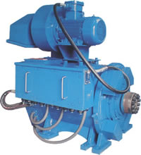
600v dc traction motor mud pump in stock

We supply a full line of AC and DC drilling motors for SCR and VFD electric drilling rigs. Our model SDM-800DC DC drilling motor is an identical match of GE752 traction motor.
It has the same footprint and is interchangeable with it. Our AC drilling motors are similar with GEB22 drilling motors but with more models and options. The typical application of our traction motors in drilling industry includes mud pumps, drawworks, and rotary tables.
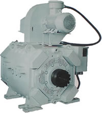
GE manufactures rugged electric drilling motors for the toughest applications in the oil and gas industry. The company has pioneered the electrification of the drilling rig and continues today to lead the way in manufacturing DC and AC drilling motors for land and offshore drilling rigs.
GE engineers, manufactures, and tests GE drilling motors to withstand the harshest requirements. They are used today driving drawworks, mud pumps, cement pumps, rotary tables, top drives, and anchor-handling winches on all types of drilling rigs, all over the world.
GE’s ongoing research and development efforts provide innovative and increasingly efficient technology continue to produce electric motors that are a more reliable and efficient power supply – especially in extreme weather conditions – and able to decrease noise on the rig, making a safer working environment. Combined with a potentially smaller “envelope,” this makes GE motors a better solution to meeting your rigs’ power supply requirements.
GE drilling motors are performing worldwide on all types of drill rigs, providing dependable operations of the rig’s primary equipment. GE drilling motors have been reported by rig operators to run for years without service or failure.
The company has a worldwide network of authorized service facilities such as, Gulf Electroquip in Houston, Texas, USA, for both its AC and DC drilling motors. These service facilities are audited and GE’s personnel have been trained to assure that they meet the quality standards required to repair GE’s drilling motors.
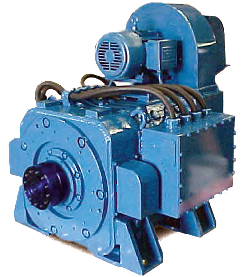
Cameron AC electric motors improve the performance of your mud pumps, drawworks, and rotary tables. Custom configuration is available, and ATEX, ABS, and DNV certification can be provided for new motors. Our flexible design offers you a choice between a tapered shaft or BullShaft to meet specific application requirements.
Cameron AC traction motors are designed and manufactured to handle deep drilling applications. Available in 400-hp, 550/600-hp, 1,150-hp, and 1,500/1,600-hp models, these inverter motors are designed specifically for 460-V to 690-V duty and deliver maximum efficiency. To meet varying installation requirements, our AC motors are available in vertical or horizontal designs.
Unlike conventional traction motors, Cameron AC motors have a unique design that meets the requirements of oil and gas applications. A key characteristic of the motor is the ability to provide a high level of torque at speeds ranging from 0 to 800 rpm (select motors can achieve a maximum speed up to 3,000 rpm). The torque generated at a wide range of speeds can enhance the performance of a broad array of drilling equipment driven by these motors.
MUD PUMPS:Two (2) Gardner Denver PZ-11"s (1600 hp each) With 7500 PSI Southwest fluid ends, powered by (4) AMD 800 hp DC Traction Motors. 5x6 Charge Pumps, Belts, Belt Guard.
All CategoriesAir compressors (2)Air compressor (1)Screw air (1)Attachments (2)Bucket (1)Screen (1)Backhoes (1)Excavators (1)Compactors (2)Compactor (1)Roller (1)Drill Rigs (1)Drilling (20)Brakes (1)Cat walk (1)Drilling Rig (1)Equipment (5)Mud Mixing Tank (3)Mud Pits (2)Pipe wrangler (1)Pumps (3)Solids separation (3)Electrical Equipment (4)Circuit Breaker (1)Cutler Hammer (1)Eaton (1)Switchgear (1)Engines (22)Cores (2)Diesel (5)Drilling (2)Drilling Rig (1)Engine (5)Equipment (2)Natural Gas (2)Oilfield (1)Pump drive (1)Pumps (1)Generators (13)Cat (2)Diesel (5)Generator (5)John Deere (1)Heaters (3)Air heater (1)Blower (1)Indirect fired heater (1)Iron (2)Pipe (1)Sucker Rod (1)Man Camps (3)Man Camp (2)Rig House (1)Mud Pumps (24)1000hp (4)Cat (1)Diesel (2)Emsco (3)Engine (1)Mud pump (7)Pump (6)Natural Gas Compression (10)Compressor Station (3)Engine (1)Frick (2)Natural Gas (3)Waukesha (1)Oil Field (4)Bathroom (1)Shipping container (1)Support Equipment (1)Tanks (1)Production (3)Injection (1)Pump (1)Pumping Unit (1)Road Graders (3)Blade (1)Road Grader (1)Service Trucks (1)Service Truck (1)Silos (2)Sand silos (1)Tanks (1)Support Equipment (17)Accumulator (4)Closing Unit (3)Drilling Rig (2)HPU (1)Koomey (3)Mud pump (1)Oilfield (1)Power Swivel (1)Tanks (1)Trailer (4)Flatbed (1)Gooseneck (1)Step deck (1)Trailer (1)Trucks (1)Water Truck (1)Valves (82)

E1700 Drawworks Ideco, with Two (2) 752 Type series wound DC traction motors with 7040 Baylor Auxiliary Elmagco Eddy Current brake. Rotary Skid (Drawworks Driven Rotary)
Mud Pumps Three (3) Continental Emsco 1600 HP packages each with master skid, two (2) 752 series wound DC traction motors, drive sheaves, belts, belt guards, charge pump and liner wash system as seen in pics.
Mud System 2500 BBL., mud system complete with agitators, centrifugal pumps, Three (3) Swaco 4 Panel Shakers, Desander, Desilter, Vacuum Degasser and mixing hoppers. Tanks & Houses Two (2) Water Tanks (1x Round, 1x Square Crimp) One (1) Trip Tank One (1) Diesel Fuel Tank One (1) Parts/Change House One (1) Doghouse
Miscellaneous Gardner Denver 500T Block w/Mast Raising Beckett 27.5” Ideco K Rotary Table, Mud/Gas Separator, Koomey BOP Closing Unit, Drill line spooler, Two (2) Air hoisting winches. Two (2) Junk Bin Skids w/ Misc Handling Tools, etc.

Finally, keep in mind that the VSD is part of an overall system, comprised of an incoming power source, the drive itself, a downstream load (motor), panel- or field-mounted controls, and all of the conductors and protective devices interconnecting them. A VSD fault might very well indicate that the drive itself is functioning perfectly by identifying a problem with the power supply or the motor it is controlling.
The motor load is too heavy for the drive: Drives are correctly rated based on the amperage they can carry without exceeding their temperature rating. The drive’s rated amperage must meet or exceed the motor’s full load amperage (FLA) as indicated on the motor nameplate, AND the drive’s overload capacity must be able to support the motor’s starting current under normal operating conditions. Because starting current can vary based on the load the motor is driving, most manufacturers list two amperages for a given drive – normal duty (a.k.a. standard duty or, in some cases, light duty) and heavy duty. These duty ratings are intended to reflect the torque required to support the connected loads – normal duty ratings apply to variable torque (also called quadratic) loads such as centrifugal pumps and fans, while heavy duty ratings apply to constant torque or constant horsepower loads such as compressors, positive displacement pumps, presses, drill presses, etc. An example of the difference between these two ratings for several 480V drives from the Yaskawa GA800 series is shown in Fig. 1. Note that the ratings for heavy duty are significantly lower, which simply indicates that when a drive is used for a heavy duty application it will, on average, see more current draw during load changes (startup, rapid accel/decel, etc.) and so will need more headroom to accommodate this.
If it’s confirmed that the drive is sized properly but overcurrent issues remain, other causes should be explored. Measuring the motor’s current draw with a true RMS ammeter is a good first step. This can indicate if the motor needs further examination. Excess current draw can result from motor insulation breakdown (see below), internal short-circuiting, or excessive bearing wear.
The motor insulation is breaking down:This can result from age, prolonged control by a VSD, overheating, and other factors. An insulation resistance test is used to determine the quality of the motor’s insulation. A full explanation of this type of testing is beyond the scope of this article, but in general, spot reading tests can be valuable if the motor’s insulation resistance history is available, and time vs. resistance testing is better if no history of motor insulation resistance has been recorded. (See Fig. 2 for an example of time vs. resistance test results.) The key here is to have this testing done by qualified personnel; there are many variables which can influence the testing and reduce its accuracy and so must be taken into consideration.
Insulation breakdown is usually corrected by rewinding or replacing the motor. It is helpful to know why the breakdown occurred in the first place to see to it that the same cause(s) don’t reduce the “new” motor’s life as well. One such cause is due to the inherent design of insulation systems in older motors. Many older motors are not able to effectively withstand the voltage spikes seen at the motor terminals when controlled by a VSD for prolonged periods. These spikes result from the VSD’s rapid output pulses used to create the synthesized AC waveform sent to the motor. They are inherent to most modern drives and can only be reduced by using output filters. Just how much they increase voltage levels at the motor terminals is determined by the capacitance of the drive, motor leads, and motor; the length of the motor leads; the drive’s pulse rise time and switching frequency; and the presence or absence of the aforementioned output filters. Suffice to say that it is not uncommon to see voltage levels of 2 – 4 times the line (input) voltage level at the motor terminals when a VFD is used. This is why motors suitable for being controlled by a VFD are typically built to standards such as North America’s NEMA MG 1 Parts 30 & 31, which requires motor insulation systems to be built to withstand at least 3.1x the motor rated voltage (for ≤600V motors) or 2.04x the motor rated voltage (for >600V motors). In practice, it is not uncommon to see manufacturers such as GE build 460V motors with 1800V (or higher) insulation systems. Such systems were generally not available in older motors, so even those with relatively intact insulation systems may not be able to withstand drive-induced voltages for long periods.
Motor overheating is another major cause of VFD overcurrent faults. This can be the result of the over-voltage effects mentioned above, which can gradually heat up terminal end windings. It can also be the result of operating the motor in high ambient environments. Additionally, operating a self-cooled motor (e.g. a totally enclosed fan-cooled design) at low speeds continuously can cause the motor to heat up due to reduction of air across the cooling fins. This is why it is recommended to not run fan-cooled motors at less than about 60% of rated speed for extended periods, even though a drive certainly allows this. It is widely recognized that for every 10 degrees C increase in winding temperature above the motor rated ambient, motor life is reduced by 50%. While there are a lot of factors affecting the accuracy of this statement, it remains true that motor life is reduced by overheating. So what to do about motor overheating? Taking care of the easiest things first, determine the range of operating temperatures the motor is exposed to, and see what can be done to reduce the excessive ones. Then, if you find that your self-cooled motor is running too slowly, see whether your process can handle an increase in motor speed (or replace the motor with one with a lower rated speed, if that’s economically feasible). Separate blower systems for motor cooling can also be installed (see Fig. 3), and gear reduction may be another option depending on cost and space constraints. Finally, if you’ve addressed all of these issues and find the problem remains, make sure you test the motor thoroughly to determine if a rewind or replacement is needed.
– Courtesy General ElectricMotor lead insulation is breaking down:The impact of this may be obvious – a phase-to-phase or phase-to-ground short circuit that trips the drive and, perhaps, upstream protective devices. In the process, the drive’s output section may be permanently damaged, depending on the timing and location of the short. The VFD will see weakening insulation as an increase in current leakage, placing additional stress on the drive output. Overcurrent faults can be the result. In some cases, particularly where proper grounding and shielding methods are not followed, the leakage current can also affect nearby wiring and/or components through capacitive coupling (See Fig. 4). Cable insulation testing is a good, but often ignored, tool in a solid preventive maintenance plan. Done correctly, it will reveal impending problems without damage to the cable or unpredictable downtime. In any case, replacing the cable is the only option.
Dynamic braking for rapid deceleration is too aggressive: Large, high-inertia loads such as chippers, grinders, centrifuges, and even some large diameter fans can take several minutes to completely coast to a stop if not actively braked. Drives typically use current injection – sometimes referred to as dynamic braking or flux braking – or stepped frequency changes to decrease motor stopping time. An illustration of dynamic braking for the Yaskawa A1000 drive is shown in Fig. 5. If the parameters that govern the chosen braking method aren’t set correctly, overcurrent faults can occur. A lot of this is trial and error; loads can change depending on the application, and it may take some experimenting to determine the best settings to use under the range of normal operating conditions.
– Courtesy Yaskawa America, Inc.The drive is issued a Run command while the motor is coasting, and Speed Search is not enabled: While the motor is coasting to a stop it retains considerable inertia. If a Run command is sent during coasting, the drive can experience an increase in current through the DC bus. Many drives have an internal setting to “catch a flying motor”; i.e. determine its speed and match it with the drive’s output. By carefully controlling the current, an overcurrent fault can be avoided. Activating this function is typically a matter of adjusting a few parameters, and it is dependent to some extent on the control method selected (V/f, open loop vector, or closed loop vector). Changing load conditions can also mean that some trial and error is needed to get the settings correct.


 8613371530291