
7500 psi mud pump nov free sample
Choose a used Emsco FB-1600 Triplex Mud Pump from our inventory selection and save yourself some money on your next shallow drilling oilfield project. This Emsco FB-1600 Triplex Mud Pump is used and may show some minor wear.
We offer wholesale pricing on new Emsco FB-1600 Triplex Mud Pump and pass the savings on to you. Contact us to compare prices of different brands of Mud Pump. This equipment is brand new and has never been used.
Our large network often has surplus Emsco FB-1600 Triplex Mud Pump that go unused from a surplus purchase or a project that was not completed. Contact us to see what Emsco FB-1600 Triplex Mud Pump we have in inventory. The surplus Emsco FB-1600 Triplex Mud Pump are considered new but may have some weathering depending on where it was stored. Surplus oilfield equipment is usually stored at a yard or warehouse.
We have refurbished Mud Pumpthat have been used and brought up to functional standards. It is considered a ready to use, working Mud Pump. Please contact us for more information about our refurbished Emsco FB-1600 Triplex Mud Pump. These Mud Pump have been used and brought up to functional standards. It is considered a working Mud Pump. Please contact us for more information about the product.

The NOV FC-1600 Triplex Mud Pump is made of rugged Fabriform construction and designed for optimum performance under extreme drilling conditions. It is compact and occupies less space, yet delivers unequaled performance. The pumps are backed by several decades of design and manufacturing experience, and are considered leaders in the field.
NOV FC-1600 Triplex Mud Pump is conservatively rated at relatively low rpm. This reduces the number of load reversals in heavily stressed components and increases the life of the fluid end parts through conservative speeds and valve operation.
The NOV FC-1600 Triplex Mud Pump design provides an inherently balanced assembly. No additional counterbalancing is required for smooth operation. No inertia forces are transmitted to the pumps’ mountings.
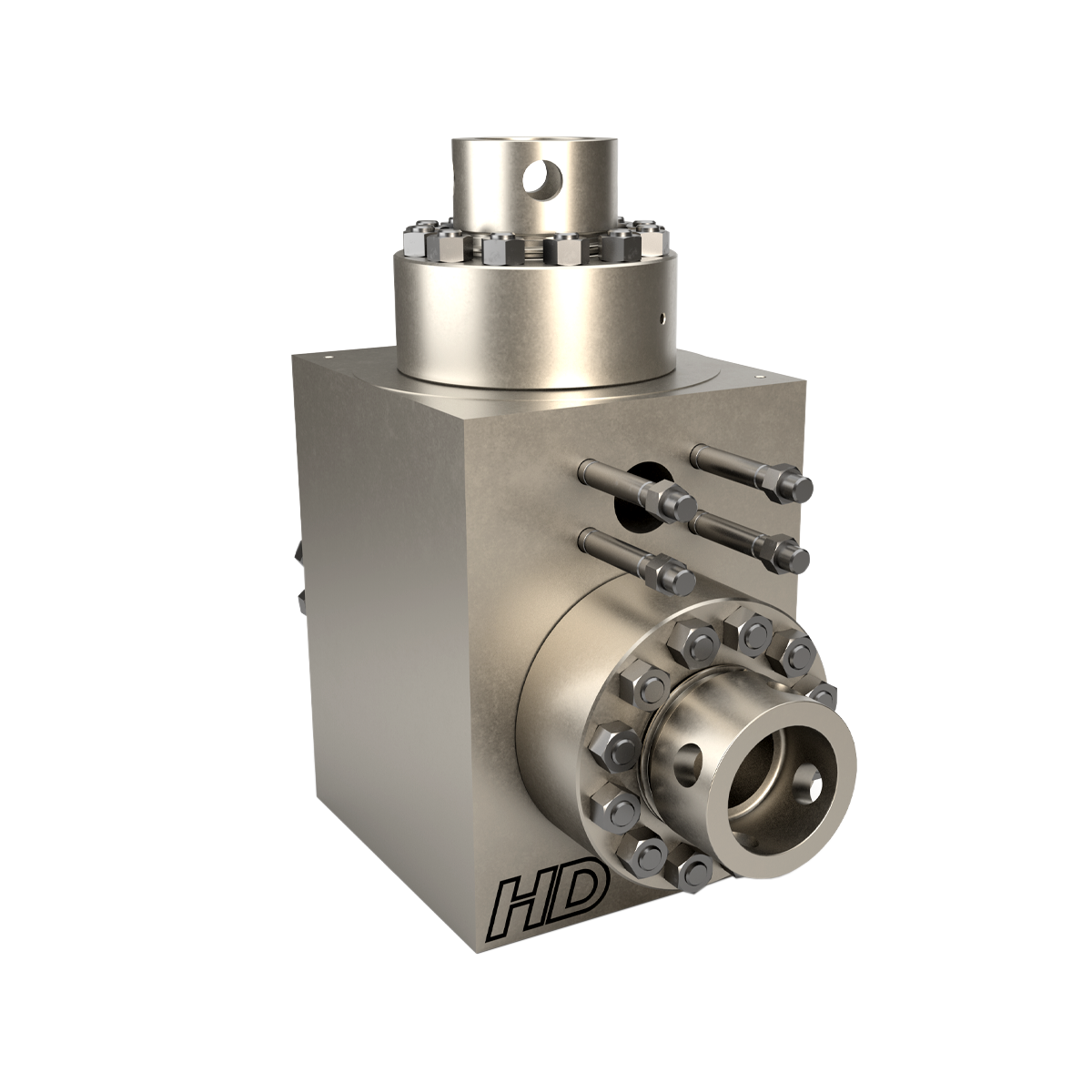
A Triplex Mud Pump sometimes referred to as a drilling mud pump or mud drilling pump. NOV FC-1600 Triplex Mud Pump is a reciprocating piston/plunger pump designed to circulate drilling fluid under high pressure (up to 7,500 psi) down the drill string and back up the annulus. A mud pump is an important part of the equipment used for oil well drilling.

The 2,200-hp mud pump for offshore applications is a single-acting reciprocating triplex mud pump designed for high fluid flow rates, even at low operating speeds, and with a long stroke design. These features reduce the number of load reversals in critical components and increase the life of fluid end parts.
The pump’s critical components are strategically placed to make maintenance and inspection far easier and safer. The two-piece, quick-release piston rod lets you remove the piston without disturbing the liner, minimizing downtime when you’re replacing fluid parts.

Mud-Pump Gear Sets . . . . . . . . . . . . . . . . . . . . . . . . . . . . . . . . . . . . . . . . . . . . . . . . . . . . . . . . . . . . . . . . . 13
The ‘GlobalMud Pumps Market Price, Size, Share, Trends, Growth, Report and Forecast 2023-2028’ by Expert Market Research gives an extensive outlook of the global mud pumps market, assessing the market on the basis of its segments like type, operation, application, and major regions.
The need for mud pumps has increased along with the growing demand for minerals, oil, and gas. The market for mud pumps is anticipated to grow throughout the forecast period due to increased offshore mining activities and the globally expanding population. With the advantages it offers, the mud pumps market is expected to grow quickly. The market would be further boosted by rising demand for directional and horizontal drilling as well as the mud pump’s capacity to handle high-pressure drilling activities.
Due to technological advancements, mud pumps operate more efficiently and without producing harmful carbon emissions. Electric mud pumps are in higher demand, which may create new prospects for market expansion. The performance of mud pumps is influenced by the pump design along with a variety of other elements like pipelines, panel boards, and electricity. For maximum efficiency, manufacturers are therefore concentrating on improvements to the overall pumping system, which is aiding the mud pumps market.
Mud pumps are attracting attention as an innovative component of offshore drilling equipment as every hour, mud pumps help reach deeper levels, saving the rig operator time and money. In on-shore drilling, for instance, 7500-psi mud pump systems are becoming common.
Mud pumps are a particular kind of piston/plunger-driven pump that can use drilling fluids while under high pressure. Mud pumps are typically used in conjunction with other pumps and are a crucial component of heavy drilling techniques. These pumps assist in returning the drilling fluid to the surface after it has passed past the drill bit.
Triplex pumps are likely to hold a significant mud pumps market share since triplex pumps are lighter and more efficient than duplex pumps. Triplex mud pumps are widely used to circulate high-pressure drilling fluid for deep oil well drilling applications. They are more advantageous for use, especially in onshore and offshore oil well drilling applications, due to these applications.
The electrically powered mud pump market is expanding quickly due to its environmental advantages over fuel engine pumps. The mud pumps market value is anticipated to increase as a result of the increased exploration operations being carried out in all regions of the world to satisfy the growing demand for energy and minerals. In nations including the United States, Canada, China, and Argentina, shale gas exploration has expanded, which will raise the demand for oil rigs and consequently mud pumps.
The use of oil rigs, equipment, and mud pumps is being accelerated by operators in nations like the United States who are also relocating to isolated areas in Alaska. Old pumps are now being replaced by many governments, and oil and gas production businesses in Europe and the United States have noticed a continuous growth in this trend, thus aiding the market growth of mud pumps.
www.nov.com Document Number: D2G1008930-FDD-001 Revision: 01 Page: ii
www.nov.com Document Number: D2G1008930-FDD-001 TOCTABLE OF CONTENTS Revision: 01 Page: 1
www.nov.com Document Number: D2G1008930-FDD-001 TOC 1TABLE OF CONTENTS Revision: 01 Page: 1
www.nov.com Document Number: D2G1008930-FDD-001 TOC 2TABLE OF CONTENTS Revision: 01 Page: 1
www.nov.com Document Number: D2G1008930-FDD-001 TOC 2.1TABLE OF CONTENTS Revision: 01 Page: 1
Technical Specification Pre-Shipment And Storage PS-4030 02 Preservation For New-Build NOV Triplex Mud Pumps
Product Information Bulletin Triplex Mud Pumps Power 01-05-01-MP 06 End Lubrication Oil Additive and wear-in Period
RIG/PLANT REFERENCE REFERENCE DESCRIPTION Triplex Mud PumpADDITIONAL CODE SDRL CODE TOTAL PGS This document contains proprietary and confidential information National Oilwell Varco which belongs to National-Oilwell Varco, L.P., its affiliates orREMARKS subsidiaries (all collectively referred to hereinafter as "NOV"). It is loaned for limited purposes only and remains the property of NOV. 11000 Corporate Centre Drive Reproduction, in whole or in part, or use of this design or Suite 200MAIN TAG NUMBER DISCIPLINE distribution of this information to others is not permitted without the Houston, Texas 77041 express written consent of NOV. This document is to be returned to NOV upon request and in any event upon completion of the use for U.S.A.CLIENT PO NUMBER which it was loaned. This document and the information contained and represented herein is the copyrighted property of NOV. Phone: +1-281-854-0400 National Oilwell Varco Fax: +1-281-854-0607CLIENT DOCUMENT NUMBER DOCUMENT NUMBER REV
www.nov.com Document number PS-4030 Revision 02 Page 2
Revision Change Description 0 Initial Release 1 Updated Entire Document 02 Added NOV Standard Front Cover & Updated Page Formats
www.nov.com Document number PS-4030 Revision 02 Page 3
www.nov.com Document number PS-4030 Revision 02 Page 4
This specification covers the preservation and storage procedure for shipment of new-build NOV Triplex Mud Pumps shipped from the manufacturing plant.
This specification is intended to provide preservation of new-build NOV Triplex Mud Pumps for six (6) months from the shipment of the mud pump from the manufacturing facility. If a pump is to be stored for a period of time exceeding six (6) months, additional precautions should be taken as outlined in this specification.
National Oilwell Varco recommends that all pumps are inspected for any signs of corrosion and for proper preservation at a minimum every three (3) months for pumps stored outside and every six (6) months for pumps stored indoors.
Drain all water and clean out liner wash tank. Remove drain plug in bottom of liner wash pump and drain water then reinstall plug. Remove discharge flange from liner wash pump and pour one (1) pint of inhibiting oil-based concentrate (Cortec VpCI 329 Vapor Corrosion Inhibiting oil-based concentrate or equivalent) into liner wash pump. Rotate two (2) revolutions by hand to distribute the product. Re-install discharge flange.
Drain all oil from pump power end sump and remove crosshead covers and inspection covers. Clean out oil sump as per National Oilwell PS-3081 (Mud Pump Cleanliness). Spray all internal machined parts of power end and crosshead area with inhibiting oil-based concentrate (Cortec VpCI 329 Vapor Corrosion Inhibiting oil-based concentrate or equivalent). Rotate pump turn and re-spray. Pour quantity of inhibiting oil-based concentrate specified in the table below into power end sump.
Mud Pump Models Quantity of Inhibitor 14P, FC 2200 5 Gallons 12P, 10P, HD or A1700/1400PT, FB/FC/FD 1600, FB 1300 3 Gallons 9P, 8P, B or A850-1100PT, F/FD 1000, F 800 2 Gallons 7P, A600PT, FD 500 1 Gallon
For pumps equipped with chain drives, spray internal machined parts inside chain cases with inhibiting oil-based concentrate (Cortec VpCI 329 Vapor Corrosion Inhibiting oil based concentrate or equivalent).
www.nov.com Document number PS-4030 Revision 02 Page 5
Remove breather and pack with loose parts for later shipment with pump. Seal breather hole with a greased solid plug. Affix a warning label near the breather opening (see Exhibit 1).
Spray all machined unpainted loose parts and expendables to be shipped with pump with rust preventative (CRC SP400 or equivalent). All parts will be wrapped or boxed to prevent damage.
Affix one (1) warning label (see Exhibit 2) to the power end pump cover and one (1) warning label on the fluid end assembly of the pump. Affix warning labels on each loose part container. In cases where the equipment will be boxed at an offsite export packer, a sufficient number of warning labels will be supplied with the shipment.
www.nov.com Document number PS-4030 Revision 02 Page 6
Indoor storage is preferred whenever possible; but if outside storage is required, ensure pump is stored away from salt water spray, sand blast or other adverse conditions. It is highly recommended that ship loose parts be stored indoors to eliminate conditions that promote condensation and direct sources of moisture.
Note: It is recommended that inspections be carried out on six (6) month cycles when pumps are in indoors and three (3) month cycles when stored outside.
www.nov.com Document number PS-4030 Revision 02 Page 7
Any pump that has been in storage will need a thorough inspection prior to start-up to insure it has not been damaged in any way and that all parts are properly in place. Failure to observe the following points can result in serious damage. Before servicing the pump, the power end sump and chain drives housings will need to be drained of any inhibiting additive. The Cortec brand products used for preservation are compatible with all lubricating oils and need not be totally removed when putting equipment into service.
Product Name Company Contact Number Cortec VpCI 329 Gulf Corrosion Control (713)681-7500 CRC Industries Inc. SP400 Fastenal (713)983-7715 KOPR-KOTE Drago Supply Co. (800)553-2363
www.nov.com Document number PS-4030 Revision 02 Page 8
www.nov.com Document number PS-4030 Revision 02 Page 9
www.nov.com DOCUMENT OR DRAWING NO. PAGE 1 of ENGINEERING EDN-1688 12SUBJECT COMMISSIONING PROCEDURE, FB/FD-1600 APPROVED REVISED DATE REV.
TRIPLEX MUD PUMP GDH 02PREPARED BY DATE CHECKED BY DATE
DOCUMENT TITLE: Commissioning Procedure, FB/FD-1600 Triplex Mud Pump DOCUMENT OR DRAWING NO. PAGE 2 of ENGINEERING EDN-1688 12SUBJECT COMMISSIONING PROCEDURE, FB/FD-1600 APPROVED REVISED DATE REV.
TRIPLEX MUD PUMP GDH 02PREPARED BY DATE CHECKED BY DATE
1. Power End.................................................................................................. 3 2. Main Electric Drive Motors 3 3. Auxiliary A/C Motors. 4 4. Instrumentation........................................................................................... 4 5. Liner Wash System..................................................................................... 4 6. Fluid End.................................................................................................... 4 7. Suction Dampener/Desurger....................................................................... 4 8. Pulsation Dampener.................................................................................... 4 9. Pressure Gauge............................................................................................ 5 10. Reset Relief Valve....................................................................................... 5 11. Discharge Strainer 5 12. Mud Pump Drive Assembly. 5 a. Belt Drive Units 5 b. Chain Drive Units. 5
TRIPLEX MUD PUMP GDH 02PREPARED BY DATE CHECKED BY DATE
The initial startup procedures are written to assist the operator in preparing the pump packages for normaloperation. The startup procedures are separated into two categories: Part I: Pre-Commissioning, and PartII: Commissioning Procedures. It is suggested that a copy of these pages be made for each pump to beused as a check-off sheet.
Note: The rust preventative on the internal surfaces of the pump is oil-soluble and is compatible with the lubricants recommended above. It is not necessary to flush and drain unless the preservative has become contaminated (water, sand etc.).
TRIPLEX MUD PUMP GDH 02PREPARED BY DATE CHECKED BY DATE
Clean liner wash tank, if needed, and fill with fresh clean water. Ensure that supply hoses and spray nipples are installed correctly. Start pump and adjust regulating valve to maximum flow without splash onto the extension rods.
NOTE: When charging the bladder, make sure that the mud pump suction line valve has been closed and that all pressure has been bled off of the suction manifold surrounding the suction desurger
If a dampener is used, charge dampener with a hand-operated air pump to 10 PSI (0.7 bar). Once pump operations have been started, check the operation of the suction dampener by inspecting the sight glass. Add or release air pressure through the Shraeder valve to keep the diaphragm between the midpoint and the bottom of the sight glass.
TRIPLEX MUD PUMP GDH 02PREPARED BY DATE CHECKED BY DATE
Check the installation and the setting. NO SHUT-OFF VALVE is to be between the pump discharge and the relief valve. Ensure that piping from the discharge port goes directly to the mud tank/pit and is securely tied down, with a minimum downward slope of 1/4 per foot. Ensure that piping has pressure rating equal to the relief valve highest setting.
Check the chain guards to ensure that the chains will not drag on the guard. Check the oil pump to ensure that the relief valve is installed on the suction side. Start the pump and ensure that the spray nozzles are spraying oil over the full width of the chain. Adjust the relief valve to 15-25 PSI output with the warm oil. DOCUMENT OR DRAWING NO. PAGE 6 of ENGINEERING EDN-1688 12SUBJECT COMMISSIONING PROCEDURE, FB/FD-1600 APPROVED REVISED DATE REV.
TRIPLEX MUD PUMP GDH 02PREPARED BY DATE CHECKED BY DATE
Operation of the pump in parallel to check the SCR-Motor assignments and controls, volumetric displacement and mudline systems are at the option of the purchaser.
Check the discharge mudline to assure that all necessary valves are open. Ensure that the mud tanks are full of test fluid (mud/water) prior to startup.
Make the desired assignment of the SCR-Motor Control System to the pump motors, and open the throttle slightly. Check to ensure that charge pump and liner wash motors have started.
If no immediate problems are encountered, slowly throttle the pump to approximately 60 SPM and continue operating the mud pump while making the following inspections to assure that all systems are working properly:
Check oil pressure: Max. = 60 PSI (4.14 bar) cold oil. Min. = 5 PSI (0.344 bar) at any speed. Normal = 7-40 PSI (0.483-2.76 bar)
TRIPLEX MUD PUMP GDH 02PREPARED BY DATE CHECKED BY DATE
Pump A/C motor operating properly. Valves open for the proper volume of drilling fluid. Gauges/controls functioning properly.
Check the valve for proper relief setting. The valve should be set 10% above the pressure rating for the liner size being used. Refer to the nameplates on each side of the pump or the pump datasheet to obtain the operating pressure for that particular size liner. DOCUMENT OR DRAWING NO. PAGE 8 of ENGINEERING EDN-1688 12SUBJECT COMMISSIONING PROCEDURE, FB/FD-1600 APPROVED REVISED DATE REV.
TRIPLEX MUD PUMP GDH 02PREPARED BY DATE CHECKED BY DATE
The following are basic guidelines for conducting of an eight (8) hour operational test. The pump was test run under pressure in the manufacturing plant but with different motors and drives.
TRIPLEX MUD PUMP GDH 02PREPARED BY DATE CHECKED BY DATE
The overall performance of the unitized pump package should be continuously monitored during the eight hour test program. The following checks should be made and recorded each two hours of operation.
TRIPLEX MUD PUMP GDH 02PREPARED BY DATE CHECKED BY DATE
TRIPLEX MUD PUMP GDH 02PREPARED BY DATE CHECKED BY DATE
TRIPLEX MUD PUMP GDH 02PREPARED BY DATE CHECKED BY DATE
Triplex Mud Pump For Models: FD-500, FD-800, FD-1000 & FD-1600
RIG/PLANT REFERENCE REFERENCE DESCRIPTION Triplex Mud PumpADDITIONAL CODE SDRL CODE TOTAL PGS This document contains proprietary and confidential information National Oilwell VarcoREMARKS which belongs to National Oilwell Varco; it is loaned for limited 1530 W Sam Houston Pkwy. N purposes only and remains the property of National Oilwell Varco. Reproduction, in whole or in part; or use of this design or Houston, TX 77043MAIN TAG NUMBER DISCIPLINE distribution of this information to others is not permitted without the Phone 713-935-8000 express written consent of National Oilwell Varco. This document is Fax 713-935-8382 to be returned to National Oilwell Varco upon request and in anyCLIENT PO NUMBER event upon completion of the use for which it was loaned. National Oilwell VarcoCLIENT DOCUMENT NUMBER DOCUMENT NUMBER REV
www.nov.com Document number EPL- 1911 Revision 01 Page 2
www.nov.com Document number EPL- 1911 Revision 01 Page 3
www.nov.com Document number EPL- 1911 Revision 01 Page 4
www.nov.com Document number EPL- 1911 Revision 01 Page 5
PREFACE.................................................................................................................................... 31 INSTALLATION OF NEW PUMP ................................................................................... 112 SETTING THE PUMP ..................................................................................................... 11 2.1 Land Installations.................................................................................................. 113 SUCTION SYSTEM REQUIREMENTS........................................................................... 16 3.1 Caution ................................................................................................................. 164 PREPARATION OF POWER END ................................................................................. 17 4.1 Power End Lubrication.......................................................................................... 17 4.2 Installation of Crosshead Extension Rods and Diaphragm Stuffing Box Seals..... 185 PISTON AND LINER COOLING SYSTEM ..................................................................... 19 5.1 Stationary spray (View A, Fig. 6) .......................................................................... 20 5.2 Moving Nozzle ...................................................................................................... 206 ASSEMBLY OF FLUID END PARTS ............................................................................. 23 6.1 Valves and Seats.................................................................................................. 237 FD-500, FD-800 & FD-1000............................................................................................ 24 7.1 Liners.................................................................................................................... 25 7.2 Piston Rod ............................................................................................................ 25 7.3 Piston Rod Clamps ............................................................................................... 25 7.4 Liner Cage and Lower Valve Guide ...................................................................... 26 7.5 Cylinder head ....................................................................................................... 26 7.6 Discharge Valve Pot Covers ................................................................................. 268 FD-1600 .......................................................................................................................... 27 8.1 Liner...................................................................................................................... 28 8.2 Piston Rod ............................................................................................................ 28 8.3 Piston Rod Clamps ............................................................................................... 29 8.4 Lower Valve Guide and Cylinder Head................................................................. 29 8.5 Discharge Valve Pot Covers ................................................................................. 29 8.6 Discharge Manifold all models .............................................................................. 30
www.nov.com Document number EPL- 1911 Revision 01 Page 6
www.nov.com Document number EPL- 1911 Revision 01 Page 8
www.nov.com Document number EPL- 1911 Revision 01 Page 9
www.nov.com Document number EPL- 1911 Revision 01 Page 10
www.nov.com Document number EPL- 1911 Revision 01 Page 11
Your National Oilwell Varco pump has been completely assembled and test operated under pressure before being shipped to the field. Unless otherwise instructed, the lubrication is drained from the power end and the expendable parts are removed from the fluid end. Before putting the pump into service, the following precautions and operations must be performed or checked.
2 SETTING THE PUMP The skids under the National Oilwell Varco pumps are suitable for most any type of installation. It should be noted, however, that the box type construction of the power frame has high resistance to bending but relatively less resistance against twist. Therefore, the support under the pump must be level and adequate to support the weight and operating forces exerted by the pump.
2.1 Land Installations In land installations, a mat of 3 X 12 (76.20 mm x 304.8 mm) boards laid side crosswise to the pump skids for the entire length, or at a minimum, at the points indicated in Fig. 2, is usually sufficient. The boards should be a few feet wider than the width of the pump skid runners. Wet or marshy locations may require a more stable foundation.
www.nov.com Document number EPL- 1911 Revision 01 Page 12
Suitable means, such as National Oilwell Varco pump spacers as shown in Fig. 3, should be used to keep the pump anchored and the drive in alignment. National Oilwell Varco mud pump spacers provide 8-1/2 (215.9mm) adjustment. Any desired length may be obtained by lengthening the standard pipe spacer, which is made of 3 (76.20mm) extra strong pipe.
www.nov.com Document number EPL- 1911 Revision 01 Page 13
2.1.1 Permanent Installations On permanent installations such as barge, platform, structural base, or concrete slab, where pump skids are bolted down, it is essential that the skids be properly shimmed to prevent possibility of twisting or distorting the power frame. The pump skids must sit solid on all shim points with bolts loose.
On barge installations, the pump skids are generally bolted down to T-beams running parallel and in line with the pump skids. Install shims at points shown in Figs. 2 and 4 and observe caution of proper shimming to prevent twist or distortion.
On installations where the power unit or electric motor is mounted integrally with the pump skids, the preferred installation would be to set the pump package on the T-beam skids and provide retention blocks rather than bolts to hold it in place. This will allow the pump to float and minimize the transfer of barge deck or platform distortion into the frame.
2.1.2 Installation of the Drive The drive between the mud pumps and the power source, whether V-belts or multi-width chains, should be installed with the greatest care to assure maximum operating life with minimum of unexpected or undesirable shutdowns due to drive failures.
www.nov.com Document number EPL- 1911 Revision 01 Page 14
Adjust the belt tension by moving the sheaves apart until all of the sag has just been eliminated from the tight side of the belt and some of the belts on the slack side. Then increase the centers approximately (13mm) for each 100 (2540 mm) center distance. Example: On 150 (3810 mm) center, move pump an additional (19.5 mm).
www.nov.com Document number EPL- 1911 Revision 01 Page 15
DO NOT OBTAIN BELT TENSION BY PICKING UP END OF PUMP AND ALLOWING BELTS TO TIGHTEN UNDER WEIGHT OF PUMP AS END IS BEING LOWERED TO THE GROUND.
The pump drive chain lubrication system on the majority of National Oilwell Varco pumps is an independent system having its own oil pump, reservoir, and drive. Fill chain case to the indicated level with a non-detergent oil as follows:
- Daily check of oil level. - Daily check on condition of oil. - Frequent check on oil pressure. (5-15 psi) (.352 - 1.06 kg/cm) - Volume of oil being applied to chain. - Condition of nozzles in spray tube. - Condition of oil pump drive (V-belts or chain)
www.nov.com Document number EPL- 1911 Revision 01 Page 16
NOTE: Oil pressure may be adjusted with the pressure relief adjusting screw on the rear of the pump housing. Pressure drops may also indicate suction and discharge filter screens need cleaning.
3 SUCTION SYSTEM REQUIREMENTS Individual installation conditions will dictate the design of the suction system. The suction of the FD-series pumps must have a positive head (pressure) for satisfactory performance. The optimum suction manifold pressure is 20-30 psi (1.75-2 kg/cm) for maximum volumetric efficiency and expendable parts life. This head pressure is best supplied by a 5 x 6 centrifugal pump with 40 h.p. 1150 rpm electric motor. This type of drive requires a device to automatically start and stop the centrifugal pump motor simultaneously with the triplex pump. On DC electric powered rigs a signal can usually be supplied from the DC control panel to energize a magnetic starter when the mud pump clutch air line will provide a set of contacts for energizing the magnetic starter when clutch is engaged.
The charging pump can also be belt driven from the triplex pinion shaft charging type of drive is not as efficient at slow speeds with viscous fluids.
Under some conditions the FD-Series pumps may be operated without a charging pump, provided the fluid level in mud pits is higher than the top of the liners, fluid being pumped is low viscosity and suction line must be short, straight and of at least the same diameter as suction manifold inlet.
The suction lines should be piped with valve arrangements so the charging pump can be by-passed so operation can be continued in event of charging pump failure or for maintenance. Operation without a charging pump can be improved by replacing the suction valve springs with a weaker spring.
Suction desurgers are a very effective aid for complete filling of the liners and dampening pulsations in the suction line which results in a smoother flow in the discharge line. If your pump is equipped with a suction desurger it must be pre-charged with compressed air before operations are begun. See suction desurger manual for charging instructions.
3.1 Caution Do not pipe the return line from the shear relief valve back into the suction system as a relief valve operation will cause a sudden pressure rise in the system vastly greater than the system pressure ratings, resulting in damage to manifold, suction desurger and centrifugal pump.
www.nov.com Document number EPL- 1911 Revision 01 Page 17
4 PREPARATION OF POWER END Your National Oilwell Varco pump has been completely assembled and test operated before being shipped to the field. Unless otherwise instructed, the lubrication is drained from the power end, and the expendables are removed from the fluid end for storage protection. Before operating the pump, the following must be performed or checked:
Before installing lubricant, open inspection door in cover and check oil reservoir for possible accumulation of condensation, etc., and drain and flush by removing the pipe plugs on each side of the pump.
Add the proper type and quantity of lubrication in the power end. Refer to the Lubrication Section of this manual, or lubrication plate on pump frame for type and quantity required.
Recheck oil level after pump has operated for a period of 15 minutes. Shut pump down and allow approximately five minutes for the oil level to equalize. Check at oil level gauge, Item 1, Fig. 1. It is usually necessary for a few more gallons of oil to be added due to a certain amount being retained in the crosshead area and frame cavities.
www.nov.com Document number EPL- 1911 Revision 01 Page 18
With reference to Figure 5, remove the diaphragm stuffing box and plate (1) and rotate pump so that crosshead is at the front of the stroke. Thoroughly clean the front of the crosshead and the face of the crosshead extension rod. Insert alignment boss on crosshead extension rod into the crosshead bore and tighten the retainer bolts (2) to the following torque. Safety wire bolt heads.
www.nov.com Document number EPL- 1911 Revision 01 Page 19
www.nov.com Document number EPL- 1911 Revision 01 Page 20
Two types of piston and liner cooling systems have been used on National Oilwell Varco FD-Series Pumps -- the stationary spray type and a moving nozzle type. Ref. Fig. 6. The manifold (1) for supplying cooling fluid to the piston and liner assemblies is identical on both systems. Cooling fluid from either a remote source such as a water line, or from a pump and reservoir system unitized on the pump skids (Ref. Fig. 7) must be piped into the manifold at the connection located in the pump frame under the crosshead extension rod section.
www.nov.com Document number EPL- 1911 Revision 01 Page 21
www.nov.com Document number EPL- 1911 Revision 01 Page 22
With reference to Fig. 7, maintain electric motor (1) and centrifugal pump (2) according to manufacturers specifications. Rotation of the pump should be clockwise when viewed from the impeller end.
www.nov.com Document number EPL- 1911 Revision 01 Page 23
www.nov.com Document number EPL- 1911 Revision 01 Page 24
www.nov.com Document number EPL- 1911 Revision 01 Page 25
www.nov.com Document number EPL- 1911 Revision 01 Page 26
7.4 Liner Cage and Lower Valve Guide Install rear liner seal (5) and push into position against liner shoulder. Slide liner cage (6) into fluid end, align one hole in the cage with lower valve pot bore. Set lower valve guide (8) over valve stem through lower hole in cage with the wings on the guide turned crosswise to the pump. Press down on the guide, compressing the valve spring (7) until the guide can be rotated turn and seat into place underneath the cage. Insert the lower valve guide locking clip (9) through the pad eyes on the lower valve guide and rotate clip to the right to lock the valve guide tight against the OD of the liner cage. It may sometimes be necessary to put more or less bend in the center of the clip to make it retain the guide tightly while the clip handle snaps into position on the right hand side.
7.5 Cylinder head Insert the outer seal (5) in the fluid end bore against the liner cage. Slide the cylinder head plug (10) into fluid end. Apply a liberal coat of grease to both mating thread surfaces of the cylinder head (2). Screw cylinder head in and tighten with wrench furnished with pump and sledge hammer.
www.nov.com Document number EPL- 1911 Revision 01 Page 27
Note: All of the parts in this fluid end assembly are designed with metal to metal seating to alleviate friction wear from breathing action encountered in modern high pressure pump operation. For this reason it is essential that all parts be clean and free of rust, nicks and burrs before being assembled.
www.nov.com Document number EPL- 1911 Revision 01 Page 28
Note: FD pumps are factory equipped with jib booms and liner handling tools. If older pumps are converted to FD fluid ends a jib boom should be added to the pump frame as considerable weight is involved in handling the liner assembly.
www.nov.com Document number EPL- 1911 Revision 01 Page 29
www.nov.com Document number EPL- 1911 Revision 01 Page 30
8.7 Suction Flange The suction flange has a 12 (305mm) standard pipe thread connection and is custom made to match the companion flange on the pump suction manifold. The flange connection is sealed off by an O-ring seal (14 OD x 13-1/2 ID x ), (356mm OD x 343mm I.D. x 6.35mm Dia.)
8.8 Accessory Manifold Fig. 10 is not the standard discharge arrangement on the model FD-1600 pump, which uses the strainer cross configuration. An accessory manifold, Fig.10, is available for installation on the discharge manifold opposite the discharge end. The manifold will accommodate a discharge pulsation dampener (1) and provides two 3-6000 PSI*side outlet connections for such items as a pressure gauge (2) and a shear relief valve (3).
www.nov.com Document number EPL- 1911 Revision 01 Page 31
The shear relief valve (3) is installed on the discharge manifold for the purpose of protecting the pump from excessively high pressure overloads.
The relief valve must be installed so that it will be directly exposed to the mud. DO NOT PUT ANY TYPE OF SHUT OFF VALVE between the relief valve and the manifold. Pipe the discharge side of the relief valve directly into the mud pit with as few turns in the line as possible. IT IS NOT RECOMMENDED for the discharge side of the valve to be piped into the suction line of the pump.
Precharge dampener before starting up pump. Precharge pressure should not be more than 2/3 of the pump discharge pressure, or a maximum of 650 PSI. (46 kg/cm)
9 LUBRICATION Proper lubrication of the moving parts in any piece of machinery is the most important single factor affecting its ultimate life. To obtain maximum trouble-free service life from the power end of the National Oilwell Varco pump, it is necessary to perform routine maintenance care and inspections to insure the proper amount of CLEAN lubricant is being provided.
www.nov.com Document number EPL- 1911 Revision 01 Page 32
The FD-Series pumps utilize the controlled flow oil bath splash and pressure system to lubricate the entire power end. The type of pressure system provided in each individual pump will govern the minimum SPM at which the pump can be operated, i.e. pumps which have pressure lubrication only to the main and pinion bearings, have a minimum rated speed of 40 SPM. Pumps in which pressure lubrication is provided to the main, pinion, and crosshead bearings and crosshead compartments may be operated at a minimum speed of 25 SPM, provided there is a minimum of 5 PSI oil pressure. (352 grams/cm)
CAUTION: The pressure lubricating system can be provided with an externally mounted oil pump driven through V-belts or electric AC motor; or an internally mounted oil pump driven from the main gear. When an internally mounted oil pump is used, the direction of rotation of the pinion shaft must be as shown in Fig. 11.
www.nov.com Document number EPL- 1911 Revision 01 Page 33
9.2 Controlled Flow Splash System The controlled flow splash lubrication system is the same for all FD-Series pumps, regardless of the type of oil pump drive provided for the pressure system. In the controlled flow splash system, the main gear picks oil up from the reservoir, and when the teeth mesh with the pinion, the oil is displaced into various troughs and compartments in the frame. With reference to Figure 13, the oil thrown into trough (7) is directed through the oil tube (8) to the two pinion bearings.
www.nov.com Document number EPL- 1911 Revision 01 Page 34
9.3 Total Pressure lubrication System The total pressure lubrication system, incorporating the internally mounted oil pump for the FD-series pumps, is shown in Figure 13.
In this system, filtered oil is supplied to the pump through the suction filter (1) and is discharged from the pump into the manifold block (2). Oil is distributed from the manifold block to the pinion shaft bearing oil line (3) and spray nozzle (3A); and to the main bearing oil line (4) and the crosshead compartment manifold block (4A) located above the crosshead compartment. The crosshead compartment manifold block (4A) distributes oil to the crosshead, crosshead bearings, and extension rods. Pumps which do not have the crosshead compartment manifold block (4A) do not have the total pressure lubrication system, and therefore have a minimum rated speed of 40 SPM.
www.nov.com Document number EPL- 1911 Revision 01 Page 35
A pressure gauge (5) is mounted on the back wall of the frame to show oil pressure being maintained in the manifold block. The oil pressure will, of course, vary with the speed of the main pump, however if a sudden pressure drop or increase occurs, refer to the section on maintenance of lubrication system for possible cause.
A pressure relief valve (6) is mounted to the manifold block to keep excess pressure form damaging oil pump and drive. The relief valve is preset at 40 PSI and must not be tampered with.
NOTE: If specified, the oil pump for the pressure lubrication system can be independently powered by an electric motor or some other type of prime mover. When the independently driven oil pump is used, some type of alarm device or power interlock must be installed to assure the oil pump is operating when the main pump is put into service.
When installing the internally mounted oil pump (9, Fig. 13), position pump so that the back face of the drive gear is flush and parallel with the edge of the main gear, and gear teeth have*.010-.015 backlash. Remove inspection plate on power end cover for access to the internally mounted oil pump and filter screen. (* .25 - .38mm)
www.nov.com Document number EPL- 1911 Revision 01 Page 36
A typical layout for the pinion shaft driven oil pump is shown in Fig. 14. The oil pump (1) is piped into the oil system through the suction and pressure connections on the bottom inside wall of the power frame. Ref. Item 10, Fig. 13. The V-belt drive (2) is adjusted by moving pump up or down on the mounting bracket.
Adjust the V-belt drive (2) to a point where the two halves of the belt can almost be pinched together between the thumb and fingers at the center of the drive. Overtightening can cause premature failure of the pump.
10 MAINTENANCE OF THE LUBRICATION SYSTEM Adequate lubrication of the moving parts is, as stated, the most important single factor affecting the ultimate service life of the pump. CARE AND MAINTENANCE of the system is the sole responsibility of the operator or crew to which it has been assigned, and the extent to which this is applied will determine the amount of trouble-free service life that will be obtained.
The lubricant recommendations shown below, on the name plate on the side of the pump, or in the General Lubrication Bulletin included with this manual, are the result of extensive field tests. Substitutions should be made only in extreme emergencies.
www.nov.com Document number EPL- 1911 Revision 01 Page 37
ONCE EACH TOUR, check and maintain oil level at the FULL mark on the bayonet gauge. PUMP MUST BE SHUT DOWN and allowed to stand idle for approximately five minutes to allow oil level to equalize.
ONCE EACH SIX MONTHS, or more often if oil becomes contaminated with abrasive particles or corrosive compounds, drain and flush the oil reservoir and refill with new lubricant. Oil drains are located on either side of the pump frame.
Routine inspection on condition of oil should be made as condensation of moisture in the air, intrusion of mud, water or dirt, can necessitate a more frequent oil change.
A settling chamber is located in the forward area of the power end floor. Contamination in the oil splashed into this area is allowed to settle out and should be drained out of the pump through the clean out covers located on the frame wall underneath the crosshead inspection doors.
Once each month, remove clean out covers on both sides of pump to drain contaminated oil from settling chamber. Approximately 15-gallons of oil will be lost; replenish the main reservoir to compensate for the amount drained out.
- Clogged suction screen - Low oil level - Slipping V-belt drive - Broken or loose connections - Damaged or worn oil pump - Defective Relief Valve
www.nov.com Document number EPL- 1911 Revision 01 Page 38
Inspect the condition of the main gear teeth and pinion gear teeth for any indications of abnormal wear. During the initial break-in period there will be some pitting on the face of the gear teeth. This is referred to as initial pitting and is not harmful to the life of the gear. However, if routine inspection indicates the degree of pitting continues to increase, immediately contact the local representative of the pump manufacturer for a more thorough inspection of the gear.
www.nov.com Document number EPL- 1911 Revision 01 Page 39
11.2 Roller Bearings Although the basic construction of the various sizes of National Oilwell Varco pumps varies somewhat, they all have one very important detail in common -- roller bearings. A roller bearing is a precisely built machine within itself; therefore, careful handling is required in order to obtain the long service life and high load carrying characteristics associated with anti-friction bearings.
www.nov.com Document number EPL- 1911 Revision 01 Page 40
www.nov.com Document number EPL- 1911 Revision 01 Page


 8613371530291