
air lift mud pump factory

The pumps PM are made of corrosion-proof materials conforming to conditions for conveying potable water (GENOVA system). During air flow cut-off the pump’s construction provides separation of the supply system from the media pumping zone by means of a diaphgram perforated valve, closed by hydrostatic pressure.
The pumps are highly reliable and easy to assemble owing to the use of PVC hose as an intake end. The hose can be formed depending on the shape of the tank.
The capasities of the pumps (specyfied in laboratory conditions for clean water and constant depth Hz=1,5 m) are presented in the diagram showing the dependance of air demand supplied to the pump on the lifting height “H” of the medium being pumped (see data sent by fax).
The capasity of PM 110, at immersion depth Hz= 4m, is 15-20m3 (at H=0,5 m). The pumps can operate in a complex system allowing for multiplication of capasity. The lenghts of ends, intake L2 and exhaust L1, and air supply hose are specyfied by the buyer. We suggest the purchase of the very “heart” for individual assembly.

Distributor of engineered fluid handling pumps, packaged pumping systems, repairs, parts, & integrated pump control systems. Mud pumps, chiller/condenser pumps, plumbing pumps, boiler feed systems, in-line circulators, condensate systems, sump & sewage pumps, end suction pumps, submersible sump & sewage, non-clogs & grinders, self primers, packaged lift stations, variable speed pump systems, metering pumps, chemical injection systems, chemical mixing systems, peristaltic pumps for chemical feed, high viscous & shear sensitive fluids, self primers, stainless steel, trash pumps, hot oil pumps, vertical turbine pumps, sanitary pumps, marine pumps, industrial pumps, ANSI end suction, vertical cantilever, double suction, non-clogs, progressive cavity pumps, helical gear pumps, well pumps, lab pumps, hose pumps, control valves, check valves, air release valves, tanks, pressure vessels.

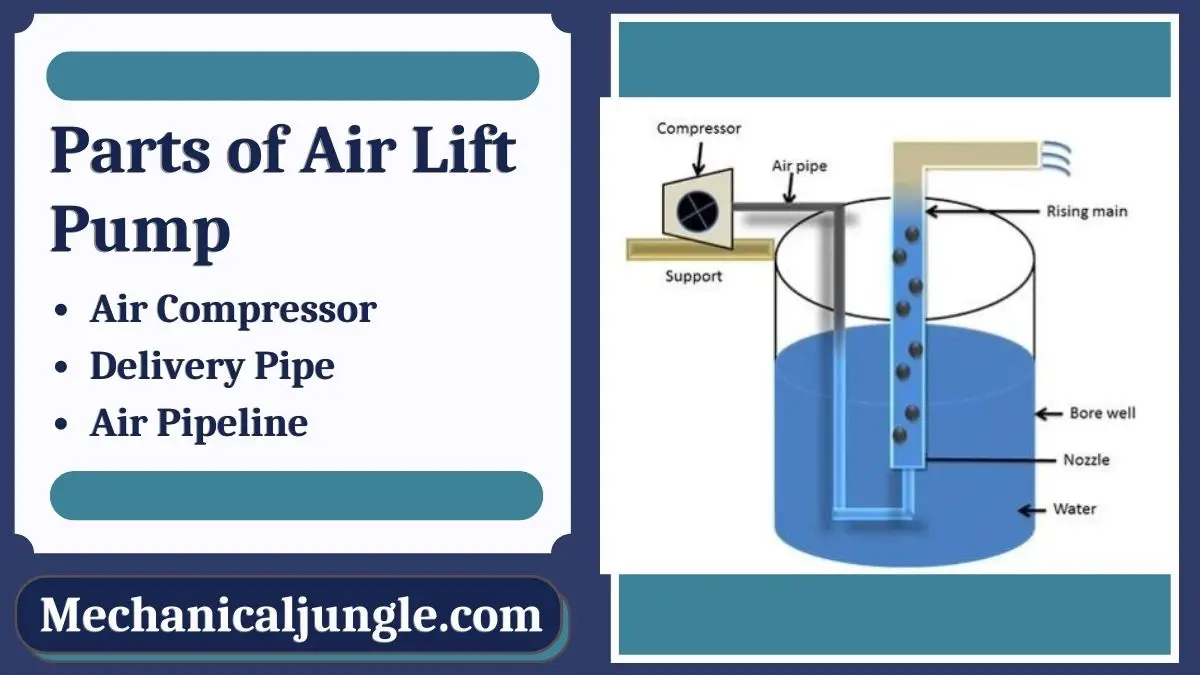
An airlift pump is a pump that has low suction and moderate discharge of liquid and entrained solids. The pump injects compressed air at the bottom of the discharge pipe which is immersed in the liquid. The compressed air mixes with the liquid causing the air-water mixture to be less dense than the rest of the liquid around it and therefore is displaced upwards through the discharge pipe by the surrounding liquid of higher density. Solids may be entrained in the flow and if small enough to fit through the pipe, will be discharged with the rest of the flow at a shallower depth or above the surface. Airlift pumps are widely used in aquaculture to pump, circulate and aerate water in closed, recirculating systems and ponds. Other applications include dredging, underwater archaeology, salvage operations and collection of scientific specimens.
The only energy required is provided by compressed air.compressor or a blower. The air is injected in the lower part of a pipe that transports a liquid. By buoyancy the air, which has a lower density than the liquid, rises quickly. By fluid pressure, the liquid is taken in the ascendant air flow and moves in the same direction as the air. The calculation of the volume flow of the liquid is possible thanks to the physics of two-phase flow.
Airlift pumps are often used in deep dirty wells where sand would quickly abrade mechanical parts. (The compressor is on the surface and no mechanical parts are needed in the well). However airlift wells must be much deeper than the water table to allow for submergence. Air is generally pumped at least as deep under the water as the water is to be lifted. (If the water table is 50 ft below, the air should be pumped 100 feet deep). It is also sometimes used in part of the process on a wastewater treatment plant if a small head is required (typically around 1 foot head).
The liquid is not in contact with any mechanical elements. Therefore, neither the pump can be abraded (which is important for sandwater wells), nor the contents in the pipe (which is important for archeological research in the sea).
Cost: while in some specific cases the operational cost can be manageable, most of the time the quantity of compressed air, and thus the energy required, is high compared to the liquid flow produced.
Conventional airlift pumps have a flow rate that is very limited. The pump is either on or off. It is very difficult to get a wide range of proportional flow control by varying the volume of compressed air. This is a dramatic disadvantage in some parts of a small wastewater treatment plant, such as the aerator.
this pumping system is suitable only if the head is relatively low. If one wants to obtain a high head, one has to choose a conventional pumping system.
because of the principle, air (oxygen) dissolves in the liquid. In certain cases, this can be problematic, as, for example, in a waste water treatment plant, before an anaerobic basin.
A recent (2007) variant called the "geyser pump" can pump with greater suction and less air. It also pumps proportionally to the air flow, permitting use in processes that require varying controlled flows. It arranges to store up the air, and release it in large bubbles that seal to the lift pipe, raising slugs of fluid.
"Airlift calculation by Sanitaire (pdf document)" (PDF). sanitaire.com. 2012-01-05. Archived from the original on 2012-01-05. Retrieved 2022-06-25.link)

The system allows the aspiration of the bentonitic muds from the fund of the excavation. The employment is recommended when in the mud it is present an high percentage of sand and for this reason it constitutes a valid alternative to the traditional pumping systems. The aspiration happens through a pneumatic ejector that allows an output up to 40 m3/hs. This solution is extremely practical for transport and handling in the yard, as it needs no additional work, except the air-compressor. The machine can also be supplied on a crawler undercarriage to make autonomous its move.

Pump deeper and faster with the Power Booster ™. Pressure Lift Corporation is your source for strong and reliable power-boosting pump equipment and accessories. Based in Lewisville, Texas, we are proud developers of the Power Booster, a pump that provides vertical lift with virtually no limits. Our equipment serves professionals across many different industries by conveying fluids in a safe, efficient, and quick manner. Protect your bottom line, save time, and increase productivity with our power-boosting pump.
The Pressure Lift Corporation Power Booster is a vacuum-assisted pumping nozzle that simplifies the transference of liquids and highly viscous materials. It provides nearly limitless vertical lift and distance capability while pumping a wide range of materials. From wastewater and drilling mud to heavy sludge and oil, this power-boosting pump is a reliable, user-friendly addition to any equipment roster.
When you equip your cleanup crew with the Power Booster, you are able to streamline your procedures, maximize your productivity, and increase your bottom line. This power-boosting fluid pump moves viscous materials, including those with debris, with ease. All of our products are proudly designed and manufactured in the USA.
Our specially designed nozzles use the principles of vacuum pumps and air pressure to provide a seamless fluid conveyance solution that saves time, money, and energy. Simply connect the nozzle to a hose and a compatible air compressor, and watch your extraction system become a power-boosting water pump. The Power Booster itself contains no movable parts, and its lightweight, aluminum construction ensures easier handling. The result is a handy, user-friendly pump.
The Power Booster creates a high-pressure vacuum out of your hose, which facilitates the transference of heavier, more viscous fluids. As a result, users in the construction, oil, and gas industries have likened this product to a power-boosted mud drilling pump and heavy sludge pump. When you use the Power Booster, you are able to move liquids that also contain debris and gravel.
Since our establishment more than 25 years ago, our business has made a point to adapt to the ever-changing demands of our clientele. Recently, we have developed an eight-inch variation of our Air Power Booster. This, along with the six-inch nozzle, has served professionals in the oil and gas industry faithfully. The Power Booster truly is in a class of its own. Our patented design facilitates the use of lightweight Power Booster accessories while also retaining dependable durability and intuitive ease of use.
Whether as a handy water-pump or industrial-grade, power-boosted heavy sludge pump, the Power Booster will serve you faithfully for years to come. The owner has spent more than 45 years developing and refining the designs for our products. Our commitment to our products illustrates our dedication to fulfilling your fluid transference needs.
Since 1933, Gorman-Rupp has manufactured the high-performance, high-quality pumps and pumping systems required for lasting service in the municipal, water, wastewater, sewage, industrial, construction, petroleum, mining, fire, and OEM markets.

Air lift pumps are also known as mammoth pumps, gas lifts or Löscher pumps, and are used for lifting liquids laden with solids. For this purpose a gas is injected below the liquid level, via a compressor, into the pipe, which is immersed vertically into a liquid (also see Type of pump).
The function of air lift pumps is based on the lift action of a mixture of liquid and gas (seeTwo-phase flow). They can therefore only be used in pump systems with sufficient geodetic head differences.

By Clifford E. Jones – There is no reason to pay a lot of money for a water pump when this DIY airlift pump design will do all you want. The cost is very low. The materials list is for a 100-foot well; adjust this to meet your well depth.
To start, you will need to remove the well cap. If damaged, build or buy a new one. Keep the well clean. Put four holes in the well cap. (Illustration 1.) Two holes for vents, one for the 1 ¼” discharge pipe, and one for the ½ air pipe. Screen the vents.
The discharge pipe is 1 1/4” diameter, the air pipe is 1/2“ diameter. Use adhesive and two small stainless steel screws at each connection. Make the 1-1/4” pipe the same length as the well depth. Put the end furthest from the well through the hole you made in the well cap and have it protrude out past the well cap enough to reach over your barrel top. (See illustration 2).
Now put the 1-1/4” clamp on top of the well cap. This will eventually keep the pump from dropping down the well, so make it tight and be sure it won’t slip down the hole in the well cap. Next, make the ½” line. Starting at the bottom, put on two 90 degree elbows and a 30” piece of pipe and insert it up into the 1-1-4” pipe and clamp both pipes together (Illustration 3).
Now hook up the two elbows on the 1-1/4” pipe, putting a piece of pipe over to your barrel and a short piece to point down into the barrel. Don’t poke the end of the discharge pipe into the barrel. The air needs to escape.
What is happening here is air is pumped down the small pipe and released into the larger pipe forming bubbles which rise and capture the water and bring it to the top.
You may not have a large well and can get by with a ¾” discharge pipe and a 1/4” air line. Just don’t block the bottom of the large pipe with the small one. Leave room for the water to enter.
This article wouldn’t be complete without something on the air compressor. The main effort is to put some air down the small line that is only blocked by water. Any compressor capable of pumping up an auto tire will do. Air volume is more important than great pressure. I used an automobile air conditioner pump with great success but it did pump oil, and that isn’t good. Get yourself a good air compressor.
This airlift pump design may seem like a poor man’s pump, but there are some advantages over other pumps. It won’t freeze; you can do it yourself; any servicing is done at the compressor and not down the well; and if you just happen to live past the power company, you can still have the water and not cost you an arm and a leg.

Using compressed air is one such well development method. Most of today’s water well drill rigs come equipped with rotary screw air compressors. Reciprocating piston air compressors have been going by the wayside dating back to the mid-1980s.
“Once you know these (rotary screw air) compressors, they’re pretty simple,” says Garth Owens, president of Drill Tech Drilling & Pump Inc. in Chino Valley, Arizona. “It’s not rocket science, but it is a precision unit.”
With approximately 15 rotary screw air compressors (two piston booster compressors) on six drill rigs or as auxiliaries on 10 pump hoists, Owens has learned the mechanical intricacies of them. He has rebuilt the compressors, changed their gear sets, and replaced them on rigs while passing along his knowledge to others in the industry.
“A lot of guys who are drilling don’t even have the right air to develop a well and they’ll throw a pump down there and just try to pump out the mud,” says Garth’s son, Nick, the manager at Drill Tech. “It destroys pumps and you’re never getting that mud wall cake off the walls behind the gravel pack to really get what the well’s producing.”
“You can drill too big of a well to where the annulus is too big, and you can’t get through the gravel pack to get the walls clean. That’s a big problem. A lot of guys think the bigger the hole they go, the more gravel the better, which isn’t necessarily good because you can never get enough annular velocity to get through the gravel pack and get that mud cake off. So, you’ve got to step back and look at the big picture of your annulus to your casing size to your gravel pack.
Today’s standard rotary screw air compressor rating is at least 900 cfm or 1000 cfm/350 psi. Thirty years ago, the standard was 450 cfm/250 psi or 600 cfm/250 psi.
For example, a 750 cfm/125 psi compressor is half the compressor of a 750 cfm/250 psi compressor because the contractor is compressing the air twice as tight. Therefore, with a 750 cfm/350 psi compressor, the contractor is compressing the air an additional 50%.
To decrease the uphole velocity of 3000 feet per minute, some contractors use drill foam to clean the well at half the amount, 1500 feet per minute. “If you’re using foam and you’re filling that void, you’re taking half of that void away,” Garth Owens says. “You’re using half the air because you’re filling that void with an artificial substance. It’s going to foam up and blow out and then it’s going to evaporate and go away.”
The company conducts simultaneous swab-and-airlift with its double-swabbed development tool (see right photo) or uses high-velocity horizontal jetting.
The double-swabbed tool has perforations between the two swabs. Airlifting typically occurs through the drill pipe “from which the development swabs are suspended, so as the swabbing action brings suspended solids into the well, they are purged by the simultaneous airlift system,” writes Marvin F. Glotfelty, RG, in his book, The Art of Water Wells.
“The air comes out of the end of the drill pipe, comes up and hits that rubber swab which is the same diameter as the casing,” Garth Owens says, “and therefore all that air has to go out the perforations, blows into the gravel pack, spins that around in there, and cleans the gravel pack and cleans the borehole. Then the water comes up through the gravel pack and comes back to the perforations above your swab and comes out the top of the well.”
“We’ll actually create a vacuum and pull it between sections there,” Nick Owens says. “That’s why there’s a rubber swab above and below the holes. Typically, if you want to do an air swabber, you don’t need the rubbers because you’re just blowing it out through the perforated screen into the formation.”
The company’s high-velocity horizontal jetting tools allow it to adjust the amount of air it needs to push through them. “That way it’s blowing the air through the perforated screen, through the gravel pack, and then we’re trying to develop all that mud off there if it’s a mud hole,” Nick Owens says.
The company has an additional high-velocity jetting ball tool with approximately 20 holes each drilled to 3/16 inches around it. A high-pressure pump is used to pump freshwater down the well at 2000 psi.
“That will not only churn and turn that gravel, but it places that mud thinner all the way back to the borehole to knock off the wall cake,” Garth Owens says, “and once you’re done pressure jetting it, then you’ll come back and re-swab it and RC it all back out of there.”
Drill Tech, which had a backlog of approximately 100 wells and 30 pumps to install as of late July, stresses it all starts with the design of the well, drilling it correctly, using the right products, and not overusing polymers.
“If we’re RC drilling, we’ll mud up the top and then we’ll case the top off,” Nick Owens says. “There’s some wells out here where we live where the top 300 feet is all alluvium and there’s no water in it. We’ll mud those up, we’ll set a 300-foot surface casing, and we’ll RC drill the bottom out with just pure water because it’s just solid rock. So, we don’t use any product.
To drive home the importance of using the correct amount of product, Nick Owens recalls a large drilling company that installed two large municipal wells 10 years ago in central Arizona. It both drilled with and pumped too much polymer into the wells and was unable to get the polymer out. The wells produced 300 gpm.
“Most guys will just trip their drill pipe straight in, blow it straight up the hole, and they’re done,” he shares. “But you’ll get a lot more water out of your well, you’ll pump a lot less sand, and you’ll have a much better production well with a higher pumping level if you clean that formation out and get every bit of that mud that you put in back out again. The only way to do that is with pressure through the perforations.”
While drilling in July in California, Garth Owens also noticed large amounts of gravel being put into large diameter wells drilled using the mud rotary method. “They think that the bigger the hole is, the more gravel they put in, the better it is, which is not true. What they don’t get is the bigger the hole gets, the worse development job you can do.
“You design with maybe a 10 percent passing of sand,” he says, “and then you want to go down there and develop it until that 10 percent gets down to 0.5 percent or 0.25 percent. You want to airlift develop that until you’ve blown out everything, you’ve agitated it, washed out the gravel, washed off the wall cake, and then the ground itself and those fines come out of there.
“If you don’t do it right, you can spend three or four days pumping sand because the gravel is too coarse. You put in too coarse of a filter and the sand just keeps flowing. It takes forever, if it ever does stop. Too coarse of a sand and it’ll never stop.”
However, unlike with a reciprocating piston air compressor, Garth Owens cautions against closing the downhole valve, build maximum pressure, and jerk the valve open with a rotary screw air compressor.
“Because on a piston compressor, you just have a receiver tank that just holds air,” he says, “and you can pressure it up to 250 to 300 pounds and jerk the valve open and that big surge of air is what blows out silts and rocks when it won’t do it when steady drilling.
For years, automatic transmission fluid (ATF) was the standard for lubrication on compressors. Today, synthetic compressor oil is used because they must run at about 225 degrees to 275 degrees to vaporize the water as it sucks moisture out of the air when drilling. “It sucks all that moisture into it and it rusts up all the bearings and gears,” Garth Owens says, “so by turning the thermostat up so hot, it vaporizes and burns the condensation out of it.
“Typically, there’s three thousandths max tolerant in a screw compressor, so you really have to keep your air filters clean, your oil filters clean, and your oil good. When that tolerance starts to get loose, when you start getting a bearing wearing out or one of your screws starts wearing into the impeller of the compressor, when that tolerance starts to get loose at all, typically your oil temperatures skyrocket tremendously. It’ll run at 200 degrees for 10 years and then all of a sudden, you’re wondering why it’s running at 275 degrees and trying to cook the hoses off your rig.”
The first indication is typically losing a bearing when the oil temperature begins climbing with the tolerances getting loose. “You either have steel on steel friction, or the tolerance is so loose that after you’ve compressed this air and oil, it scoops up the air and oil and pushes it through the screw,” Garth Owens says.
“Because the tolerance is so loose, it squirts right back out of it and now you’ve built more friction, more heat, and it has to scoop it back up again. So as the screw compressor starts to go out, the volume of air starts dropping and the temperature of your oil starts increasing. Those are your first indications that when the oil temperature is coming up, you’ve got screw damage, and when your cfm of air goes down, you have damage.”
Marvin F. Glotfelty, RG, discusses various types of well development (including swab-and-airlift) and physical attributes of the well that will be impacted by the various development methods in an NGWA: Industry Connected video.


 8613371530291