
air lift mud pump brands

The pumps PM are made of corrosion-proof materials conforming to conditions for conveying potable water (GENOVA system). During air flow cut-off the pump’s construction provides separation of the supply system from the media pumping zone by means of a diaphgram perforated valve, closed by hydrostatic pressure.
The pumps are highly reliable and easy to assemble owing to the use of PVC hose as an intake end. The hose can be formed depending on the shape of the tank.
The capasities of the pumps (specyfied in laboratory conditions for clean water and constant depth Hz=1,5 m) are presented in the diagram showing the dependance of air demand supplied to the pump on the lifting height “H” of the medium being pumped (see data sent by fax).
The capasity of PM 110, at immersion depth Hz= 4m, is 15-20m3 (at H=0,5 m). The pumps can operate in a complex system allowing for multiplication of capasity. The lenghts of ends, intake L2 and exhaust L1, and air supply hose are specyfied by the buyer. We suggest the purchase of the very “heart” for individual assembly.

Distributor of engineered fluid handling pumps, packaged pumping systems, repairs, parts, & integrated pump control systems. Mud pumps, chiller/condenser pumps, plumbing pumps, boiler feed systems, in-line circulators, condensate systems, sump & sewage pumps, end suction pumps, submersible sump & sewage, non-clogs & grinders, self primers, packaged lift stations, variable speed pump systems, metering pumps, chemical injection systems, chemical mixing systems, peristaltic pumps for chemical feed, high viscous & shear sensitive fluids, self primers, stainless steel, trash pumps, hot oil pumps, vertical turbine pumps, sanitary pumps, marine pumps, industrial pumps, ANSI end suction, vertical cantilever, double suction, non-clogs, progressive cavity pumps, helical gear pumps, well pumps, lab pumps, hose pumps, control valves, check valves, air release valves, tanks, pressure vessels.

features 2-stage, 44 to 1 gear reduction with a large diameter output gear and heavy duty ball bearing construction. Often referred to as Mud pumps or Sludge pumps, diaphragm pumps are designed to pump mud, slurry, sewage, and thick liquids that have the ability to flow. Koshin Diaphragm pump Honda GX120 OHV gasoline engines. Built-in molded polyurethane flapper/check valve assures self-priming to 20 feet after initial prime. Each unit includes a 3" NPT steel suction strainer, two 3" NPT nipples, and wheel kit with 10" semi-pneumatic transport wheels for portability. Pumps are designed for use with non-flammable liquids which are compatible with pump component materials. Suction and discharge port size cannot be reduced.
Suction and discharge port size cannot be reduced. Due to positive pumping action of diaphragm pumps, by all mfr"s, the discharge is recommended to only be 25FT long unless oversized. Discharge can not be restricted. There is no relief valve.

15 Models below. Made in USA. Gas, Diesel or Electric diaphragm pump, or mud / sludge pump. Easily maneuverable, the gas diaphragm pump is built for performance; Ideal for seepage dewatering, high suction lift, cleaning septic tanks, pumping industrial waste and marine tanks, small wellpoint systems and dewatering in sandy, muddy waters. Honda or Briggs gasoline engine or Electric diaphragm pump with motor.
Diaphragm Mud pump Suction & discharge port size cannot be reduced. Cast aluminum construction with thermoplastic rubber diaphragm. Also called a mudhog. 90 degree rotatable base on all models to fit through narrow gates. As a alternate in a centrifugal pump dredge pump design see 316F-95 2" mud pumps. Trash pumps, centrifugal Dredge Pump. Hoses and accessories.
If you are supplying pump supplies, you can find the most favorable prices at Alibaba.com. Whether you will be working with piston type or diaphragm type systems, reciprocating or centrifugal, Alibaba.com has everything you need. You can also shop for different sizes air lift pump wholesale for your metering applications. If you operate a construction site, then you could need to find some concrete pump solutions that you can find at affordable rates at Alibaba.com. Visit the platform and browse through the collection of submersible and inline pump system, among other replaceable models.
A air lift pump comes in different makes and sizes, and you buy the tool depending on the application. The pump used by a filling station is not the one you use to fill up your tanks. There are high flow rate low pressure systems used to transfer fluids axially. On the other hand, you can go with radial ones dealing with a low flow rate and high-pressure fluid. The mixed flow pump variety combines radial and axial transfer mechanisms and works with medium flow and pressure fluids. Depending on what it will be pumping, you can then choose the air lift pump of choice from the collection at Alibaba.com.
Alibaba.com has been an excellent wholesale supplier of air lift pump for years. The supply consists of a vast number of brands to choose from, comes in different sizes, operations, and power sources. You can get a pump for residential and large commercial applications from the collection. Whether you want a water pump for your home, or run a repair and maintenance business, and need a supply of air lif pump, you can find the product you want from the vast collection at Alibaba.com.therther it is for refrigeration, air conditioning, transfer, or a simple car wash business, anything you want, Alibaba.com has it.
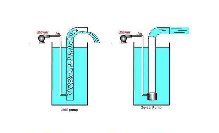
Air Lift pump or Air Lift pump is one of the simplest equipment in the field of wastewater treatment and aeration of aquaculture pools, which with the help of air pressure, tries to transfer fluid to the top of the ponds. Airlift pumps or air pumps are designed on the basis that the presence of air bubbles in the fluid will reduce their density and eventually lead to their upward movement. Seven Industrial Group; Manufacturer of airlift pumps and other water treatment equipment designs and manufactures this group of products in compliance with various standards. In the following, we will provide a comprehensive guide including how air pumps work, standards and important points in the design, production and manufacture of airlift pumps and everything you need to know about the price of Air Lift pumps and their purchase.
An airlift pump is a pump with low suction power that consists of two very simple pipes that are transferred from a compressed air pipe by a compressor or blower to the lowest point of the pond or treatment plant or pool and in the next pipe water droplets or Sewage moves up with the air. This type of pump actually reduces the density of the fluid by moving air into the sewage and fluid in the ponds and moves easily to the highest level of the pond.
To better understand and become more familiar with the Air Lift pump, it is better to first describe how this type of pump works and introduce each of the steps that go through it. The operation of the airlift pump is as follows:
The entry of air into the fluid or sewage creates multiple bubbles that reduce the density of the fluid and move upwards through the second pipe of the pump.
Due to aeration and bubbling in the sewage and its transfer to the top, solid particles deposited in the floor may also move upwards. A very important issue in aeration or transfer of sediments by this pump is the non-use of mechanical or electronic energy, which is a great advantage for it.
Due to their simple structure, Air Lift pumps have low suction power and low fluid transfer speed upwards. Therefore, different types of this pump are designed. We introduced its common type in the first part of the text and explained how it works. In order to improve and increase the efficiency of the device, changes were made in its structure and another type called geyser pump was designed and produced.
In order to improve the suction power and transfer of air and fluid flow upwards to sedimentation ponds or aquaculture ponds, changes were made in the structure of conventional air-pump pumps. geyser pump is actually an improvement of old pumps that in their general structure, in addition to air transfer pipes, a kind of pipe is also considered as an air supplier. This pipe eventually causes fluid and air in the transfer pipe create larger bubbles. The formation of larger bubbles and their presence in the sewage or water in the ponds and the liquid source greatly affects the density reduction and therefore the speed of their transfer to the highest level of the pond increases.
In designing an airlift pump, it is necessary to consider several very important issues in order to increase the efficiency of this group of equipment. One of the most important things in designing an air lift pump is the height and length of the pipes. The air transfer pipe should be considered at the height of the pond and the liquid source in order to perform aeration and fluid transfer from the lowest point. In addition, it is necessary to determine the material of the pipes according to the organic matter in the wastewater to prevent corrosion and decay. Stainless steel and fiberglass, cast iron and composite are among the materials that can be selected according to the conditions of sewage and the environment of installation and use of Air Lift pump.
Seven Industrial Group, as the oldest manufacturer of water and wastewater treatment equipment, has designed and manufactured Airlift pumps in its activities. It should be noted that in the process of manufacturing the airlift pump, the environmental conditions and the treatment plant are considered and the required standards are determined by the development and research team and a group of professional engineers, and finally the design is done. To know the features of each of the products in this collection, experts are ready to provide the necessary advice before buying an airlift pump.
The price of airlift pumps, like other water and wastewater treatment equipment, is determined by various factors, and that is why the variety of these pumps is high. Pipe body material, pipe height and size, type of pump and compressor, etc. are among the factors that affect the price of the airlift pump. To inquire about the price of Air Lift pump, all you have to do is contact the experts of Seven Industrial Group through the communication channels mentioned at the bottom of the page.
The reasons for using air pumps are so varied that in some cases they may be used to transfer sludge deposited in sedimentation ponds or to aerate aquaculture ponds. It is very important to note that if you use this pump to transfer sludge and sediment from the bottom of the ponds, it is necessary to consider the diameter of the fluid transfer pipes up large enough.
The use and purchase of airlift pumps in the field of water and wastewater treatment is very high, the main reason for its great popularity is the numerous advantages of this equipment, some of which are:
Despite the many advantages of this type of air pump, there are limitations in their use, in other words, like other equipment, it has disadvantages, some of which are:

Since 1933, Gorman-Rupp has manufactured the high-performance, high-quality pumps and pumping systems required for lasting service in the municipal, water, wastewater, sewage, industrial, construction, petroleum, mining, fire, and OEM markets.
According to relevant research, it is clear that for a traditional mud pump, there will be blockage and wear during the dredging process because the flow cross-section of the blade is so large that its concentration is limited. Compressed air serves as the power source for air transportation, which can pump and transport liquid or mud through the combination of buoyancy, friction, and vacuum effects (Fu and Yan, 2004; Pei and Liao, 2010). To the best of our knowledge, the airlift system has many advantages, such as low cost, easy operation, simple configuration, no pollution to the environment, and less blockage (Chen et al., 2009; Pei and Tang, 2015). Therefore, it can be considered that the air transportation system has great potential for river and lake dredging.
Many scholars have carried out research, such as numerical simulation of the mixed fluid in the airlift system and analysis of the relationship between the injection parameter and the performance so that it has a higher matching, and thus, the performance of mud airlift is improved. Huang et al. (2017) performed a numerical simulation to study the effect of the nozzle type, injection depth, and injection hole diameter on the airlift pump, thereby improving the performance of the airlift pump. Alasadi and Habeeb (2017) then performed a numerical simulation study on the airlift pump with traditional and improved air injection devices under different intake flow rates, and the results show that the airlift pump with an improved air injection device can improve performance at higher intake flow rates. In actual operation, sufficient attention should be paid to the critical point of the solid particles carried in the bottom layer. If this is not given, it will cause blockage in the pump which will affect the performance and cause safety accidents in severe cases. When researchers study critical characteristics, they are mainly conducted from the perspective of experiments and rarely involve theoretical models. Taleb and Al-Jarrah (2017) performed an experiment to study the effect of the submergence ratio and air injection hole diameter on the performance of the airlift pump. The results showed that the performance of the airlift pump increased as the submergence ratio increased, while an injection hole diameter of 4 mm gave the highest performance. Oueslati A performed an experiment under many operating conditions, and proposed a theoretical model taking into account the air humidification and liquid temperature. The results showed that the proposed model is in good agreement with the experimental results. Fujimoto and Murakami studied the critical conditions of a mud airlift pump and obtained a model of the critical water flow rate for lifting solid particles at the bottom of the pump. By using this model, results that are consistent with reality can be obtained (Fujimoto et al., 2004). On this basis, our research team expanded the suction distance and obtained the rule of critical particle detonation. It needs to be clear that the aforementioned studies are only for water–solid two-phase flow (Tang et al., 2012). Fujimoto and Nagatani then used the aforementioned working conditions to analyze the critical conditions of particles transported in the three-phase flow. The research results show that in the three-phase flow, the starting of particles is easier, but the corresponding theoretical model is not proved (Fujimoto et al., 2005). In application, because of the constraint pressure (Pei et al., 2010; Hu et al., 2013), the particles are often compressed when they are deposited at the bottom, which makes it difficult to start the particles. At the same time, the airlift is caused to fail, but scholars rarely conduct research on this aspect.
In this study, the research is carried out. The interface selects the inlet of the airlift pump to divide the mixed water into two fluid phases, one is a water–solid two-phase flow, and the other is a gas–water–solid three-phase flow. To satisfy the actual dredging, the medium used in this study is round river sand. Based on this, the critical conditions of the three-phase flow and two-phase flow are analyzed, and the relationship between the key condition and chip compaction is analyzed. For discussion, the research result of this study can provide a reference for other researchers to study related theories.
Because the volume fraction of the solid flow cannot be calculated in the calculation, the mixed water can be regarded as a gas–water two-phase flow. On the basis of full research and analysis of the research results of Tang et al. (2012), the volume fraction of airflow can be clarified.
Figure 3 shows the calculation results of the key model, where calculated JG is equal to JG,cri. It is clear that in the water–solid two-phase flow, the critical water flow rate does not change. Therefore, JL,LS,cri ≥ JL,3,cri can be obtained. Based on this, it is possible to clarify that the condition under which the particles are lifted smoothly from the beginning of the entire flow is JL ≥ JL,LS,cri, and it will affect the critical starting condition of the particles. Based on the existence of air expansion, the mixed fluid in the gas–water–solid three-phase flow has a lower density, so JL,3,cri is smaller than JL,LS,cri, compared with the water–solid two-phase flow. Therefore, it is clear that to make the start of the particles easier, the length of the two-phase flow should be reduced. This conclusion is consistent with that of other researchers, that is, the performance of air transport can be improved by moving the intake position downward (Hattaa et al., 1998; Mahrous, 2013).
Analyzing Figure 3, it is clear that when JG,cri is increased, JL,3,cri will be reduced. After reaching the inflection point, JL,3,cri will decrease as JG,cri decreases. Therefore, by increasing JG,cri, the density of the mixed fluid can be reduced, so that the start of the particles becomes easier. Near the inflection point, because the gas value is large, the movement of the particles is mainly controlled by the water phase. From this, it can be clear that the performance of the airlift will be affected by working conditions, and it is necessary to reduce the air mass and then change the flow pattern in the tube, so that it can change from circular flow to elastic flow. It needs to be clear that this change is irreversible, that is, after reaching the inflection point, JL,3,cri will decrease with the decrease of JG,cri. According to the related research results (Hanafizadeh et al., 2011; Tang et al., 2016), the critical airlift of mud is opposite to the existence of the inflection point. In engineering applications, the inflection point needs to be moved down as much as possible. Comparing and analyzing the critical strength of particles with different diameters can be clear (Figure 3A). When the particle diameter is increased, JL,LS,cri and JL,3,cri will rise accordingly. The reason for this phenomenon is that increasing the particle diameter will increase the solid phase slip. In Figure 3B, it is clear that when the particle density increases, JL,LS,cri and JL,3,cri will rise accordingly. The reason for this phenomenon is that increasing the average density of the mixed water will reduce buoyancy. In addition, when increasing the particle density and diameter, the inflection point will move to the right (Kassab et al., 2007).
In the aforementioned model, particles need to be placed in the tube. However, in practical application, the particles will first deposit at the bottom of the water, and then they will be affected by the static chip retention effect. Obviously, the working conditions are different from those assumed by previous research. To be consistent with the practical situation, the research object selected in this study is particle B which is closest to the bottom of the pump. Figure 4 shows the force acting on particle B.
The instantaneous rate, at the moment when the particle is lifted, can still be regarded as zero. We get uS =0 and duS/dt=0. Then, the critical water flow rate uL can be calculated by Eq. 23.
Since only single particle movement is considered during lifting, the volume fraction of the solid in the tube can be ignored, and the immersion ratio γ = L3/L1 is introduced, then Eq. 23 leads to
Compared with the critical water flow model[30] we constructed, it is clear that in this model, we only consider the static chip retention force (static chip retention effect) of the particles, which is in line with the actual engineering. Using the relevant parameters shown in Table 2 to calculate, the results of the model can be clarified (Figure 5). It is clear that with the increase of particle diameter dS and density ρS, the JL,LS,cri only shows a slight upward. On the contrary, when the immersion rate γ is continuously increased, JL,LS,cri will be significantly increased. If the particle density and size are smaller, then the immersion rate γ will control the start of the particle. Analyzing Figure 5, it can be clear that if the static chip retention effect is maintained, JL,LS,cri will be increased quickly. It is concluded that for small and medium particles, the airlift performance will be affected by the static chip retention effect.
It can be considered that in areas such as oceans and lakes, because of their greater depth, the particles have a larger static chip retention force, which causes the start to fail. If the particles are compacted, then it will prevent airlift dredging. Therefore, it is necessary to impact the sand layer before airlift, so that the static chip retention effect can be reduced.
Through the aforementioned theoretical model analysis, it can be concluded that particles are easier to start in the gas–liquid–solid three-phase flow than in the liquid–solid two-phase flow. To verify this theory, critical experiments are carried out in two-phase flow tubes and three-phase flow tubes with river sand particles as the lifting medium, as shown in Figure 6.
First, the bracket is placed 5 mm from the entrance so that it is in the center of the tube. Second, particles are placed in the center of the tube to adjust the immersion depth so that the immersion rate can match the preset value. Third, the valve of the air compressor is slowly opened to allow the airflow to rise slowly. When the water at the outlet of the tube overflows, the valve is immediately closed. At this time, the critical water flow rate of the lifting solid JG,L,3,Cri can be calculated. While increasing the air volume, the distance between the particles and the support frame will gradually increase. At this time, the critical water flow rate JL,3,Cri and the corresponding air volume value JG,S,3,Cri can be calculated. In the two-phase flow experiment, a bracket is placed 5 mm below the air inlet, and the particles are placed on the support frame. Under this condition, the critical values JG,L, LS,Cri, JG,S,LS,Cri, and JL,LS,Cri of the two-phase flow are recalculated. Table 3 shows the calculation results.
If the immersion rate does not change, there is no significant difference between the critical values JG,L,LS,Cri of the two-phase flow and the critical values JG,L,3,Cri of the three-phase flow. When the immersion rate is equal to 0.8 and 0.3, respectively, the critical value of JG,L,LS,Cri and JG,L,3,Cri are approximately equal to 0.012 m/s and 0.019 m/s, respectively. Therefore, it can be considered that the key characteristics of the water–gas lift will not be affected by the position of the particles in the tube or the size of the particles. However, it needs to be clear that there are differences between the key characteristics of a slurry water–gas lift and the key characteristics of a gas lift. Compared with JG,S,LS,Cri of the corresponding particles in the two-phase flow, the critical air value of the particles in the three-phase flow, JG,S,3,Cri, is significantly lower, and when the temperature is increased, it will increase accordingly. Analyzing Table 3 shows that under the established conditions, compared with JL,LS,Cri, JL,3,Cri are always lower. Therefore, it can be considered that the water–solid two-phase flow has a greater impact on the critical characteristics of air transportation.
Comparing the experimental results and the calculated results, it is clear (as shown in Figure 7) that the experimental value of the critical water flow rate for lifting the solid is lower than that of the calculation result when only lifting the particles. This situation occurs because the tube and the pump will coalesce, expand, rupture, and re-aggregate. The bubbles will move periodically, causing mixed fluid instability along the axial direction when it rises. Ascending, its oscillation characteristic is ascending-descending-ascending, and compared with descending motion, the ascending motion is more intense. According to the results of other researchers and ours, it can be inferred (Hu et al., 2012; Hu et al., 2015) that the basic feature of a slurry airlift is the oscillating upward motion of the mixed fluid, which will cause a transient vacuum, so there will be resistance. If the particle’s fluctuation reaches its peak, then the particle’s activation state can be advanced. Figure 7 also shows that if the immersion rate is lower, the mixed fluid will have more prominent oscillation characteristics, which will result in a higher instantaneous vacuum. To confirm these phenomena, high-speed cameras can be used.
Due to the effect of gravity, the particles will be affected by the static chip retention effect when they are deposited at the bottom of the water. When we are conducting research, we put sand particles on the bottom of the pump in advance (Figure 4). At this time, the sand will be closely arranged and in a double-stacked state. To maintain the static chip retention effect, the particles need to be placed in the water continuously for 7 days. Then we adjusted the water tank and preset the immersion rate. The particles in the center of the upper layer are the object, and the key experimental steps are repeated. Based on this, we can get JG, L, LS, Cri, JG, S, LS, Cri, and JL, LS, Cri. The research results show that the particles cannot start when the air compressor valve is adjusted from close to the maximum gas flow. Therefore, it can be considered that the static chip retention effect is obvious at the bottom. Even if the pump has a large water value and the resistance imposed on the particles is small, the static chip retention force cannot be overcome, thus making it impossible to carry out an airlift. To clarify the experimental results of JL,LS,Cri, we connected the outlet of the airlift pump to a high-power centrifugal pump. Table 4 shows the comparison results of theoretical and experimental critical values. Research on the table can be clear, and the calculation results show that the experimental results of JL,LS,Cri are low. Therefore, it can be considered that the fluctuation of water flow and surface defects between adjacent particles (Figure 4) will reduce the compactness, which finally weakens the static retention effect of the chips. Therefore, it can be considered that as long as the static chip retention effect exists, it will affect air transportation, so it is necessary to take measures to eliminate it.
In this study, river sand particles were used as the lifting medium. Based on the static chip retention effect, the critical characteristics of liquid–solid two–phase flow and gas–liquid–solid three-phase flow are explored. The following conclusions can be drawn:
2) In a water-solid two-phase flow, the physical properties of the water and particles will affect the critical water rate. However, in the gas–water–solid three-phase flow, not only will the physical properties of water and particles affect the critical water rate but so will the air rate. Before the inflection point, as the air critical flow increases, the water flow will decrease. After the inflection point, as the air critical flow increases, the water flow will increase. In addition, the existence of the inflection point is not conducive to airlift.
3) On the basis of the constant immersion rate, the critical air rate of the fluid discharged to the pipe outlet is roughly the same. The physical properties of the particles will affect the corresponding water rate and critical air value. In the three-phase gas–water–solid flow, the start of the particles can be easier.
4) When there is a static chip retention effect under water, it is necessary to use auxiliary methods to impact the particle layer or to increase the resistance of the particles, otherwise, it will not be conducive to airlift.
Alasadi, A. A. M. H., and Habeeb, A. K. (2017). Experimental and numerical simulation of an airlift pump with conventional and modified air injection device. J. Eng. 23 (2), 62.
Chen, G., Ning, Y., Tang, D., and Jin, X. (2009). Study on the operation performance of pipeline air-lift system[J]. Min. Metallurgical Eng. 29 (5), 24. doi:10.3969/j.issn.0253-6099.2009.05.007
Fujimoto, H., Murakami, S., Omura, A., and Takuda, H. (2004). Effect of local pipe bends on pump performance of a small air-lift system in transporting solid particles. Int. J. Heat Fluid Flow 25 (6), 996–1005. doi:10.1016/j.ijheatfluidflow.2004.02.025
Fujimoto, H., Nagatani, T., and Takuda, H. (2005). Performance characteristics of a gas–liquid–solid airlift pump. Int. Jonalur Multiph. Flow 31 (10-11), 1116–1133. doi:10.1016/j.ijmultiphaseflow.2005.06.008
Hanafizadeh, P., Ghanbarzadeh, S., and Saidi, M. H. (2011). Visual technique for detection of gas–liquid two-phase flow regime in the airlift pump. J. Petroleum Sci. Eng. 75 (3-4), 327–335. doi:10.1016/j.petrol.2010.11.028
Hu, D., Kang, Y., Tang, C-L., and Wang, X-C. (2015). Modeling and analysis of airlift system operating in three-phase flow. China Ocean. Eng. 29 (1), 121–132. doi:10.1007/s13344-015-0009-z
Hu, D., Tang, C., Zhang, F., and Lin, Y. (2012). Theoretical model and experimental research of airlift device in borehole hydraulic jet mining[J]. J. China Coal Soc. 37 (3), 522. doi:10.13225/j.cnki.jccs.2012.03.014
Hu, D., Wu, X., Tang, C., and Liao, Z. (2013). Experimental study of airlift device for borehole hydraulic jet mining[J]. Mech. Sci. Technol. Aerosp. Eng. 32 (5), 756. doi:10.13433/j.cnki.1003-8728.2013.05.004
Huang, H., Wu, J., Yang, Z., Xue, Z., Ge, W., Wei, W., et al. (2017). A CFD simulation study of air-lift artificial upwelling based on Qiandao Lake experiment[J]. Ocean. Eng. 144, 257–265. doi:10.1016/j.oceaneng.2017.07.048
Kassab, S. Z., Kandil, H. A., Warda, H. A., and Ahmed, W. (2007). Experimental and analytical investigations of airlift pumps operating in three-phase flow. Chem. Eng. J. 131 (1–3), 273–281. doi:10.1016/j.cej.2006.12.009
Oueslati, A., and Megriche, A. (2017). The effect of liquid temperature on the performance of an airlift pump. Energy Procedia 119, 693–701. doi:10.1016/j.egypro.2017.07.096
Tang, C., Ge, R., Hu, D., and Wang, Z. (2016). Experimental study on pipe performance of air-lift system[J]. Chin. J. Hydrodynamics (1), 37–42. doi:10.16076/j.cnki.cjhd.2016.01.006
Tang, C., Hu, D., and Lin, Y. (2012). Experimental study of performance characteristics of an air-lift for conveying river sand[J]. J. Basic Sci. Eng. 20 (3), 440–445.

Step 5. Raise the string of pipe gradually and continue rotating to backwash the entire surface of the screen. If possible, use a pump pressure of 100 psi.
This backwashing method is effective in removing caked drilling mud from the borehole wall. A disadvantage in military field operations is that this method requires a large supply of water. After covering the entire screen with the jetting tool, remove the tool. Remove the sand that has collected in the sand trap with a bailer. Repeat this process until the well stops producing sand. If a significant volume of material is removed during development, you should add more filter material around the screen to keep the top of the grovel pack above the top of the screen.
b. Pump-Surge Method. This backwashing technique involves alternately pumping water to the surface and letting the water run back into the well through the pump-column pipe. Use an airlift pump or a deep-well turbine pump without a foot valve. See Chapter 4 for discussions on pumps. Do not use the permanent well pump for development. Pumping sand could damage the pump. Use the following procedure for this method:
Step 1. Start the pump. As water comes to the surface, stop the pump to release the water. The power unit and starting equipment determine the starting and stopping action of the pump. The effect is to lower and raise the water level in the well intermittently through the screen openings. Periodically, pump the well to remove the sand brought in by surging.
c. Gravity-Outflow Method. Backwashing by gravity outflow involves pouring water into the well rapidly to produce outflow through the screen openings. Inflow through the screen is then produced by bailing water from the well rapidly. This is a slow surging technique requiring several minutes to complete a cycle. If the static water level is high enough to permit pumping by suction lift, you can use a small centrifugal pump instead of the bailer to speed up the work. If there is room in the well casing, connect the discharge side of the pump to a string of small diameter pipe that is lowered into the well. The water added is pumped down inside the screen, creating a turbulence that will help to develop the formation.
d. Pressure-Pumping Method. Occasionally, wells are backwashes by capping the casing and pumping water into the well under pressure. Water is forced outward through screen openings similar to the closed-well method of using compressed air for development (paragraph 7-1f(2)). Pressure pumping is an inefficient method because the desirable surging effect is difficult to produce. You must make sure to seal the casing tightly in the borehole and prevent water from being forced up around the outside of the casing.
Step 2. Start surging slowly and gradually increase the speed until the surge plunger rises and falls without slack. With a rotary rig, lift the plunger 3 or 4 feet before dropping it. When using the sand line, control movement by using the hoist brake and clutch.
Step 3. Continue surging for several minutes. Pull the plunger out of the well and lower the bailer or sand pump into the screen. When the bailer rests on the sand that has been pulled into the screen, check the depth of the sand by measuring on the sand line. Bail all the sand out of the screen.
f. Compressed-Air Methods. Compressed air provides rapid and effective development of wells, using an open- or closed-well method. You can use the standard 350-cfm compressor for developing most wells at a pressure of at least 100 psi. However, a higher pressure is preferable. The 250-cfm compressor will pump water by air lift from 100 to 150 GPM, depending on the submergence and size of the pipes you use. Table 7-2 shows the recommended sizes of pipe and air lines and the pumping rates you should use for various sizes of wells.
Figure 7-3 shows the proper method of placing the drop pipe and airline in the well. Use a hoist line to easily handle the drop pipe. Suspend the air pipe on the sand line. Fit a T at the top of the drop pipe with a short discharge pipe at the side outlet. Wrap a sack around the air line where it enters the drop pipe to keep water from spraying around the top of the well. Discharge from the compressed air tank to the well should be the same size as or one size larger than the airline in the well. Connect a quick-opening valve in the line near the tank. You need a pressure hose, 15 feet long (minimum), for moving the drop pipe and air line up and down.
Step 1. Lower the drop pipe to within 2 feet of the bottom of the screen. Place the air line inside the drop pipe with its lower end 1 foot or more above the bottom of the drop line.
Step 2. Let air enter into the airline and pump the well until the water appears to be free of sand. Start slowly. If all the water is suddenly removed, the casing may collapse in deeper wells, especially when using PVC pipe.
Step 4. Lower the air line until it is about 1 foot below the drop pipe. Open the quick-opening valve so the air in the tank can rush with great force into the well. A brief, forceful head of water will emerge or shoot from the casing and from the drop pipe.
Step 5. Pull the airline back into the drop pipe immediately after the first heavy load of air shoots into the well. Doing so will cause a revered of flow in the drop pipe that will effectively agitate the aquifer.
Step 8. Lift the drop pipe to a position 2 or 3 feet higher in the screen and follow the same procedure. This develops the entire length of the screen a few feet at a time.
Step 10. To complete the development process and thoroughly clean out any loose sand, pull the air line up into the drop pipe and use it as an air lift to pump the well.
(2) Closed-Well Method. With this method, you use compressed air to close the top of the well with a cap and arrange the equipment so air pressure can build up inside the casing to force water out through the screen openings (Figure 7-4).
Step 1. Arrange the equipment as in Figure 7-4, and turn the three-way valve to deliver air down the air line, preferably with the air cock open. This will pump water out of the well through the discharge pipe.
Step 3. Listen to the air escaping through the air cock as the water rises in the casing to determine stability. Close the air cock and turn the three-way valve to direct the air supply down the bypass to the top of the well, forcing the water out of the casing and back through the screen. This technique will agitate the sand and break down any bridging of the sand grains. When the water has been pushed to the bottom of the drop pipe, air escapes through the drop line. You can prevent air logging of the formation by keeping the drop pipe above the well screen.
Step 4. Cut off the air supply and reopen the air cock so the water can reach the correct static level when you hear the air escaping from the discharge pipe or when the pressure stops increasing.
7-2. Dispersion Treatment. Dispersing agents, mainly polyphosphates, when added to drilling fluid, backwashing, jetting water, or water standing in the well, counteract the tendency of mud to stick to sand grains. These agents are procured locally on an as-need basis. Baroid Industries produces Barafos, a white, granular, sodium tetraphosphate thinner and dispersant.
7-3. Rock Development. Use this method to develop wells in rock formations. You can obtain good results by combining jetting with air-lift pumping from a limited zone isolated by inflatable packers. The objective is always to wash out fine cuttings, silt, and clay that have worked into the fissures, crevices, or pores of the rock during the drilling operations. Openings that remain plugged reduce water flow into the well. Develop the well thoroughly to remove all obstructing material. When drilling through limestone formations, use acid to dissolve lime-like cementing material and to open up connections with joints or fissures beyond the borehole wall. However, such operations are rare in military well drilling.
Disinfecting the water used for drilling if you use a mud-based drilling fluid. If you use a synthetic drilling fluid, chlorinate the fluid. However, doing so will break down the fluid and reduce its life.
NOTE: Well casings should extend no more than 12 inches above the pump-house floor on a final-grade elevation and not less than 12 inches above the normal anticipated flood level.
The upper surface of this slab and its immediate surroundings should be gently sloping so water will drain away from the well. You should also place a drain around the outer edge of the slab and extend it to a discharge point that is far away from the well. A well with pipe casing should have a sanitary seal at the top that fills the space between the pump pipe and the well casing. This device consists of a bushing or packing gland that makes a watertight connection.


 8613371530291