
airlift mud pump pricelist

If you are supplying pump supplies, you can find the most favorable prices at Alibaba.com. Whether you will be working with piston type or diaphragm type systems, reciprocating or centrifugal, Alibaba.com has everything you need. You can also shop for different sizes air lift pump wholesale for your metering applications. If you operate a construction site, then you could need to find some concrete pump solutions that you can find at affordable rates at Alibaba.com. Visit the platform and browse through the collection of submersible and inline pump system, among other replaceable models.
A air lift pump comes in different makes and sizes, and you buy the tool depending on the application. The pump used by a filling station is not the one you use to fill up your tanks. There are high flow rate low pressure systems used to transfer fluids axially. On the other hand, you can go with radial ones dealing with a low flow rate and high-pressure fluid. The mixed flow pump variety combines radial and axial transfer mechanisms and works with medium flow and pressure fluids. Depending on what it will be pumping, you can then choose the air lift pump of choice from the collection at Alibaba.com.
Alibaba.com has been an excellent wholesale supplier of air lift pump for years. The supply consists of a vast number of brands to choose from, comes in different sizes, operations, and power sources. You can get a pump for residential and large commercial applications from the collection. Whether you want a water pump for your home, or run a repair and maintenance business, and need a supply of air lif pump, you can find the product you want from the vast collection at Alibaba.com.therther it is for refrigeration, air conditioning, transfer, or a simple car wash business, anything you want, Alibaba.com has it.

By Clifford E. Jones – There is no reason to pay a lot of money for a water pump when this DIY airlift pump design will do all you want. The cost is very low. The materials list is for a 100-foot well; adjust this to meet your well depth.
Now put the 1-1/4” clamp on top of the well cap. This will eventually keep the pump from dropping down the well, so make it tight and be sure it won’t slip down the hole in the well cap. Next, make the ½” line. Starting at the bottom, put on two 90 degree elbows and a 30” piece of pipe and insert it up into the 1-1-4” pipe and clamp both pipes together (Illustration 3).
What is happening here is air is pumped down the small pipe and released into the larger pipe forming bubbles which rise and capture the water and bring it to the top.
This article wouldn’t be complete without something on the air compressor. The main effort is to put some air down the small line that is only blocked by water. Any compressor capable of pumping up an auto tire will do. Air volume is more important than great pressure. I used an automobile air conditioner pump with great success but it did pump oil, and that isn’t good. Get yourself a good air compressor.
This airlift pump design may seem like a poor man’s pump, but there are some advantages over other pumps. It won’t freeze; you can do it yourself; any servicing is done at the compressor and not down the well; and if you just happen to live past the power company, you can still have the water and not cost you an arm and a leg.

An airlift pump is a pump that has low suction and moderate discharge of liquid and entrained solids. The pump injects compressed air at the bottom of the discharge pipe which is immersed in the liquid. The compressed air mixes with the liquid causing the air-water mixture to be less dense than the rest of the liquid around it and therefore is displaced upwards through the discharge pipe by the surrounding liquid of higher density. Solids may be entrained in the flow and if small enough to fit through the pipe, will be discharged with the rest of the flow at a shallower depth or above the surface. Airlift pumps are widely used in aquaculture to pump, circulate and aerate water in closed, recirculating systems and ponds. Other applications include dredging, underwater archaeology, salvage operations and collection of scientific specimens.
Airlift pumps are often used in deep dirty wells where sand would quickly abrade mechanical parts. (The compressor is on the surface and no mechanical parts are needed in the well). However airlift wells must be much deeper than the water table to allow for submergence. Air is generally pumped at least as deep under the water as the water is to be lifted. (If the water table is 50 ft below, the air should be pumped 100 feet deep). It is also sometimes used in part of the process on a wastewater treatment plant if a small head is required (typically around 1 foot head).
The liquid is not in contact with any mechanical elements. Therefore, neither the pump can be abraded (which is important for sandwater wells), nor the contents in the pipe (which is important for archeological research in the sea).
Conventional airlift pumps have a flow rate that is very limited. The pump is either on or off. It is very difficult to get a wide range of proportional flow control by varying the volume of compressed air. This is a dramatic disadvantage in some parts of a small wastewater treatment plant, such as the aerator.
this pumping system is suitable only if the head is relatively low. If one wants to obtain a high head, one has to choose a conventional pumping system.
A recent (2007) variant called the "geyser pump" can pump with greater suction and less air. It also pumps proportionally to the air flow, permitting use in processes that require varying controlled flows. It arranges to store up the air, and release it in large bubbles that seal to the lift pipe, raising slugs of fluid.
"Airlift calculation by Sanitaire (pdf document)" (PDF). sanitaire.com. 2012-01-05. Archived from the original on 2012-01-05. Retrieved 2022-06-25.link)

FloNergia"s FloMov family of pumps are designed specifically for Aquaculture, Aquaponics and Hydroponics applications. They offer a well-engineered dual injector airlift pump solution that uses significantly less energy than conventional centrifugal pumps.
With a wide range of ready available sizes, these pumps serve the need of producers large and small. Custom design solutions are available for an even wider variety of applications and sizes.
[Editor’s Note: The contents of this article have been adapted, with permission, from the innovations of Glenn Martinez of Olomana Gardens Hawaii. The author of this article, Terry Stratton, along with his wife Cyndi and Science & Tech department head Vernon Byrd serve as full-time volunteers at the University of the Nations, Hawaii. The team has over eight years of experience with the campus Natural Farm Training Center that includes building, operating, and teaching about aquaponics and airlift pump configurations for small to medium scale aquaponics systems in Hawaii, and internationally in community development settings. The following article aims to introduce the airlift pump concept and provide a basic overview of design set-up. Several additional resources have been included and further questions can be directed to Terry Stratton t.stratton@uofnkona.edu.]
Water pumps have long been a key component of the small-scale farm and are valuable labor-saving devices that offer a variety of practical applications. Pumps of different types are regularly used for water storage & filtration, irrigation, aquaculture systems, and more. While convenient and useful, pumping water does come at a cost – from the necessary consumption of energy, to the regular maintenance of moving parts. However, new developments in appropriate pump technologies offer options that can save money, increase reliability, improve longevity of equipment, and offer certain other benefits that to be presented in this article.
A conventional water pump uses mechanical rotation to directly pressurize and move water. In contrast, airlift water pumps take advantage of the relatively lighter density of air to lift water. Until recently, airlift pumps were only good for lifting water 10 - 15 cm at most, however Glenn Martinez from Hawaii has since shared with the international community easy-to-build designs that can readily lift water 2 to 3 meters in height. In certain configurations, these airlift designs can lift water much higher, even as high as 30 meters out of a subterranean well. This article will focus on just one of his fundamental configurations, referred to as the ‘pipe-in-a-pipe’ airlift pump (Figure 2). This configuration has been used most often to lift anywhere from 400 to 2000 liters of water per hour to a height of 1 to 4 meters, making it a very useful technology for a wide array of systems. As readers will note, this technology brings particular benefits to aquaponics systems, which is the intended use of these particular designs.
Figure 2: Design specifications of an example Martinez ‘pipe-in-a-pipe’ airlift water pump configuration. Credit: Glenn Martinez of Olomana Gardens Hawaii.
The ‘pipe-in-a-pipe’ airlift pump takes advantage of the fact that air injected underwater will expand as bubbles as it rises to the surface, with a 10% increase in volume from a depth of 1 meter. By confining the bubbles inside of a small diameter vertical pipe, these bubbles will act like a piston, or a syringe plunger, lifting portions of water upward as they rise. The physics involved would fill many technical papers, but the net effect is a strong upward current of water and air. The Martinez design works on the theory that larger bubbles, rather than a cloud of small bubbles, are most efficient at lifting water.
Glenn Martinez, the innovator behind the ‘pipe-in-a-pipe’ configuration of the airlift pump, has been involved for many years in teaching, designing, and building of aquaponics systems at his Olomana Gardens farm in Hawaii, as well as internationally in development settings. He also regularly consults on aquaponics project designs, and several years ago was designing an aquaponics system for a local school where it was going to be expensive to supply electricity. To make the system more affordable he invented (or as Glenn likes to say ‘rediscovered’) a way to lift the water from the fish tank up to the aquaponics grow bed with an innovative air pump configuration. Instead of running electrical conduit in a deep trench across the schoolyard, all that was required was a shallow ditch for the air pipe, quickly dug by the students. In the ditch, a 1-inch PVC pipe was installed, connecting the system to the small 60-watt air compressor located across the way in a lockable classroom. As it turned out, the airlift pump that Glenn came up with had multiple advantages for aquaponics systems and other situations where inexpensive and reliable methods of lifting water are needed.
As the story above illustrates, a conventional water pump requires that electricity be located close to the water source. Electricity and water, as we well know, can be a dangerous combination, especially where children are present. Safety, in regard to electricity in water, should be mitigated and taken seriously in any setting. The Times of India reported that as many as 30 people are killed every day in India by electrocution. One intern working on our projects in the Philippines recently asked us for advice when he was shocked twice with a conventional pump; he simply didn’t have much experience working with electrical devices, including how to arrange extension cords so they remained dry in the rainy season. Ground fault interrupt (GFI) circuits, if they are available, can decrease risk but tend to trip at inconvenient times and require monthly testing. As an alternative, the compressor for an airlift pump can easily be set up at a safe distance from the water to eliminate this potential hazard, decreasing risk substantially. Community development workers may find this particular feature of airlift pumps to be especially beneficial for promoting safety.
One of the great advantages of an airlift water pump is its ability to aerate water as it lifts it. This can be a highly beneficial feature when incorporated into fish production systems, or other scenarios where water quality conditions will benefit from more dissolved oxygen. In some small-scale aquaponics systems with low fish stocking density, the airlift pump alone will provide enough dissolved oxygen to supply the needs of the fish. Used along with a conventional aeration pump and airstones, an airlift pump can provide extra dissolved oxygen and security against the loss of fish from low dissolved oxygen levels.
Submersible water pumps and conventional external pumps are prone to clogging and need periodic cleaning including disassembly. Additionally, the sand and grit that they draw in will eventually wear out components, often necessitating replacement of the pump. The Martinez airlift pump design will not only handle small abrasives but debris nearly as large as the diameter of the inner pipe (1 to 1 1/2 inches). This means that small fish, clumps of algae, uneaten fish food, etc. are simply carried up and out through the pump. In one of our aquaponics systems, we conducted a trial in which we dumped 20 kg of coffee grounds into a tank to test the ability of the airlift to function without clogging; impressively, it passed through with no challenge. The ability to handle gravel and other debris isdemonstrated in this video by Glenn.
At the same time, the air compressor, the most expensive component of the airlift pump, is immune to anything about the water. Freshwater, saltwater, and sludge-laden water are all the same to this pump, as it sits separate from the water source. Additionally, in the case that a conventional submersible pump empties the tank, it will quickly suffer permanent damage from overheating – an air compressor in an airlift pump will just keep on running, ready for the water to return.
Diaphragm air compressors, which are ideal for airlift pumps, are also very easy to repair. Typically, all it takes is a screwdriver to replace diaphragms that wear out every few years. This is simple and much less expensive than replacing an entire conventional pump. Also, changing or moving a compressor can be as easy as unscrewing and reattaching a garden hose.
In some locations, a water pump is vulnerable to theft or vandalism. Since a 1-inch PVC pipe or length of larger diameter hose offers very little resistance to airflow, an air compressor can be located at a distance, locked separately in a building or storage box.
Airlift pumps may also save money by using less electricity. We replaced one 200-watt submersible pump with an 80-watt air compressor to run an airlift. The lower power requirement makes a solar panel powered system more feasible. Glenn has configured conventional pump systems with air injection to make dramatic cuts in the cost of lifting water 8-10 meters high. We don’t have any experience with it yet, but we’ve seen that DIY airlift pumps can also be configured to pump subterranean wells where the resistance to blockage and ease of repair characteristics would be especially valuable.
Larger volume airlift systems are possible and can be accomplished with different sized air compressors with appropriately sized pipes. Our 110-volt compressors range in size from 35 to 110 watts. Compressor selection is determined by several factors including the height the water needs to be pumped and the desired water output volume. The typical aquaponics ‘pipe-in-a-pipe’ configuration only needs an air compressor capable of generating an initial 5 psi (35 kPa) then be able to run continually at around 2 psi (14 kPa). The compressors that run our aquaponics systems produce in the range of 30 to 100 liters of air per minute. You can see from the chart below that the final water volume output of the pump depends not only on the size of the compressor but several other variables (Table 1). The 100 L/min compressor doesn’t deliver the most water because it is pumping higher out of a shallower well.
We aim to turn over the volume of our fish tanks at least once every two hours and these pumps have been more than adequate for that. Pond supply stores or larger aquarium supply outlets may carry the preferred diaphragm style compressors (or alternately, piston air compressors) for this application.
Figure 3: Critical design consideration for the intake portion of the pump, located at the bottom of the sump well. (A.) Air intake ‘slots’ were found to be more effective than many drilled holes - yellow arrows represent air while blue arrows represent water. (B.) The curved bottom will prevent clogging of the intake pipe. (C.) Configuration of the air ‘inlet’ assembly.
It turns out that when the compressor is turned on, that the water between the outside casing pipe and the interior lift pipe is “pushed down” until it reaches the two opposing slits in the interior pipe. The air enters each slit (directly opposite each other) and literally cuts the water like a knife. After cutting the water, the air burst rises upward, lifting the water in the interior pipe all at once. This slug of air lifts all of the water in the interior pipe and comes out as one slug of water. After that first burst of air releases, thus clearing the interior pipe of water, additional water rushes in to fill the bottom of the ‘pipe-in-a-pipe’ pump. Once moving, the water in the interior pipe is 50% air and much lighter, so the air compressor has an easier time pumping the water.
A typical application of the airlift pump, as is the case at our Natural Farm Training Center in Hawaii, requires lifting 500 to 1000 liters of water per hour, available for gravity flow through an aquaponics system (Figure 4). In this case, the airlift pump is an excellent option, aerating the water as it is lifted into the tank above. We have labeled this set up for better understanding of the practical arrangement of the various airlift pump components
This airlift is pumping about 900 liter/hour from an IBC tank to a height of 1.8 meters to a clarifier. The vertical 3-inch PVC pipe is fed water by a ‘T’ connection to the IBC tank (Figure 3). This 3 inch pipe has a cap on the bottom and serves as a kind of ‘sump well’ for the actual ‘pipe-in-a-pipe’ pump. This well pipe, with the ‘pipe-in-a-pipe’ airlift inside, extends 80 cm below ground level (1.5 meters depth would have been better as the volume output of the pump would have increased and we could probably have used a smaller air compressor). The airlift itself is made from a 2-inch outer pipe and a 1.25-inch inner pipe. Water is pumped up and diverted into the tank while air exits out the top.
Figure 4: Martinez ‘pipe-in-a-pipe’ airlift pump configuration for use in a small-scale gravity-flow aquaponics system. This photo was taken on site at the Natural Farm Training Center, Hawaii. Note: Air compressors should always be placed above the high-water level, so no water drains into them when the power goes off.

18 reasons why air lift pumps make so much sense and why you should seriously consider this methodology for your Aquaponics system. (Yes your home Aquaponics system will benefit as well)
Glenn will show you how to make it work, has plan books showing exactly how to do it at your place. Glenn"s air pumps will revolutionise Commercial Aquaponics.
For over 10 years I have calculated the energy efficiency of every airlift pump of which the 3 important data: (energy input driving the air pump, head and volume) were presented,
18 reasons why air lift pumps make so much sense and why you should seriously consider this methodology for your Aquaponics system. (Yes your home Aquaponics system will benefit as well)
Okay.. I will restate this….airlifts are viable alternative to submersible pumps….a method to rid ourselves of them or Turbo them for increased performance and head.
It is not just the purchase cost of the pump…it is the cost of installing the GFI or safety outlet and protective float switches to prevent running dry.
It seems to be is accept fact in literature and practice at colleges that airlifts are only practical for a maximum of 24 inches! We have posted YouTubes of water pumped 24 foot! We do four foot head and pump 1200 gallons er hour with a 60 watt air compressor (Hakko diaphragm)
Not a slogan….the Turbo is our design of adding air immediately above a submersible pump…..for GREATLY added height, twice what the submersible could do alone. We have posted YouTube videos of this and demonstrated a submersible pump and air lift “Turbo” at Murray’s March one day training. Folks built them and took them home. We pumped 15 o 20 feet high with the “Turbo Submersible/airlift combo"
We use compressed air to lift water up to 25 foot, we have tested the water in the tank (using Nitrogen to drive the Oxygen down to less than 1ppm and run the pump, shooting up 12 to 15 feet and collecting the water in a down pipe, and testing it and having raising the water 2ppm in a single pass. We ran the test for 5 minutes and raised the reading to 7ppm. That was in a 75 gallon tank pumping 400 gallons per hour.
The intake filter in our airlift compressors are checked every 90 days…..submerged water pumps every day. We have 7 year old air compressors, only rebuilt 3 in the seven years….customers, not ours. Theirs were 2 to 5 years old and fixed for $40. We throw out most submersibles, because the housing the secures the back bearing is worn out. We can replace the front, the impelller and such, but once the housing is good, trash it.
No airlift is damaged by running dry not is the pump stained or overheated, it just idles till water returns. No switches or float valves. Air lifts can be dropped into a two inch sump well, hard to get protective switches in a two to four inch well.
conclusion 2: unless airlift pump manufacturers procure real (measured, not guessed) performance data and show these in a regular pump chart, they will never obtain credibility.
Show me accurate specs on air compressors and water pumps!!! Good luck!! We test most of our pumps by measuring ACTUAL pumping speed by filling a nice gallon bucket and timing it! We test at a minimum 12 inch, 24 inch, 36” and 48” and publish our results and performance. We even post videos on YouTube of us doing the performance tests!
Wow, what happened to picking up solids? no electrical installation costs? added aeration? Only ONE Pump in the system, the airlift pumps the water and provides the aeration! everyone else has TWO pumps, one water, one air for the fish to breathe! Long life? Less wear and tear? Not being outside getting stolen? Salt water and corrosive environments not an issue with PVC airlifts and no moving parts? Never being damaged by running dry? We use airlifts to transport baby shrimp, baby fish and do it without damaging them…..what submersible pump can have life fish or shrimp go thru it? What submersible pump can you pour 1/2 inch rocks and 3 inch leaves thru without damage or concern?
Air lift pumps.....Colle and Phyllis Davis from Portable Farms.com, Aquaponic systems, have been using air lift pump systems for over 40 years. They even have a patent on the pump system, and in there Aquaponic University Course System explain the system......Didn"t know if you knew or not.
I live in the UK and would like to learn about these pumps as I am just starting to build my system, will you be publishing details in another format for non-Aussies?

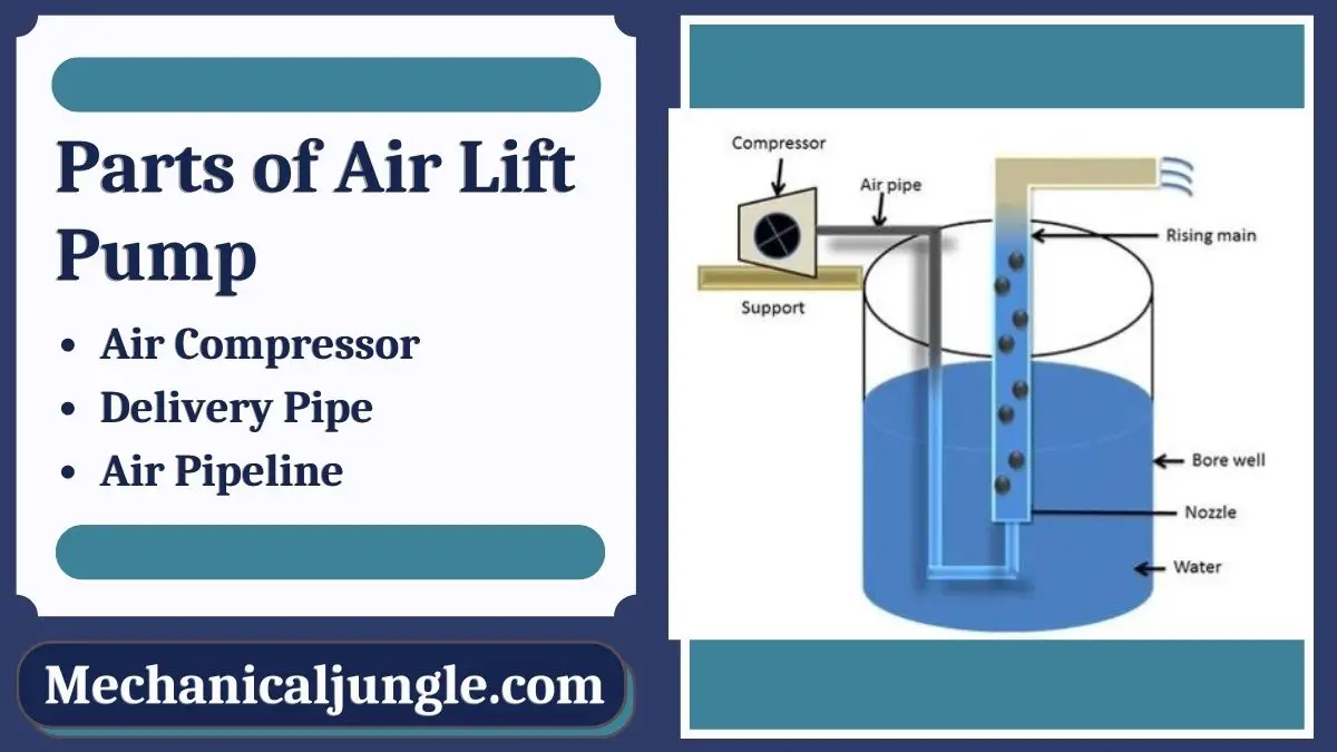
An air lift pumps are a device used to lift water from a well or a sump using compressed air. These pumps are also called mammoth pumps. Airlift pumps have been used since the early 20th century. The first airlift pump was invented in 1797 by German engineer Karl Emanuel Loscher. Air lift pumps are commonly found in agricultural land.
They are simple devices in which liquid enters from one end and a mixture of air and liquid discharge from the other end. Air is injected near the inlet. Almost without exceptions, the riser section of the airlift pumps has been a vertical pipe with a vertical cross-section.
Airlift pumps are typically used when maintenance needs to be kept to an absolute minimum. But this pump is not 100% maintenance-free because air is needed to deliver equipment to the pump that needs maintenance.
In air lift pumps, compressed air is mixed with water. We know that the density of water is much higher than the density of air. By buoyancy, the air that has a lower density than liquid rises quickly. By fluid pressure, the liquid is taken into the flow of the ascending air and moves in the same direction as the air.
The air is fed into the bottom of the riser pump, and this air freezes in water and form. As air mixes in water, the density of water decreases because the density of air and the mixture of water is less than the density of water.
So the mixture of air and water, also called froth, is much lower in density than water. Hence the main principle of air lift pump is the density difference between air and water mixture and water.
The velocity of the fluid through the pump and the velocity through the medium. The greater the difference between the respective velocities of fluid and air, the lower the overall efficiency of the pump.
For these pumps, the air injector system is in the form of an air jacket in which several holes are radially drilled through the pipe, and the air is supplied to them from the surrounding manifold.
An air pump is a device that uses the principles of gravity and inertia to move water by injecting a stream of compressed air into a pipe filled with a column of water.
An airlift pump is a pump that has low suction and moderate discharge of liquid and entrained solids. The pump injects compressed air into a pipe filled with a column of water.
The main advantage of the Husky double diaphragm air pump is that it can run dry for a limited time. A pump configuration in which the fluid source is located below the pump is called a pump stroke configuration. In other words, in a shock pump configuration, the pump draws from a fluid source located below the center line of the pump.
A major benefit of a Husky Air Operated Double Diaphragm pump is that it can run dry for a limited time. A pump layout in which the source of liquid is below the pump is called a suction lift configuration. In other words, in a suction lift configuration, a pump takes suction from a source of liquid located below the pump’s center line.
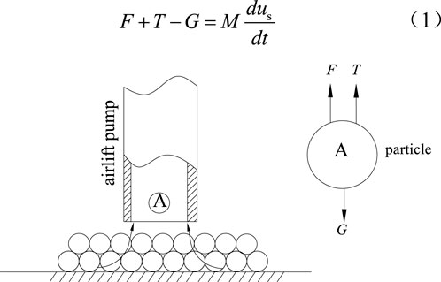
According to relevant research, it is clear that for a traditional mud pump, there will be blockage and wear during the dredging process because the flow cross-section of the blade is so large that its concentration is limited. Compressed air serves as the power source for air transportation, which can pump and transport liquid or mud through the combination of buoyancy, friction, and vacuum effects (Fu and Yan, 2004; Pei and Liao, 2010). To the best of our knowledge, the airlift system has many advantages, such as low cost, easy operation, simple configuration, no pollution to the environment, and less blockage (Chen et al., 2009; Pei and Tang, 2015). Therefore, it can be considered that the air transportation system has great potential for river and lake dredging.
Many scholars have carried out research, such as numerical simulation of the mixed fluid in the airlift system and analysis of the relationship between the injection parameter and the performance so that it has a higher matching, and thus, the performance of mud airlift is improved. Huang et al. (2017) performed a numerical simulation to study the effect of the nozzle type, injection depth, and injection hole diameter on the airlift pump, thereby improving the performance of the airlift pump. Alasadi and Habeeb (2017) then performed a numerical simulation study on the airlift pump with traditional and improved air injection devices under different intake flow rates, and the results show that the airlift pump with an improved air injection device can improve performance at higher intake flow rates. In actual operation, sufficient attention should be paid to the critical point of the solid particles carried in the bottom layer. If this is not given, it will cause blockage in the pump which will affect the performance and cause safety accidents in severe cases. When researchers study critical characteristics, they are mainly conducted from the perspective of experiments and rarely involve theoretical models. Taleb and Al-Jarrah (2017) performed an experiment to study the effect of the submergence ratio and air injection hole diameter on the performance of the airlift pump. The results showed that the performance of the airlift pump increased as the submergence ratio increased, while an injection hole diameter of 4 mm gave the highest performance. Oueslati A performed an experiment under many operating conditions, and proposed a theoretical model taking into account the air humidification and liquid temperature. The results showed that the proposed model is in good agreement with the experimental results. Fujimoto and Murakami studied the critical conditions of a mud airlift pump and obtained a model of the critical water flow rate for lifting solid particles at the bottom of the pump. By using this model, results that are consistent with reality can be obtained (Fujimoto et al., 2004). On this basis, our research team expanded the suction distance and obtained the rule of critical particle detonation. It needs to be clear that the aforementioned studies are only for water–solid two-phase flow (Tang et al., 2012). Fujimoto and Nagatani then used the aforementioned working conditions to analyze the critical conditions of particles transported in the three-phase flow. The research results show that in the three-phase flow, the starting of particles is easier, but the corresponding theoretical model is not proved (Fujimoto et al., 2005). In application, because of the constraint pressure (Pei et al., 2010; Hu et al., 2013), the particles are often compressed when they are deposited at the bottom, which makes it difficult to start the particles. At the same time, the airlift is caused to fail, but scholars rarely conduct research on this aspect.
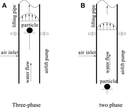
In this study, the research is carried out. The interface selects the inlet of the airlift pump to divide the mixed water into two fluid phases, one is a water–solid two-phase flow, and the other is a gas–water–solid three-phase flow. To satisfy the actual dredging, the medium used in this study is round river sand. Based on this, the critical conditions of the three-phase flow and two-phase flow are analyzed, and the relationship between the key condition and chip compaction is analyzed. For discussion, the research result of this study can provide a reference for other researchers to study related theories.
Analyzing Figure 3, it is clear that when JG,cri is increased, JL,3,cri will be reduced. After reaching the inflection point, JL,3,cri will decrease as JG,cri decreases. Therefore, by increasing JG,cri, the density of the mixed fluid can be reduced, so that the start of the particles becomes easier. Near the inflection point, because the gas value is large, the movement of the particles is mainly controlled by the water phase. From this, it can be clear that the performance of the airlift will be affected by working conditions, and it is necessary to reduce the air mass and then change the flow pattern in the tube, so that it can change from circular flow to elastic flow. It needs to be clear that this change is irreversible, that is, after reaching the inflection point, JL,3,cri will decrease with the decrease of JG,cri. According to the related research results (Hanafizadeh et al., 2011; Tang et al., 2016), the critical airlift of mud is opposite to the existence of the inflection point. In engineering applications, the inflection point needs to be moved down as much as possible. Comparing and analyzing the critical strength of particles with different diameters can be clear (Figure 3A). When the particle diameter is increased, JL,LS,cri and JL,3,cri will rise accordingly. The reason for this phenomenon is that increasing the particle diameter will increase the solid phase slip. In Figure 3B, it is clear that when the particle density increases, JL,LS,cri and JL,3,cri will rise accordingly. The reason for this phenomenon is that increasing the average density of the mixed water will reduce buoyancy. In addition, when increasing the particle density and diameter, the inflection point will move to the right (Kassab et al., 2007).
In the aforementioned model, particles need to be placed in the tube. However, in practical application, the particles will first deposit at the bottom of the water, and then they will be affected by the static chip retention effect. Obviously, the working conditions are different from those assumed by previous research. To be consistent with the practical situation, the research object selected in this study is particle B which is closest to the bottom of the pump. Figure 4 shows the force acting on particle B.
Compared with the critical water flow model[30] we constructed, it is clear that in this model, we only consider the static chip retention force (static chip retention effect) of the particles, which is in line with the actual engineering. Using the relevant parameters shown in Table 2 to calculate, the results of the model can be clarified (Figure 5). It is clear that with the increase of particle diameter dS and density ρS, the JL,LS,cri only shows a slight upward. On the contrary, when the immersion rate γ is continuously increased, JL,LS,cri will be significantly increased. If the particle density and size are smaller, then the immersion rate γ will control the start of the particle. Analyzing Figure 5, it can be clear that if the static chip retention effect is maintained, JL,LS,cri will be increased quickly. It is concluded that for small and medium particles, the airlift performance will be affected by the static chip retention effect.
It can be considered that in areas such as oceans and lakes, because of their greater depth, the particles have a larger static chip retention force, which causes the start to fail. If the particles are compacted, then it will prevent airlift dredging. Therefore, it is necessary to impact the sand layer before airlift, so that the static chip retention effect can be reduced.
Comparing the experimental results and the calculated results, it is clear (as shown in Figure 7) that the experimental value of the critical water flow rate for lifting the solid is lower than that of the calculation result when only lifting the particles. This situation occurs because the tube and the pump will coalesce, expand, rupture, and re-aggregate. The bubbles will move periodically, causing mixed fluid instability along the axial direction when it rises. Ascending, its oscillation characteristic is ascending-descending-ascending, and compared with descending motion, the ascending motion is more intense. According to the results of other researchers and ours, it can be inferred (Hu et al., 2012; Hu et al., 2015) that the basic feature of a slurry airlift is the oscillating upward motion of the mixed fluid, which will cause a transient vacuum, so there will be resistance. If the particle’s fluctuation reaches its peak, then the particle’s activation state can be advanced. Figure 7 also shows that if the immersion rate is lower, the mixed fluid will have more prominent oscillation characteristics, which will result in a higher instantaneous vacuum. To confirm these phenomena, high-speed cameras can be used.
Due to the effect of gravity, the particles will be affected by the static chip retention effect when they are deposited at the bottom of the water. When we are conducting research, we put sand particles on the bottom of the pump in advance (Figure 4). At this time, the sand will be closely arranged and in a double-stacked state. To maintain the static chip retention effect, the particles need to be placed in the water continuously for 7 days. Then we adjusted the water tank and preset the immersion rate. The particles in the center of the upper layer are the object, and the key experimental steps are repeated. Based on this, we can get JG, L, LS, Cri, JG, S, LS, Cri, and JL, LS, Cri. The research results show that the particles cannot start when the air compressor valve is adjusted from close to the maximum gas flow. Therefore, it can be considered that the static chip retention effect is obvious at the bottom. Even if the pump has a large water value and the resistance imposed on the particles is small, the static chip retention force cannot be overcome, thus making it impossible to carry out an airlift. To clarify the experimental results of JL,LS,Cri, we connected the outlet of the airlift pump to a high-power centrifugal pump. Table 4 shows the comparison results of theoretical and experimental critical values. Research on the table can be clear, and the calculation results show that the experimental results of JL,LS,Cri are low. Therefore, it can be considered that the fluctuation of water flow and surface defects between adjacent particles (Figure 4) will reduce the compactness, which finally weakens the static retention effect of the chips. Therefore, it can be considered that as long as the static chip retention effect exists, it will affect air transportation, so it is necessary to take measures to eliminate it.
2) In a water-solid two-phase flow, the physical properties of the water and particles will affect the critical water rate. However, in the gas–water–solid three-phase flow, not only will the physical properties of water and particles affect the critical water rate but so will the air rate. Before the inflection point, as the air critical flow increases, the water flow will decrease. After the inflection point, as the air critical flow increases, the water flow will increase. In addition, the existence of the inflection point is not conducive to airlift.
4) When there is a static chip retention effect under water, it is necessary to use auxiliary methods to impact the particle layer or to increase the resistance of the particles, otherwise, it will not be conducive to airlift.
Alasadi, A. A. M. H., and Habeeb, A. K. (2017). Experimental and numerical simulation of an airlift pump with conventional and modified air injection device. J. Eng. 23 (2), 62.
Fujimoto, H., Murakami, S., Omura, A., and Takuda, H. (2004). Effect of local pipe bends on pump performance of a small air-lift system in transporting solid particles. Int. J. Heat Fluid Flow 25 (6), 996–1005. doi:10.1016/j.ijheatfluidflow.2004.02.025
Fujimoto, H., Nagatani, T., and Takuda, H. (2005). Performance characteristics of a gas–liquid–solid airlift pump. Int. Jonalur Multiph. Flow 31 (10-11), 1116–1133. doi:10.1016/j.ijmultiphaseflow.2005.06.008
Hanafizadeh, P., Ghanbarzadeh, S., and Saidi, M. H. (2011). Visual technique for detection of gas–liquid two-phase flow regime in the airlift pump. J. Petroleum Sci. Eng. 75 (3-4), 327–335. doi:10.1016/j.petrol.2010.11.028
Hu, D., Kang, Y., Tang, C-L., and Wang, X-C. (2015). Modeling and analysis of airlift system operating in three-phase flow. China Ocean. Eng. 29 (1), 121–132. doi:10.1007/s13344-015-0009-z
Hu, D., Tang, C., Zhang, F., and Lin, Y. (2012). Theoretical model and experimental research of airlift device in borehole hydraulic jet mining[J]. J. China Coal Soc. 37 (3), 522. doi:10.13225/j.cnki.jccs.2012.03.014
Hu, D., Wu, X., Tang, C., and Liao, Z. (2013). Experimental study of airlift device for borehole hydraulic jet mining[J]. Mech. Sci. Technol. Aerosp. Eng. 32 (5), 756. doi:10.13433/j.cnki.1003-8728.2013.05.004
Kassab, S. Z., Kandil, H. A., Warda, H. A., and Ahmed, W. (2007). Experimental and analytical investigations of airlift pumps operating in three-phase flow. Chem. Eng. J. 131 (1–3), 273–281. doi:10.1016/j.cej.2006.12.009
Oueslati, A., and Megriche, A. (2017). The effect of liquid temperature on the performance of an airlift pump. Energy Procedia 119, 693–701. doi:10.1016/j.egypro.2017.07.096

We all have heard of air-lift pumps. These pumps are usually found near agricultural lands and irrigational fields where the availability of electricity is rare and intermittent. But have you ever wondered how air can lift water and pump it from deep wells? How intermittent availability of electricity does not interfere with the operation of these air-lift pumps? Let us discuss the operating principle, advantages and disadvantages of air-lift pumps.
An air-lift pump is a device which is used to lift water from a well or a sump with the use of compressed air. The compressed air is made to mix with the water. It is well known that the density of water is more than the density of air. So it is obvious and evident that air floats higher than water or to understand better, water has more weight than air. So the main principle used in air-lift pumps is the density difference between water and air. Air is made to mix with the water and thus allowed to form froth. Froth here consists of mixture of water and air. So the density of this mixture is less than that of the water. It is the mixture of air which makes the density less than water. Thus a very small column of pure water can balance a very long column of air-water mixture. This is the working principle of air-lift pumps.
These pumps do not require any electrical power from the power mains. Wondering how? There are systems installed in villages to irrigate agricultural fields. The system has a windmill which drives an air compressor. The compressed air from the air compressor is led into the pipe which has a nozzle in the deep wells. This system can also be modified by windmill driving a generator and power from this generator is used for compressing air and then used in these pumps.
Applications: These pumps, in spite of their poor efficiency, are commonly used in many areas where conventional pumps usage is difficult. These pumps are used in
Air-lift pumps are finding increasing use where pump reliability and low maintenance are required, where corrosive, abrasive, or radioactive fluids in nuclear applications must be handled and when a compressed air is readily available as a source of a renewable energy for water pumping applications. The objective of the present study is to evaluate the performance of a pump under predetermined operating conditions and to optimize the related parameters. For this purpose, an air-lift pump was designed and tested. Experiments were performed for nine submergence ratios, and three risers of different lengths with different air injection pressures. Moreover, the pump was tested under different two-phase flow patterns. A theoretical model is proposed in this study taking into account the flow patterns at the best efficiency range where the pump is operated. The present results showed that the pump capacity and efficiency are functions of the air mass flow rate, submergence ratio, and riser pipe length. The best efficiency range of the air-lift pumps operation was found to be in the slug and slug-churn flow regimes. The proposed model has been compared with experimental data and the most cited models available. The proposed model is in good agreement with experimental results and found to predict the liquid volumetric flux for different flow patterns including bubbly, slug and churn flow patterns
The air-lift pump has been used in various applications with its merit that it can pump up without any moving parts. E.g. coffee percolator, petroleum industry, suction dredge, OTEC i.e. ocean thermal energy conversion and so on. By the merit, it has high durability for high temperature water or vapor, and fluid-solid mixture like waste water, muddy water and crude, which cause problems when it"s pumped up with general pumps. In this regard, the air-lift pump has been one of the most desirable technology. A typical air-lift pump configuration is illustrated in Figure 01. The principle of this pump is very simple. When air is injected from the injector at bottom of a submerged tube, i.e., air bubbles are suspended in the liquid, the average density of the mixture in the tube is less than that of the surrounding fluid in the reservoir. Then hydrostatic pressure over the length of the tube is decreased. This buoyancy force causes a pumping action. The comparison of the simulated results, experimental result, and theoretical result is been able by data shown as Figure 04. They have similar trends but they also have a little differences because there are some limits of simulating the flow regimes. At the different flow condition, different coefficients for friction factor or pressure drop should be used, but this simulation uses a laminar condition and the theoretical equations are valid only for slug regime where the air flow rate is lower than the other regimes. From these causes, the differences has arisen, and difference comes bigger as the air flow rate increases, i.e., becoming annular flow regime or churn flow regime.
Results are presented of the specific performances of eight, different, water-pumping wind-turbines subjected to impartial tests at the Alberta Renewable Energy Test Site (ARETS), Alberta, Canada. The results presented which were derived from the test data, obtained independently of the equipment manufacturers, are expressed per unit of rotor projected area to eliminate the influence of machine size. Hub-height wind speeds and water flow rates for a common lift of 5.5 m (18 ft) constitute the essential test data. A general finding was that, to a first approximation, there were no major differences in specific performance between four units equipped with conventional reciprocating pumps two of which employed reduction gearing and two of which did not. It was found that a unit equipped with a Moyno pump performed well but three air-lift machines had, as was expected, poorer specific performances than the more conventional equipment. 10 refs., 9 figs.
Workplace monitoring, one of the key components of the radiation protection program is generally carried out by means of instruments installed permanently in respective areas or through portable air sampling instruments. Continuous air monitor (CAM) is one such monitor that constantly monitors the radionuclide concentration in air and triggers alarm as and when the air concentration goes above the pre-set levels. Conventional CAM system has a filter head, detector, display unit and a pump as four major parts. Pump may be either rotary vane or a vibrating diaphragm which are electrically driven using motors. Air lift pumps using ejectors are widely used where pump reliability and low maintenance are required, and where corrosive, abrasive, or radioactive fluids are handled. Since ejectors are uncomplicated alternative to vacuum pumps, an attempt was made to use the same as a pump for conventional CAMs. An ejector based sampling set up was made, tested and the results are represented in this paper
A study was undertaken to measure the efficiency with which carbon dioxide was stripped from freshwater (0‰) and saline water (35‰ NaCl) passing through an air-lift at 15 °C. The air-lift was constructed of 50 mm (OD) PVC pipe submerged 95 cm in a tank, had an adjustable air injection rate, and c...... for any water type (i.e. temperature, alkalinity, salinity and influent CO2 concentration).......A study was undertaken to measure the efficiency with which carbon dioxide was stripped from freshwater (0‰) and saline water (35‰ NaCl) passing through an air-lift at 15 °C. The air-lift was constructed of 50 mm (OD) PVC pipe submerged 95 cm in a tank, had an adjustable air injection rate......, and could be adjusted to three lifting heights: 11, 16 and 25 cm. The gas to liquid ratio (G:L) was high (1.9–2.0) at low water discharge rates (Qw) and represented the initial input energy required to raise the water up the vertical riser section to the discharge pipe. The air-lift increased in pumping...
Outlined herein are experimental results with a water hammer pump. It is a unique pump in that it depends only on potential energy of water to pump-up water. Water flows downwards from a reservoir at a high position into the pump , and is released from the exhaust valve. When velocity of water flowing in the pipe reaches a certain level, hydraulic force exceeds gravity of the exhaust valve to rapidly closes it, which is accompanied by rapid increase in pressure in the pump. High-pressure water flows into the air chamber, after pushing up the lifting valve, to compress air in the chamber. The lifting valve is closed, when pressure in the air chamber exceeds that in the pump, to pump up water in the chamber through the lifting pipe. Closure of the lifting valve produces a negative pressure within the pump, which, together with gravity of the exhaust valve, opens the valve again. The pump lifts water at 1.64l/min under the conditions of head: 3m and lift: 6m at an efficiency of 48.1%. 1 ref., 4 fig., 2 tab.
This invention relates to lifting appliances and particularly concerns a "pump and motor set" or motor-pump unit fitted with a lifting appliance enabling the motor to be separated from the pump. In nuclear power stations the reactor discharges heat that is carried by the coolant to a distant point away from the reactor to generate steam and electricity conventionally. In order to cause the reactor coolant to flow through the system, coolant motor-pump units are provided in the cooling system. These units are generally of the vertical type with an electric motor fitted vertically on the pump by means of a cylindrical or conical structure called motor support [fr
Due to the high costs to install electricity in remote locations, away from the regular urban electrical installations, photovoltaic solar energy has ample application in public illumination, water pumping, health services offices, etc. With the purpose to contribute to a better use of this kind of energy, this project aimed in analyzing the outflow and efficiency of a motor pump powered by photovoltaic panels, the irradiation necessary to activate it for water lift, collecting data at every 6- meter height, ranging from 6,2 to 18,2 meters. This study is part of a development project of the Universidade Tecnologica Federal do Parana (UTFPR), by making use of photovoltaic panels, motor pump, pyranometers, thermocouple type K, pressure transducer and outflow transducer. The data show a maximum average outflow of 584,299 Lh{sup -1} and maximum efficiency of 23,338% for a lift of 18,2 m. There is also the need of irradiation for the activation of the motor pump proportional to the height of the lift, in a polynomial dependence of the third order. (author)
In the Great Plains about 15 percent of the irrigation water pumped on farms comes from surface water sources; for the United States as a whole, the figure is about 22 percent. Because of forecast fuel shortages, there is a need to develop alternative energy sources such as wind power for surface water pumping. Specific objectives of this investigation were to: design and assemble a prototype wind powered pumping system for low lift irrigation pumping; determine performance of the prototype system; design and test an irrigation system using the wind powered prototype in a design and test an farm application; and determine the size combinations of wind turbines, tailwater pits, and temporary storage reservoirs needed for successful farm application of wind powered tailwater pumping systems in western Kansas. The power source selected was a two bladed, 6 m diameter, 9 m tall Darrieus vertical axis wind turbine with 0.10 solidity and 36.1 M(2) swept area.
The metering pump system that delivers high-level liquid wastes (HLLW) slurry to a melter is an integral subsystem of the vitrification process. The process of selecting a pump for this application began with a technical review of pumps typically used for slurry applications. The design and operating characteristics of numerous pumps were evaluated against established criteria. Two pumps, an air-displacement slurry (ADS) pump and an air-lift pump, were selected for further development. In the development activity, from FY 1983 to FY 1985, the two pumps were subjected to long-term tests using simulated melter feed slurries to evaluate the pumps" performances. Throughout this period, the designs of both pumps were modified to better adapt them for this application. Final reference designs were developed for both the air-displacement slurry pump and the air-lift pump. Successful operation of the final reference designs has demonstrated the feasibility of both pumps. A fully remote design of the ADS pump has been developed and is currently undergoing testing at the West Valley Demonstration Project. Five designs of the ADS pump were tested and evaluated. The initial four designs proved the operating concept of the ADS pump. Weaknesses in the ADS pump system were identified and eliminated in later designs. A full-scale air-lift pump was designed and tested as a final demonstration of the air-lift pump"s capabilities
This supporting document details calculations for the proper design of a lifting beam and redesigned lifting lugs for the 241AZO1A decant pump. This design is in accordance with Standard Architectural-Civil Design Criteria, Design Loads for Facilities (DOE-RL 1989) and is safety class three. The design and fabrication is in accordance with American Institute of Steel Construction, Manual of Steel Construction, (AISC, 1989) and the Hanford Hoisting and Rigging Manual (DOE-RL 1993)
Full Text Available The evolution of the major achievements in water lifting devices with emphasis on the major technologies over the centuries is presented and discussed. Valuable insights into ancient water lifting technologies with their apparent characteristics of durability, adaptability, and sustainability are provided. A comparison of the relevant technological developments in several early civilizations is carried out. These technologies are the underpinning of modern achievements in water engineering. They represent the best paradigm of probing the past and facing the future. A timeline of the historical development of water pumps worldwide through the last 5500 years of the history of mankind is presented. A chronological order is followed with emphasis on the major civilizations.
Personal air samplers are used to more conveniently obtain breathing zone samples from individuals over periods of several hours. Personal air sampling pumps must meet minimum performance levels under all working conditions to be suitable for use in radiation protection programs. In addition, the pumps should be simple to operate and as comfortable to wear as possible. Ten models of personal air sampling pumps were tested to evaluate their mechanical performance and physical characteristics. The pumps varied over a wide range in basic performance and operating features. Some of the pumps were found to have adequate performance for use in health physics air sampling applications. 3 references, 2 figures, 5 tables
Highlights: • The gas-lift pump has been adopted to enhance the natural circulation capability. • LENAC code is developed in my study. • The calculation results by LENAC code show good agreement with experiment results. • Gas mass flow rate, bubble diameter, rising pipe length are important parameters. -- Abstract: The gas-lift pump has been adopted to enhance the natural circulation capability in the type of lead–bismuth alloy cooled reactors such as Accelerator Driven System (ADS) and Liquid–metal Fast Reactor (LMFR). The natural circulation ability and the system safety are obviously influenced by the two phase flow characteristics of liquid metal–inert gas. In this study, LENAC (LEad bismuth alloy NAtural Circulation capability) code has been developed to evaluate the natural circulation capability of lead–bismuth cooled ADS with gas-lift pump. The drift flow theory, void fraction prediction model and friction pressure drop prediction model have been incorporated into LENAC code. The calculation results by LENAC code show good agreement with experiment results of CIRCulation Experiment (CIRCE) facility. The effects of the gas mass flow rate, void fraction, gas quality, bubble diameter and the rising pipe height or the potential difference between heat exchanger and reactor core on natural circulation capability of gas-lift pump have been analyzed. The results showed that in bubbly flow pattern, for a fixed value of gas mass flow rate, the natural circulation capability increased with the decrease of the bubble diameter. In the bubbly flow, slug flow, churn flow and annular flow pattern, with the gas mass flow rate increasing, the natural circulation capability initially increased and then declined. And the flow parameters influenced the thermal hydraulic characteristics of the reactor core significantly. The present work is helpful for revealing the law of enhancing the natural circulation capability by gas-lift pump, and providing theoretical
A bubble pump is proposed to replace the traditional mechanical solution pump in lithium bromide absorption chillers, for its advantageous feature that can be driven by industrial waste heat or solar energy or other low-grade energy. In two-stage bubble pump driven lithium bromide absorption refrigeration system, flow patterns in lifting pipe have significant effects on the performance of bubble pump. In this paper, the single bubble motion and the double bubbles coalescence in vertical ascending pipe are simulated by an improved free energy model of lattice Boltzmann method, in which the two-phase liquid to gas density ratio is 2778. The details of bubbles coalescence process are studied. Density and velocity of bubbles have been obtained. The computational results show that the initial radius of each bubble has a great influence on the coalescence time. The larger the initial bubble radius, the shorter the coalescence time. The pipe diameter has a little effect on the two bubbles coalescence time while it has a significant effect on the bubble velocity. As the pipe diameter increases, the bubble velocity increases. The obtained results are helpful for studying the transition mechanisms of two-phase flow patterns and useful for improving the bubble pump performance by controlling the flow patterns in lifting pipe.
This paper deals with individual air-to-air heat pumps in Danish dwellings and summerhouses and the question of to what extent they actually deliver savings of energy consumption. Results show that 20% of the expected reduction of electricity consumption is converted into increased comfort...... in the homes, including extended heating areas, keeping a higher temperature and a longer heating season and using the heat pump for air conditioning. Data include electricity consumption in 185 households before and after installation of heat pumps together with survey results of 480 households. Furthermore...... heating practices. These results have to be taken into account when making long-term energy planning for a sustainable energy system....
This study was carried out experimentally and analytically about the performance of solar cell panel system for operating the pump coupled by dc motor. The solar cell panel with total area 1.9848 m2 consists of three modules of 80 Wp each. The small centrifugal pump powered by dc motor is operated to lift water from 1m to 7m heads in sequence and gives the amount of water pumped over the whole day from 08.00 to 16.00 h are 11988, 10851, 8874, 7695, 5760, 3600...
This publication is a study of the dynamic performance of a 5-ton air-to-air heat pump in a residence in Washington, D.C. The effect of part-load operation on the heat pump"s cooling and heating coefficients of performance was determined. Discrepancies between measured performance and manufacturer-supplied performance data were found when the unit…
In this paper, we present a proton exchange membrane fuel cell (PEMFC) integrated with an electromagnetic (EM) air pump. The EM air pump provides the PEMFC with air by reciprocating motions of the permanent magnet attached to a flexible membrane. We performed a parametric study to decide the optimal dimensions of the reciprocating EM air pump. The effects of various operating parameters on the EM air pump were investigated with the root-mean-square (RMS) flow rate and current. A core with a higher relative permeability shows better performance. The RMS current linearly increases with the applied voltage and shows no dependence on the frequency. The RMS flow rate also increases with the voltage. The RMS flow rate per power consumption is highest at the frequency around 20 Hz and decreases as the applied voltage increases. When the reciprocating EM air pump was used to supply air to the portable PEMFC, it was found that the power density of the PEMFC increases with the applied voltage and shows the highest performance at the frequency of 10 Hz. We compared the performance of the PEMFC between the flow meter and the EM air pump used as an air supplier. About 81% of the output power using the flow meter was obtained when the EM air pump is operated at the applied voltage of 5 V. The parasitic power ratio reaches at its minimum value about 0.1 with an EM applied voltage of 0.25V. (paper)
This study was carried out experimentally and analytically about the performance of solar cell panel system for operating the pump coupled by dc-motor. The solar cell panel with total area 1.9848 m2 consists of three modules of 80 Wp each. The small centrifugal pump powered by dc-motor is operated to lift water from 1m to 7m heads in sequence and gives the amount of water pumped over the whole day from 08.00 to 16.00 h are 11988, 10851, 8874, 7695, 5760, 3600, 2340 L/d respectively. The hourl...
The ORNL Heat Pump Design Model is a FORTRAN-IV computer program to predict the steady-state performance of conventional, vapor compression, electrically-driven, air-to-air heat pumps in both heating and cooling modes. This model is intended to serve as an analytical design tool for use by heat pump manufacturers, consulting engineers, research institutions, and universities in studies directed toward the improvement of heat pump performance. The Heat Pump Design Model allows the user to specify: system operating conditions, compressor characteristics, refrigerant flow control devices, fin-and-tube heat exchanger parameters, fan and indoor duct characteristics, and any of ten refrigerants. The model will compute: system capacity and COP (or EER), compressor and


 8613371530291