
best mud pump parts free sample

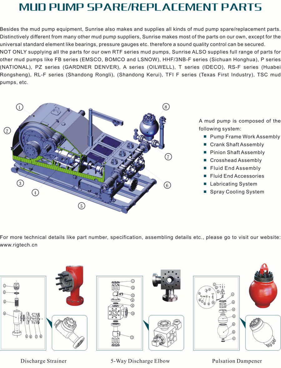
The 2,200-hp mud pump for offshore applications is a single-acting reciprocating triplex mud pump designed for high fluid flow rates, even at low operating speeds, and with a long stroke design. These features reduce the number of load reversals in critical components and increase the life of fluid end parts.
The pump’s critical components are strategically placed to make maintenance and inspection far easier and safer. The two-piece, quick-release piston rod lets you remove the piston without disturbing the liner, minimizing downtime when you’re replacing fluid parts.

Mud-Pump Gear Sets . . . . . . . . . . . . . . . . . . . . . . . . . . . . . . . . . . . . . . . . . . . . . . . . . . . . . . . . . . . . . . . . . 13

Adjust or replace these bearings at first sign of wear. The bearings in the crank end are babbitt lined steel shells, adjustable for wear by removing shims and easily replaced when completely worn. These bearings should be watched closely and adjusted at first signs of looseness.. You will note on series 3400, 3800, 3500, and 3900 pumps, that the shims do not completely fill the outer gap between rod and cap casting, although the connecting rod bolts are tight. This is because the faces of the shell bearings project slightly beyond the faces of the rod and cap castings, and the shims are gripped only between the faces of the bearing halves. Do not try to close this outer gap by tightening the connecting rod bolt as it will put an excessive strain on the bolts.
To check for wear, place a wrench on the top connecting rod bolt and shake the rod parallel to the crankshaft. (The pressure must be relieved from the liquid end of the pump, so that the pump"s mechanism is free to move.) If the rod bearing moves without resistance, the bearing may be too loose and need adjusting. If the bearing does need adjusting, remove shims until you cannot shake the rod, then add .005" shims one at a time until there is little side movement. Be sure to torque rod bolt nuts to proper value for each adjustment. Oil clearance should be checked with Plastigage (available in most parts stores). Wipe crankshaft journal clean of any oil, place a strip of Plastigage on the crankshaft journal and tighten rod cap to the proper torque value. Once tightened, remove rod cap and measure oil clearance with scale on Plastigage package. See oil clearance chart. (NOTE: If you are making this adjustment after having had the crossheads out, be sure that the oil holes in the rod are pointing up. The "up" side is indicated by matching numbers stamped on the cap and rod at the split between them. These numbers should be the same on each rod and should be on the top side of the crankshaft.) Rotate the shaft by hand and if there is any hard drag or tight spots in the bearing, add another 0.005" shim. After this bearing is properly adjusted, loosen bolts a few turns and repeat the above operation on the other bearings. After all bearings have been adjusted.
Torque all connecting rod bolt nuts back to proper value. Again rotate the pump by hand to check for excessive drag and tight spots. If none, the pump should be ready for operation.
If the pump cannot be rotated by hand due to the drive being enclosed, care must-be taken: not to over-tighten the bearings, since they cannot be checked by rotating the pump. When bearings are adjusted by this method, watch carefully for overheating when the pump is put into operation.
It is usually better to have a bearing a little too loose than too tight. A slightly loose bearing will cause very little trouble because of the slow operating speeds of the pump, but a tight bearing will overheat and the babbitt may melt or pull. Normal precautions must be taken to insure cleanliness of parts upon their assembly.
To check for wear, place a wrench on the top connecting rod bolt and shake the rod parallel to the crankshaft. (The pressure must be relieved from the liquid end of the pump so that the pump"s mechanism is free to move.) If the rod bearing moves without resistance, the bearing may be too loose and need adjusting. If the bearing does need adjusting, remove shims until you cannot shake the rod, then add .005" shims one at a time until there is a little side movement. Be sure to torque rod bolt nuts to proper value for each adjustment. (NOTE: If you are making this adjustment after having had the crossheads out, be sure that the oil holes in the rod are pointing up. The "up" side is indicated by matching numbers stamped on the cap and rod at the split between them. These numbers should be the same on each rod and should be on the top side of the crankshaft.) Turn the shaft by hand and if there is any hard drag or tight spots in the bearing, add another .005"" shim. After this bearing is properly adjusted, loosen bolts a few turns and repeat the above operation on the other bearings. After all bearings have been adjusted, torque all connecting rod bolt nuts back to proper amount. Again turn the pump by hand to check for excessive drag and tight spots. If none, the pump should then be ready for operation.
If the pump cannot be rotated by hand due to the drive being enclosed, the bearings may be completely adjusted by shaking the bearing on the shaft as stated above. Care must be taken not to over-tighten the bearings since they cannot be checked by rotating the pump by hand. When bearings are adjusted by this method, they must be watched carefully for overheating when the pump is put into operation.
Alternatively, plastic gauge strips, found in most parts stores may be used to adjust these bearings. It is usually better to have a bearing a little too loose than too tight. A slightly loose bearing will cause very little trouble because of the slow operating speeds of the pump, but a tight bearing will overheat and the babbitt may melt or pull. with experience, an operator can tell by feel when the bearings are properly adjusted. Normal precautions must be taken to insure cleanliness of parts upon their assembly. All wrenches used in adjusting these bearings are standard wrenches.
As usual, winter — or the slow season — is the time most drillers take the time to maintain their equipment in order to get ready for the peak season. One of the main parts that usually needs attention is the mud pump. Sometimes, it is just a set of swabs to bring it up to snuff, but often, tearing it down and inspecting the parts may reveal that other things need attention. For instance, liners. I can usually run three sets of swabs before it is time to change the liner. New liners and swabs last a good long time. The second set of swabs lasts less, and by the time you put in your third set of swabs, it’s time to order new liners. Probably rods too. It’s not always necessary to change pistons when you change swabs. Sometimes just the rubber needs to be changed, saving money. How do you tell? There is a small groove around the outside of the piston. As it wears, the groove will disappear and it’s time for a new piston.
The wear groove on a piston can be a good indicator of the general health of your pump. If the wear is pretty even all around, chances are the pump is in pretty good shape. But if you see wear on one side only, that is a clue to dig deeper. Uneven wear is a sign that the rods are not stroking at the exact angle that they were designed to, which is parallel to the liner. So, it’s time to look at the gear end. Or as some folks call it, “the expensive end.”
The wear groove on a piston can be a good indicator of the general health of your pump. If the wear is pretty even all around, chances are the pump is in pretty good shape. But if you see wear on one side only, that is a clue to dig deeper.
After you get the cover off the gear end, the first thing to look at will be the oil. It needs to be fairly clean, with no drill mud in it. Also look for metal. Some brass is to be expected, but if you put a magnet in the oil and come back later and it has more than a little metal on it, it gets more serious. The brass in the big end of the connecting rod is a wearable part. It is made to be replaced at intervals — usually years. The most common source of metal is from the bull and pinion gears. They transmit the power to the mud. If you look at the pinion gear closely, you will find that it wears faster than the bull gear. This is for two reasons. First, it is at the top of the pump and may not receive adequate lubrication. The second reason is wear. All the teeth on both the bull and pinion gears receive the same amount of wear, but the bull gear has many more teeth to spread the wear. That is why, with a well maintained pump, the bull gear will outlast the pinion gear three, four or even five times. Pinion gears aren’t too expensive and are fairly easy to change.
If the gears look OK and there are no obvious bearing problems, the next parts to look at are the crank journals; they ride in the brass at the big end of the rod and take plenty of abuse. This is where it gets interesting. To repair or replace is the big question. Replacement is pretty expensive and you may have to wait a while. Repairs are more my style because I know some excellent machinists and can tell them exactly what I need done. If your journals are deeply scored, you will have to turn the crank. It takes a pretty special machine to do this, but one of my friends has one and is a master with it. The procedure is to turn down the journals and press a steel sleeve over them, bringing them up to factory new specs.
This process is fairly straightforward machine work, but over the years, I have discovered a trick that will bring a rebuild up to “better than new.” When you tear a pump down, did you ever notice that there is about 1-inch of liner on each end that has no wear? This is because the swab never gets to it. If it has wear closer to one end than the other, your rods are out of adjustment. The trick is to offset grind the journals. I usually offset mine about ¼-inch. This gives me a ½-inch increase in the stroke without weakening the gear end. This turns a 5x6 pump into a 5½x6 pump. More fluid equals better holes. I adjust the rods to the right length to keep from running out the end of the liner, and enjoy the benefits.
Other than age, the problem I have seen with journal wear is improper lubrication. Smaller pumps rely on splash lubrication. This means that as the crank strokes, the rods pick up oil and it lubricates the crank journals. If your gear end is full of drill mud due to bad packing, it’s going to eat your pump. If the oil is clean, but still shows crank wear, you need to look at the oil you are using.
Oil that is too thick will not be very well picked up and won’t find its way into the oil holes in the brass to lubricate the journals. I’ve seen drillers that, when their pump starts knocking, they switch to a heavier weight oil. This actually makes the problem worse. In my experience, factory specified gear end oil is designed for warmer climates. As you move north, it needs to be lighter to do its job. Several drillers I know in the Northern Tier and Canada run 30 weight in their pumps. In Georgia, I run 40W90. Seems to work well.

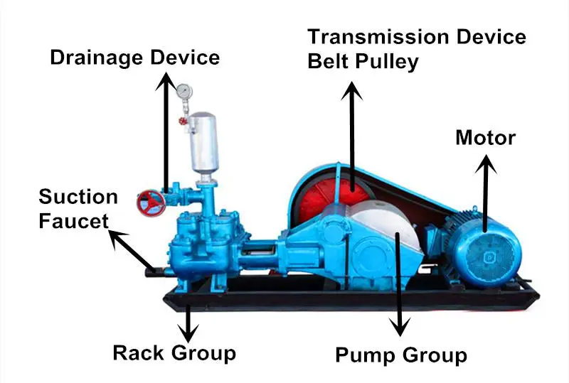
If you run a mud rig, you have probably figured out that the mud pump is the heart of the rig. Without it, drilling stops. Keeping your pump in good shape is key to productivity. There are some tricks I have learned over the years to keeping a pump running well.
First, you need a baseline to know how well your pump is doing. When it’s freshly rebuilt, it will be at the top efficiency. An easy way to establish this efficiency is to pump through an orifice at a known rate with a known fluid. When I rig up, I hook my water truck to my pump and pump through my mixing hopper at idle. My hopper has a ½-inch nozzle in it, so at idle I see about 80 psi on the pump when it’s fresh. Since I’m pumping clear water at a known rate, I do this on every job.
As time goes on and I drill more hole, and the pump wears, I start seeing a decrease in my initial pressure — 75, then 70, then 65, etc. This tells me I better order parts. Funny thing is, I don’t usually notice it when drilling. After all, I am running it a lot faster, and it’s hard to tell the difference in a few gallons a minute until it really goes south. This method has saved me quite a bit on parts over the years. When the swabs wear they start to leak. This bypass pushes mud around the swab, against the liners, greatly accelerating wear. By changing the swab at the first sign of bypass, I am able to get at least three sets of swabs before I have to change liners. This saves money.
Before I figured this out, I would sometimes have to run swabs to complete failure. (I was just a hand then, so it wasn’t my rig.) When I tore the pump down to put in swabs, lo-and-behold, the liners were cut so badly that they had to be changed too. That is false economy. Clean mud helps too. A desander will pay for itself in pump parts quicker than you think, and make a better hole to boot. Pump rods and packing last longer if they are washed and lubricated. In the oilfield, we use a petroleum-based lube, but that it not a good idea in the water well business. I generally use water and dish soap. Sometimes it tends to foam too much, so I add a few tablets of an over the counter, anti-gas product, like Di-Gel or Gas-Ex, to cut the foaming.
Maintenance on the gear end of your pump is important, too. Maintenance is WAY cheaper than repair. The first, and most important, thing is clean oil. On a duplex pump, there is a packing gland called an oil-stop on the gear end of the rod. This is often overlooked because the pump pumps just as well with a bad oil-stop. But as soon as the fluid end packing starts leaking, it pumps mud and abrasive sand into the gear end. This is a recipe for disaster. Eventually, all gear ends start knocking. The driller should notice this, and start planning. A lot of times, a driller will change the oil and go to a higher viscosity oil, thinking this will help cushion the knock. Wrong. Most smaller duplex pumps are splash lubricated. Thicker oil does not splash as well, and actually starves the bearings of lubrication and accelerates wear. I use 85W90 in my pumps. A thicker 90W140 weight wears them out a lot quicker. You can improve the “climbing” ability of the oil with an additive, like Lucas, if you want. That seems to help.
Outside the pump, but still an important part of the system, is the pop-off, or pressure relief valve. When you plug the bit, or your brother-in-law closes the discharge valve on a running pump, something has to give. Without a good, tested pop-off, the part that fails will be hard to fix, expensive and probably hurt somebody. Pop-off valve are easily overlooked. If you pump cement through your rig pump, it should be a standard part of the cleanup procedure. Remove the shear pin and wash through the valve. In the old days, these valves were made to use a common nail as the shear pin, but now nails come in so many grades that they are no longer a reliable tool. Rated shear pins are available for this. In no case should you ever run an Allen wrench! They are hardened steel and will hurt somebody or destroy your pump.
One last thing that helps pump maintenance is a good pulsation dampener. It should be close to the pump discharge, properly sized and drained after every job. Bet you never thought of that one. If your pump discharge goes straight to the standpipe, when you finish the job your standpipe is still full of fluid. Eventually the pulsation dampener will water-log and become useless. This is hard on the gear end of the pump. Open a valve that drains it at the end of every job. It’ll make your pump run smoother and longer.

FET manufactures a full range of valves and seats for every drilling and well-servicing application as part of our full line of Osprey® mud pump system solutions. All of our valves and seats can be used in water, water base, oil base and synthetic base mud applications. FET offers additional valves and seats not listed below, including drilling valves, frac valves and well service valves. FET’s QC standards for the dimensional and material specs are extremely rigid in comparison to other manufacturers. Contact your FET representative to learn more.
A wide variety of valve guide for mud pump parts options are available to you, such as 1 year, not available and 3 years.You can also choose from new, valve guide for mud pump parts,as well as from energy & mining, construction works , and machinery repair shops valve guide for mud pump parts, and whether valve guide for mud pump parts is 1.5 years, 6 months, or unavailable.

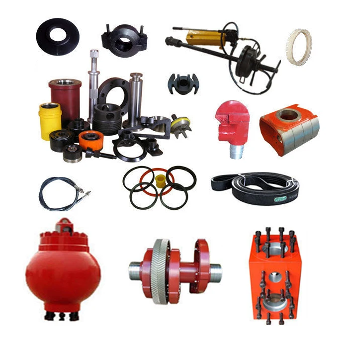
⊙Mud pump spare parts of abroad brand:Eg. Liner, piston, valve assembly, valve seat, valve spring, valve rubber could be alternative for original with lower price.
⊙Original brand:Emsco、Gardner-Denver, National oilwell, Ideco, Brewster, Drillmec, Wirth, Ellis, Williams, OPI, Mud King, LEWCO, Halliburton, SPM, Schlumberger, Weatherford.

This patent application incorporates by reference the patent application having attorney docket number 0301757-NP2, titled: DRYWALL MUD PUMP WITH CLAMP OR IMPROVED FOOT VALVE, having the same inventor and filed on the same date. These two patent applications have certain disclosure in common but were filed with different claims.
The joints between drywall sheets are typically filled and sealed with strips of paper or fiberglass mat and drywall joint compound, also called “joint compound”, “drywall mud”, or just “mud”. Joint compound may be made, for example, of water, limestone, expanded perlite, ethylene-vinyl acetate polymer and attapulgite. Joint compound may be applied as a viscous fluid that is thick enough to maintain its shape while it dries and hardens. In addition to forming joints, drywall mud is used to cover nail or screw heads, form a smooth or flat surface, and provide a texture over the surface. Paint or wall paper is typically applied over the drywall sheets and drywall joint compound.
Workers often specialize in the installation of drywall, and in large projects, different crews install the drywall panels (drywall hangers) from those who finish the joints and apply the joint compound (tapers or mud men). Workers who specialize in drywall installation often use specialized tools to increase their productivity. A number of tools have been invented and used for dispensing drywall joint compound. U.S. Pat. No. 7,473,085 (by Werner Schlecht), for example, describes a drywall finishing tool that is commonly referred to as a “flat box”, which is used to apply drywall joint compound between sheets of drywall, for instance. Further, drywall joint compound has been mixed at the job site in buckets, and various pumps have been used to pump the mud from the buckets into drywall tools such as flat boxes.
U.S. patent application Ser. No. 11/292,238, publication 2007/0122301 (also by Werner Schlecht) describes a drywall mud pump, for example. Various prior art drywall mud pumps used a piston in a main cylinder. In many cases, however, the piston did not travel the full length of the main cylinder. As a result, main cylinder sizes were made fairly large so that sufficient volume of drywall mud was pumped with each stroke of the pump. Further, in a number of designs, friction was excessive, making the pumps difficult to use, especially for large projects where workers have had to pump and apply a large quantity of drywall joint compound.
For these and other reasons, needs or potential for benefit exist for drywall mud pumps that are smaller in size, such as in diameter, that have less internal friction, that allow drywall mud to move freely therethrough, that have a longer piston stroke, or a combination thereof, as examples. In addition, in many prior art drywall pump designs, it was necessary to expend effort holding the pump in place while pumping drywall joint compound, which made using the pump more difficult. As a result, needs and potential for benefit exist for drywall mud pumps that do not need to be held in place while being used, as other examples. As further examples, drywall mud pumps are needed, or would be beneficial, that are inexpensive to manufacture, reliable, easy to use, that have a long life, that are easy to service and clean, and that are simple in operation so that typical operators can effectively maintain them, or that have a combination of such features. Room for improvement exists over the prior art in these and other areas that may be apparent to a person of ordinary skill in the art having studied this document. Other needs and potential for benefit may also be apparent to a person of skill in the art of specialized drywall tools.
Various embodiments provide, for example, as an object or benefit, that they partially or fully address or satisfy one or more of the needs, potential areas for benefit, or opportunities for improvement described herein, or known in the art, as examples. Some embodiments of the invention provide, among other things, various apparatuses, drywall mud pumps, and methods of selecting, obtaining, providing, manufacturing, or making such devices, as examples. Drywall mud pumps, for example, may be used to pump drywall joint compound from buckets into tools for dispensing the drywall joint compound, for instance, which may then be used to apply the drywall joint compound between and/or over sheets of drywall. Workers or operators may use such drywall mud pumps, for example, who specialize in the installation of drywall, or specifically, those who finish the joints and apply the joint compound (tapers or mud men), for instance. Various embodiments provide, for example, as an object or benefit, that they provide specialized drywall mud pumps, for instance, to increase the productivity of such workers.
A number of embodiments provide, for example, as objects or benefits, adaptations and improvements to drywall mud pumps in which a piston may travel a greater length of the main cylinder. As a result, in certain embodiments, main cylinder sizes may be smaller while still providing sufficient volume of drywall mud with each stroke of the pump. Further, in some embodiments, friction may be reduced, making the pumps less difficult to use, especially for large projects where workers may have to pump and apply a large quantity of drywall joint compound. Further, in some embodiments, drywall mud may move more freely through the pump, in comparison with certain prior art alternatives for instance. In addition, in some embodiments, it may require less effort to hold the pump in place while pumping drywall joint compound, which may make using the pump less difficult. In particular embodiments, drywall mud pumps may not need to be held in place by the operator while being used, for examples. Moreover, particular embodiments provide, as an object or benefit, for instance, drywall mud pumps that are inexpensive to manufacture, reliable, easy to use, that have a long life, that are easy to service and clean, and that are simple in operation so that typical operators can effectively maintain them.
Benefits of various embodiments of the invention exist over the prior art in these and other areas that may be apparent to a person of ordinary skill in the art having studied this document. These and other aspects of various embodiments of the present invention may be realized in whole or in part in various drywall mud pumps as shown, described, or both in the figures and related description herein. Other objects and benefits may also be apparent to a person of skill in the art of specialized drywall tools, for example.
In specific embodiments, this invention provides various drywall mud pumps for pumping drywall joint compound from a bucket into a drywall tool, for instance. In a number of these embodiments, such a drywall mud pump may include, for example, a main cylinder having a top end and an bottom end, a rod having a longitudinal axis, a first end, and a second end, and a piston which, when the drywall mud pump is assembled, is located within the main cylinder and is attached to the rod. In various embodiments, when the drywall mud pump is assembled, the second end of the rod is located within the main cylinder. Such embodiments may also include a pump head having an output aperture, and when the drywall mud pump is assembled, the pump head may be connected to the top end of the main cylinder and the rod may pass through the pump head, for example.
Various embodiments may further include a structural component, and when the drywall mud pump is assembled, the structural component may be rigidly attached to the main cylinder or to the pump head, for instance, and may extend from the main cylinder or the pump head to a pivot point, for example. Further, a number of such embodiments may include a handle which may include, for example, a first member and a second member. Further still, in various embodiments, when the drywall mud pump is assembled, the first member may be pivotably connected to the first end of the rod, the second member may be pivotably connected to the structural component at the pivot point, and the first member may slidably or telescopically engage the second member, for instance, to allow the rod to travel in a substantially straight line along the longitudinal axis while the second member rotates about the pivot point.
In particular such embodiments, when the drywall mud pump is assembled, the structural component is rigidly attached to the pump head and extends from the pump head to the pivot point. The structural component may be a separate piece from the pump head, for example. Further, some embodiments may include, for example, a bearing mounted within the second member, and when the drywall mud pump is assembled, part of the first member may fit inside the bearing and may extend into the second member.
Even further, some such embodiments may include a clamp, for example, configured to secure the drywall mud pump to a side of a bucket. In various embodiments, the clamp may include a force-amplification mechanism, for example, and a contact surface to contact the exterior of the bucket. In addition, in a number of embodiments, when the drywall mud pump is assembled and is installed within a bucket, the contact surface may face towards the main cylinder to secure the main cylinder within the bucket by compressing the side of the bucket between the contact surface and the main cylinder, for instance.
Furthermore, particular embodiments may include, for example, a foot valve, which, when the drywall mud pump is assembled, may be attached to the bottom end of the main cylinder allowing drywall joint compound to flow into the main cylinder through the foot valve, but substantially preventing drywall joint compound from flowing out of the main cylinder through the bottom end of the main cylinder. In certain embodiments, the foot valve may include, for example, a pin and two semi-circular-shaped rigid flaps that hingedly rotate about the pin.
In other embodiments, the invention also provides various drywall mud pumps that include, for example, such a main cylinder, such a rod, and such a piston. In these embodiments, the piston may include, for example, at least one orifice through the piston to pass drywall joint compound when the piston is traveling downward in the main cylinder. In various embodiments, the piston may further include at least one flapper to block the at least one orifice to substantially prevent passage of drywall joint compound through the piston when the piston is traveling upward in the main cylinder. Such embodiments may further include a pump head, such as described above, and the pump head may include, for example, a seal around the rod.
These embodiments may further include a structural component, and when the drywall mud pump is assembled, the structural component may be attached in rigid relation to the main cylinder or to the pump head and may extend to a pivot point in rigid relation to the main cylinder. Even further, these embodiments may include a handle that may include, for example, a first member, a second member, and a bearing which may include, for instance, multiple balls or PTFE. In various embodiments, when the drywall mud pump is assembled, the first member may be pivotably connected to the first end of the rod, the second member may be pivotably connected to the structural component at the pivot point, and the first member may slidably engage the second member through the bearing, for example.
Such embodiments may have other features previously mentioned for other embodiments as well. For example, in some embodiments, the first member slidably engages the second member, part of the first member may fit inside the second member, the drywall mud pump may include a foot valve (e.g., as described above), or a combination thereof. Furthermore, in some embodiments, the drywall mud pump may include, for example, a clamp configured to secure the drywall mud pump to a side of a bucket, which may be a toggle clamp, for instance.
The invention also provides various methods, for example, of selecting, obtaining, or providing a drywall mud pump for pumping drywall joint compound from a bucket into a drywall tool. Such methods may include, for example, various acts, which may be performed in any order or in the order listed, as examples. In some such methods, these acts may include, for instance, selecting, obtaining, or providing a body that may include, for example, an inlet to take in drywall joint compound from the bucket, and an output aperture to deliver drywall joint compound to the drywall tool. Various such methods may further include acts of selecting, obtaining, or providing a driver to move the drywall joint compound through the body, and selecting, obtaining, or providing a structural component which, when the drywall mud pump is assembled, may be attached to the body and may extend to a pivot point. Such methods may also include, for further example, an act of selecting, obtaining, or providing a handle that may include, for example, a first member and a second member. In various embodiments, when the drywall mud pump is assembled, the first member may be connected in driving relation to the driver, the second member may be pivotably connected to the structural component at the pivot point, and the first member may slidably or telescopically (or both) engage the second member while the second member rotates about the pivot point, for instance.
In some embodiments, such methods may further include, for example, an act of selecting, obtaining, or providing a bearing, such as a PTFE bearing, for example, which, when the drywall mud pump is assembled, is mounted within the second member. Further, in various embodiments, when the drywall mud pump is assembled, part of the first member fits inside the bearing and extends into the second member. Moreover, particular embodiments may include, for example, an act of selecting, obtaining, or providing a clamp (e.g., as described above) configured to secure the drywall mud pump to a side of a bucket. Furthermore, some embodiments may further include, for example, an act of selecting, obtaining, or providing an inlet valve, which, when the drywall mud pump is assembled, is attached to the inlet of the body, allowing drywall joint compound to flow into the body through the inlet valve, but substantially preventing drywall joint compound from flowing out of the body through the inlet. In certain embodiments, the inlet valve may include, for example, a pin and two semi-circular-shaped rigid flaps that hingedly rotate about the pin.
In various embodiments the act of selecting, obtaining, or providing the driver may further include selecting, obtaining, or providing a piston having at least one orifice therethrough to pass drywall joint compound through the piston, and having at least one flapper to block the at least one orifice to prevent passage of drywall joint compound through the piston. Further, in some embodiments, the act of selecting, obtaining, or providing the body may include selecting, obtaining, or providing a main cylinder, and in particular embodiments, such methods may further include, for example, an act of selecting, obtaining, or providing a rod which, when the drywall mud pump is assembled, extends from the first member to the driver. Still further, in some embodiments, when the drywall mud pump is assembled, the structural component may be attached in rigid relation to the body and the pivot point may be in rigid relation to the body.
FIG. 7 is a cross sectional front view of another embodiment of a drywall mud pump, this embodiment having a toggle clamp and shown clamped inside a bucket;
FIG. 11 is a partial cross sectional view of a the handle of the drywall mud pump shown in FIGS. 7 and 8 with the grip and the pivot clamp omitted, showing, among other things, the other parts of the second member including the bearing;
FIG. 14 is a side view of the toggle clamp of FIG. 13, showing, among other things, the positions of the parts the clamp when the clamp is fully closed (clamped) and fully open (unclamped);
FIG. 16 is an isometric view of the flappers and tube of an inlet valve or foot valve which may be part of the drywall mud pump shown in FIGS. 7 and 8, or other embodiments described herein, for example;
FIG. 27 is a flow chart illustrating, among other things, an example of a method of selecting, obtaining, or providing a drywall mud pump, for example, for pumping drywall joint compound from a bucket into a drywall tool.
Among other things, various embodiments are, include, obtain, or provide various drywall mud pumps, for example, for pumping drywall joint compound from a bucket into a drywall tool. FIGS. 1-4 illustrate a first embodiment 10 of a drywall mud pump, FIGS. 5 and 6 illustrate a second embodiment 50 of a drywall mud pump, and FIGS. 7 and 8 illustrate a third embodiment 70 of a drywall mud pump, as examples. These figures illustrate assembled drywall mud pumps. Such pumps may be sold, shipped, or stored partially or fully disassembled, however. In a number of embodiments, a drywall mud pump may include, for example, a body, which may be or include a main cylinder (e.g., 11, 51, or 71) having (e.g., in the position shown of normal operation) a top end (e.g., 111, 511, or 711) and an bottom end (e.g., 112, 512, or 712), a rod (e.g., 12, 52, or 72) having a longitudinal axis, a first end (e.g., 121, 521, or 721), and a second end (e.g., 122 or 722), and a piston (e.g., 33 or 73 shown in FIGS. 3, 4, and 7). In a number of embodiments, when the drywall mud pump (e.g., 10, 50, or 70) is assembled, the piston (e.g., 33 or 73) may be located within the main cylinder (e.g., 11, 51, or 71) and may be attached to the rod (e.g., 12, 52, or 72). Pistons 33 and 73 are examples of drivers to move drywall joint compound through the body of drywall mud pumps 10 and 70.
In various embodiments, when the drywall mud pump (e.g., 10, 50, or 70) is assembled, the second end (e.g., 122 or 722) of the rod (e.g., 12, 52, or 72) is located within the main cylinder (e.g., 11, 51, or 71), for instance, attached to the piston (e.g., 33 or 73). Such embodiments may also include a pump head (e.g., 14, 54, or 74), for instance, which may be part of the body, having an output aperture (e.g., 144, 544, 744), and when the drywall mud pump (e.g., 10, 50, or 70) is assembled, the pump head (e.g., 14, 54, or 74) may be connected to the top end (e.g., 111, 511, or 711) of the main cylinder (e.g., 11, 51, or 71), for example, with fasteners, screws, bolts, clips, pins, or the like, as examples (e.g., clips 117 are shown for this purpose in FIGS. 1-6). In a number of embodiments, the rod (e.g., 12, 52, or 72) may pass through the pump head (e.g., 14, 54, or 74), for example. In a number of embodiments, the pump head (e.g., 14, 54, or 74) may include a seal around the rod (e.g., 12, 52, or 72), for example, an elastomeric o-ring or a u-cup, which may substantially prevent drywall joint compound from leaking out of the pump around the rod when the pump is used.
Various embodiments may further include a handle (e.g., 17, 57, or 77 shown in FIGS. 1 to 8) and a bracket or structural component (e.g., 15, 55, or 75) to support the handle of the pump. In a number of embodiments, when the drywall mud pump (e.g., 10, 50, or 70) is assembled, the structural component (e.g., 15, 55, or 75) may be rigidly attached to the main cylinder (e.g., 11, 51, or 71) or to the pump head (e.g., 14, 54, or 74), for instance, and may extend from the main cylinder (e.g., 11, 51, or 71) or the pump head (e.g., 14, 54, or 74) to a pivot point (e.g., 16, 56, or 76), for example. FIG. 9 further illustrates structural component 75 (introduced in FIG. 7) having pivot point 76 at one end and pins or fasteners 99 at the other end to attach structural component 75 to pump head 74, for example.
In various embodiments, the structural component (e.g., 15, 55, or 75) may be attached in rigid relation to the main cylinder (e.g., 11, 51, or 71) or to the pump head (e.g., 14, 54, or 74) (or both) and may extend to a pivot point (e.g., 16, 56, or 76) in rigid relation to the main cylinder (e.g., 11, 51, or 71), for example. In different embodiments, this may be accomplished by attaching the structural component (e.g., 15, 55, or 75) directly to the main cylinder (e.g., 11, 51, or 71) or to the pump head (e.g., 14, 54, or 74), or may be accomplished by attaching the structural component (e.g., 15, 55, or 75) to one or more other components that may be attached to the main cylinder (e.g., 11, 51, or 71) or to the pump head (e.g., 14, 54, or 74), or both, as examples.
As used herein, in this context, two parts being in “rigid relation” means that the parts do not move (e.g., translate or rotate) significantly relative to each other (other than due to insignificant elastic deformation of the material) while the drywall mud pump is in operation. Further, as used herein, two parts being rigidly attached to each other means that the parts are in “rigid relation”. Being “rigidly attached” or in “rigid relation” does not exclude the possibility that the two parts are detachable, for example, for disassembly, cleaning, shipping, or storage of the drywall mud pump, as examples. In fact, in many embodiments, the structural component (e.g., 15, 55, or 75) may be detachable from the pump head (e.g., 14, 54, or 74), cylinder (e.g., 11. 51, or 71), or both, for example.
In a number of embodiments, the handle (e.g., 17, 57, or 77 shown in FIGS. 1 to 8) may include, for example, a first member (e.g., 171, 571, or 771) and a second member (e.g., 172, 572, or 772). Further still, in various embodiments, when the drywall mud pump (e.g., 10, 50, or 70) is assembled, the first member (e.g., 171, 571, or 771) may be pivotably connected to the first end (e.g., 121, 521, or 721) of the rod (e.g., 12, 52, or 72), the second member (e.g., 172, 572, or 772) may be pivotably connected to the structural component (e.g., 15, 55, or 75), for instance, at the pivot point (e.g., 16, 56, or 76), or both, as examples.
Various such embodiments include a handle (e.g., 17, 57, or 77) which, when the drywall mud pump (e.g., 10, 50, or 70) is assembled, may be pivotably connected to the first end (e.g., 121, 521, or 721) of the rod (e.g., 12, 52, or 72), and may be pivotably connected to the structural component (e.g., 15, 55, or 75) at the pivot point (e.g., 16, 56, or 76). Some such handles may include the first member (e.g., 171, 571, or 771) and the second member (e.g., 172, 572, or 772) previously mentioned. FIG. 10 further illustrates first member 771 (e.g., of handle 77) introduced in FIG. 7. In the embodiments illustrated in FIGS. 1-4 and 7-8, for example, the first member (e.g., 171 or 771 of handle 17 or 77) is connected in driving relation (e.g., via rod 12 or 72) to the piston (e.g., 33 or 73), which are examples of drivers.
In the embodiment illustrated, when the drywall mud pump (e.g., 10 or 70) is assembled, part of the first member (e.g., 171 or 771) may fit inside the bearing (e.g., 37 or 737) and may extend into the second member (e.g., 172, 572, or 772). In a number of embodiments, the bearing (e.g., 37 or 737) may be a linear ball bearing, for example, and may include a sleeve-like outer ring and several rows of balls retained by cages. The cages or ball tracks may be oriented to provide for low friction rolling motion in a linear direction (e.g., in the axial direction). The cages or ball tracks may then curve around to return the balls to be used again. The return cages or ball tracks, and the portions of the cages and ball tracks that curve, may be deeper to prevent the balls from contacting the moving surface (e.g., first member 171, 571, or 771) when the balls are traveling in a different direction.
In various embodiments, when the drywall mud pump (e.g., 10, 50, or 70) is assembled, the first member (e.g., 171, 571, or 771) may be pivotably connected to the first end (e.g., 121, 521, or 721) of the rod (e.g., 12, 52, or 72), the second member (e.g., 172, 572, or 772) may be pivotably connected to the structural component (e.g., 15, 55, or 75) at the pivot point (e.g., 16, 56, or 76), and the first member (e.g., 171, 571, or 771) may slidably engage the second member (e.g., 172, 572, or 772) through the bearing (e.g., 37 or 737), for example. Such pivotable connections may include a pin or a fastener, such as a screw or a bolt, as examples.
As shown in FIG. 7, handle 77 also includes grip 773 which may be made of an elastomeric material and may be attached to elongated member 113, second member 772, or handle 77, for example, with an adhesive. As further illustrated in FIG. 7, and shown in detail in FIG. 12, handle 77 and second member 772 thereof also includes pivot clamp 775 which extends from elongated member 113, to pivot point 76. Pivot point 76 may include a pin or fastener (e.g., a screw or bolt) that handle 77 may rotate about when pump 70 is in use. A separate fastener may pass through hole 125 in pivot clamp 775 to tighten pivot clamp 775 around elongated member 113 to secure pivot clamp 775 in place on handle 77.
In the illustrated embodiments, when the drywall mud pump (e.g., 10, 50, or 70) is assembled, the structural component (e.g., 15, 55, or 75) is rigidly attached to the pump head (e.g., 14, 54, or 74) and extends from the pump head (e.g., 14, 54, or 74) to the pivot point (e.g., 16, 56, or 76). The structural component (e.g., 15, 55, or 75) may be a separate piece from the pump head (e.g., 14, 54, or 74), for example, as shown, and may be attached thereto with fasteners, such as screws or bolts, for instance (e.g., pins or fasters 99 shown in FIG. 9). In other embodiments, a structural component (e.g., in lieu of 15, 55, or 75) may pivotably attach to the pump head, as another example. In the embodiments illustrated, structural members 15, 55, and 75 are formed from flat plate, for example. Other embodiments may have a different shape, such as having an I-beam cross section, being tubular (e.g., round, square, rectangular, or oval), or being an angle beam or a channel, as examples. Structural member 55 shown in FIGS. 5 and 6 illustrates that one or more cut outs or holes may be formed in structural members, for instance, to reduce the amount of material, reduce weight, provide attachment points, or the like, as examples. In some embodiments, a structural member (e.g., corresponding to 15, 55, or 75) may be a truss or may consist of two, three, four, or more sub-members, as other examples.
FIGS. 1, 3, and 7 illustrate that a number of embodiments may also include a clamp (e.g., 18 or 78), which may be configured to secure (e.g., by clamping) the drywall mud pump (e.g., 10 or 70) to a side of the bucket (e.g., 80 shown in FIGS. 7 and 8). Bucket 80 may be a common five-gallon plastic bucket, for example. In various embodiments, the clamp (e.g., 18 or 78) may include a force-amplification mechanism (e.g., 181 or 781), for example, and a contact surface (e.g., 182 or 782), for instance, to contact the exterior of the bucket (e.g., 80). In the embodiments shown, when the drywall mud pump (e.g., 10 or 70) is assembled and is installed within a bucket (e.g., 80), the contact surface (e.g., 182 or 782) may face towards the main cylinder (e.g., 11 or 71) to secure the main cylinder (e.g., 11 or 71) within the bucket (e.g., 80), for example, by compressing the side of the bucket (e.g., 80) between the contact surface (e.g., 182 or 782) and the main cylinder (e.g., 11 or 71), for instance.
FIGS. 1 and 3 illustrate that in some embodiments, the drywall mud pump (e.g., 10) further includes a clamp bracket (e.g., 19) which, when the drywall mud pump (e.g., 10) is assembled, may extend from the pump head (e.g., 14) to the clamp (e.g., 18). In embodiment 10 of the drywall mud pump, clamp bracket 19 rigidly attaches to pump head 14, and clamp 18 attaches to clamp bracket 19. In other embodiments, the clamp (e.g., 78 shown in FIG. 7) may attach directly to the pump head (e.g., 74), or the clamp (e.g., 78) may attach directly to a ring that may attach to the pump head (e.g., 74) or to the main cylinder (e.g., 71), as examples. In some embodiments, a clamp may attach directly or indirectly to the main cylinder (e.g., 11, 51, or 71). In various embodiments, the clamp may be attached such that at least part of the clamp is in rigid relation to the main cylinder, the pump head, or both, for example.
In the embodiment shown in FIGS. 1-4, clamp 18 includes an arc-shaped jaw 185 having concave surface 182 to contact the exterior of the bucket. In this embodiment, when drywall mud pump 10 is assembled, concave surface 182 faces away from force-amplification mechanism 181 and concave surface 182 faces towards main cylinder 11 for clamping main cylinder 11 within the bucket. In this embodiment, claim 18 is a screw-type clamp, and force-amplification mechanism 181 is a threaded screw mechanism that is operated by rotating handle 183. Other embodiments of force-amplification mechanisms (e.g., 781) may use leavers, cams, or the like, as other examples.
As illustrated in FIGS. 5 and 6, in some embodiments, the drywall mud pump (e.g., 50) may include a foot plate (e.g., 59) which, when the drywall mud pump (e.g., 50) is assembled, may be attached to the pump head (e.g., 54) and may extend, for example, parallel to the main cylinder (e.g., 51), for instance, at least as far (e.g., downward) from the pump head (e.g., 54) as the bottom end (e.g., 512) of the main cylinder (e.g., 51) or from the bottom of the drywall mud pump (e.g., 50). In this embodiment, rather than clamping to a bucket, the operator steps on lower portion 592 of foot plate 59 while pumping to stabilize drywall mud pump 50. Certain embodiments may have a clamp and a foot plate, as another example.
Furthermore, particular embodiments may include, for example, an inlet valve or a foot valve (e.g., 42 or 742 shown in FIGS. 1 to 4 and 7 to 8), which, when the drywall mud pump (e.g., 10, 50, or 70) is assembled, may be attached to the bottom end (e.g., 112, 512, 712) of the main cylinder (e.g., 11, 51, or 71). The bottom end (e.g., 112, 512, 712) of the main cylinder (e.g., 11, 51, or 71) or the foot valve (e.g., 42 or 742), as examples, may be, or form, an inlet to take in drywall joint compound, for example, from bucket 80. A foot valve (e.g., 42 or 742) may allow drywall joint compound to flow into the main cylinder (e.g., 11, 51, or 71), for instance, from the bucket (e.g., 80) through the foot valve (e.g., 42 or 742), but may substantially prevent drywall joint compound from flowing out of the main cylinder (e.g., 11, 51, or 71) through the bottom end (e.g., 112, 512, 712) of the main cylinder (e.g., 11, 51, or 71).
Foot valve 42 and foot valve 742 are examples of inlet valves, which, when the drywall mud pump (e.g., 10, 50, or 70) is assembled, are (one such valve is) attached to the inlet of the body (e.g., main cylinder 11, 51, or 71) allowing drywall joint compound to flow into the inlet and into the body through the inlet valve, but substantially preventing drywall joint compound from flowing out of the body through the inlet. As used herein, a foot valve (e.g., 42 or 742) “substantially” prevents drywall joint compound from flowing out of the body or main cylinder (e.g., 11, 51, or 71), for instance, through the inlet or bottom end (e.g., 112, 512, 712) if, when the drywall mud pump is in use, the amount of drywall joint compound that passes up through the inlet valve or foot valve during an upward stroke of the piston, for example, is at least twice the amount of drywall joint compound that passes downward through the foot valve during a downward stroke of the piston. Considerably better performance may be accomplished, however, in many embodiments.
In certain embodiments, the foot valve (e.g., 42 or 742) may include, for example, a pin (e.g., 32 shown in FIGS. 1-8). In some embodiments, such a pin may have a ring at a first end, a spring detent at a second end, or both (e.g., on opposite ends), as examples. In some embodiments, two semi-circular-shaped rigid flaps may hingedly rotate about the pin (e.g., 32). FIGS. 16-19 illustrate an example of such an embodiment. In this embodiment, semi-circular-shaped rigid flaps 161 and 162 hingedly rotate about tube 163, for example, as the foot valve (e.g., 42 or 742) opens and closes. In other embodiments, corresponding flaps may have a different shape, such as rectangular. In the particular embodiment shown, the pin (e.g., 32) fits inside tube 163 and secures flaps 161 and 162 and tube 163 within the bottom end (e.g., 112, 512, or 712) of the main cylinder (e.g., 11, 51, or 71). In a number of embodiments, the pin (e.g., 32), tube (e.g., 163), or both, may extend through a portion of each of the flaps. In the specific embodiment illustrated, for example, at least when the drywall mud pump (e.g., 10, 50, or 70) is assembled, tube 163 extends through portions 164, 165, 166, 167, and 168 of flaps 161 and 162. Other embodiments may omit tube 163 or may omit the pin (e.g., 32) (or the tube may be the pin) and the tube may perform some or all of the function that the pin performs in the embodiment shown.
As shown in FIGS. 1 and 2, in the embodiment illustrated, pin 32 also attaches base 421 of foot valve 42 (e.g., to cylinder 11). FIG. 20 further illustrates base 421. Base 421 includes feet 422 which may provide space between bottom end 112 of main cylinder 11 and the bottom of the bucket (e.g., 80), for example, so that drywall joint compound can flow relatively freely into foot valve 42. Further feet 422 may partially or fully support drywall mud pump 10 against the bottom of the bucket. As shown in FIG. 20, base 421 includes holes 205 that pin 32 passes through to secure base 421 and foot valve 42 to bottom end 112 of main cylinder 11. Holes 205 may be large enough in diameter to pass pin 32, but too small to pass tube 163, for example.
In the embodiment illustrated, screw 423 shown in FIGS. 1-3 may act as a stop for flaps 161 and 162 preventing the flaps from raising or opening too far. This assures, in this particular embodiment, that flaps 161 and 162 close (i.e., lower) quickly and reliably when piston 33 starts its downward stroke. In many embodiments, foot valve 42 may further include a screen, for example, below flaps 161 and 162, that may serve to prevent debris and solid chunks of drywall joint compound from being drawn into drywall mud pump 10. Such a screen may be retained by or attached to base 421 of foot valve 42, in some embodiments, for example. Foot valve 742 shown in FIG. 7 may be similar to foot valve 42. In some embodiments, drywall mud pump 50 shown in FIGS. 5 and 6 may have a similar foot valve.
FIG. 8 illustrates that various embodiments may include a high filler (e.g., 88), a goose neck (e.g., 89), or both. Although both high filler 88 and goose neck 89 are shown in FIG. 8, only one of high filler 88 or goose neck 89 would be installed on drywall mud pump 70 at a time, in this embodiment. FIGS. 25 and 26 further illustrate high filler 88 and goose neck 89. In the embodiment illustrated, high filler 88 and goose neck 89 are each formed from a piece of tubing having a round cross section and configured at the ends of the tubing to releasably attach to pump head 74 and to a drywall tool. Where high filler 88 and goose neck 89 attach to a drywall dispensing tool, for example, high filler 88 and goose neck 89 may include a bushing, a seal such as an o-ring, or both, as examples. In the embodiment shown, high filler 88 may be used to fill a flat box, for example, without requiring the operator to bend over as far. Further, in this embodiment, goose neck 89 may be used to fill a corner tool that has a cylinder that holds drywall joint compound under pressure from a piston and spring (e.g., a pneumatic spring) for example. In some embodiments, a high filler may discharge over the bucket (e.g., 88) to avoid spills (e.g., so that spills from the high filler fall back into the bucket).
In the embodiment illustrated, high filler 88 and goose neck 89 attach (e.g., one at a time) to output aperture 744 of pump head 74. Output aperture 744, or the end of high filler 88 or goose neck 89 that attaches to the drywall dispensing tool, are examples of outlet apertures to deliver drywall joint compound to the drywall tool. Outlet apertures 144 and 544 are other such examples. In the embodiment illustrated, high filler 88 and goose neck 89 each have two bends. Specifically, high filler 88 has two 90 degree bends, and goose neck 89 has one 90 degree bend and one 180 degree bends. Other embodiments may differ.
FIGS. 5 and 6 illustrate handle 57 in a fully raised and fully lowered position for embodiment 50 of the drywall mud pump. In various embodiments, for example, the handle may rotate between 80 and 120 degrees, or between 90 and 110 degrees, from the fully raised to the fully lowered position, as examples. In specific embodiments, for example, the handle may rotate about 100 degrees from the fully raised to the fully lowered position. As used herein, “about”, when referring to angles of handle rotation, means within plus or minus 5 degrees. In other embodiments, for further example, the handle may rotate about 50, 60, 70, 80, 85, 90, 95, 105, 110, 115, 120, 125, 130, 140, or 150 degrees from the fully raised to the fully lowered position, as other examples.
A number of embodiments include various methods, for example, of selecting, obtaining, or providing a drywall mud pump (e.g., 10, 50, or 70) for pumping drywall joint compound from a bucket (e.g., 80) into a drywall tool (e.g., a flat box). Such methods may include, for example, various acts, which may be performed in various sequences or orders, examples of which include the order listed herein or shown on the drawings.
In some methods (e.g., method 270 shown in FIG. 27), an act may include, for instance, selecting, obtaining, or providing a body (e.g., act 271 shown in FIG. 27). Examples of such a body (e.g., of act 271) include main cylinder 11, 51, and 71 illustrated in FIGS. 1-8. In some embodiments, such a body (e.g., of act 271) may further include a pump head (e.g., 14, 54, or 74), for instance. In particular embodiments, such a body (e.g., of act 271) may further include other components, such as high filler 88, goose neck 89 or both (e.g., shown in FIGS. 8, 25, and 26), as examples. In a number of embodiments, such a body (e.g., of act 271) may include, for example, an inlet (e.g., bottom end 112, 512, or 712 of main cylinder 11, 51, or 71 or foot valve 42 or 72) to take in drywall joint compound from the bucket (e.g., 80), an output aperture (e.g., 144, 544, or 744 or an opening of a high filler (e.g., 88), a goose neck (e.g., 89), or both) to deliver drywall joint compound to the drywall tool, or both an inlet and an outlet.
Various such methods, including method 270 shown, may further include an act of selecting, obtaining, or providing a driver (e.g., act 272), for instance, to move the drywall joint compound through the body. Examples of such a driver (e.g., of act 272) include pistons 33 and 73 shown, for instance, in FIGS. 3, 7, and 21-24. Another act shown in method 270 is act 273 of selecting, obtaining, or providing a structural component (e.g., 15, 55, or 75 shown in FIGS. 1, 3, 5-7, and 9) which, when the drywall mud pump (e.g., 10, 50, or 70) is assembled, may be attached to the body (e.g., to main cylinder 11, 53, or 73) and may extend to a pivot point (e.g., 16, 56, or 76 shown in FIGS. 1, 3, and 5-7).
In the embodiment illustrated, method 270 also includes, for further example, act 274 of selecting, obtaining, or providing a handle (e.g., 17, 57, or 77 shown in FIGS. 1-8 and 11). Such a handle (e.g., of act 274) may specifically include, for example, a first member (e.g., 171, 571, or 771) and a second member (e.g., 172, 572, or 772). Further, in various embodiments, when the drywall mud pump (e.g., 10, 50, or 70) is assembled, the first member (e.g., 171, 571, or 771) may be connected in driving relation to the driver (e.g., piston 33 or 73, for example, via rod 12 or 72), the second member (e.g., 172, 572, or 772) may be pivotably connected to the structural component (e.g., 15, 55, or 75) at the pivot point (e.g., 16, 56, or 76), and the first member (e.g., 171, 571, or 771) may slidably or telescopically (or both) engage the second member (e.g., 172, 572, or 772) while the second member (e.g., 172, 572, or 772) rotates about the pivot point (e.g., 16, 56, or 76), for instance. In a number of embodiments, the handle (e.g., provided in act 274, for example, handle 17, 57, or 77) may be connected in driving relation to the driver (e.g., piston 33 or 73), may be pivotably connected to the structural component (e.g., 15, 55, or 75) at the pivot point (e.g., 16, 56, or 76), may rotate about the pivot point (e.g., 16, 56, or 76), or a combination thereof, for instance.
In the embodiment shown, methods 270 also includes act 275 of selecting, obtaining, or providing a clamp (e.g., 18 or 78), for example, configured to secure the drywall mud pump (e.g., 10, 50, or 70) to a side of a bucket (e.g., 80). In some embodiments, act 275 (e.g., of method 270) may further include, for example, selecting, obtaining, or providing a force-amplification mechanism (e.g., 181 or 781 shown in FIGS. 1, 7, 13, and 14) and a contact surface (e.g., 182 or 782), for example, to contact the exterior of the bucket (e.g., 80). In various embodiments, when the drywall mud pump (e.g., 10, 50, or 70) is assembled, for instance, the contact surface (e.g., 182 or 782) may face towards the body (e.g., main cylinder 11, 51, or 71), for instance, to secure the body (e.g., main cylinder 11, 51, or 71) within the bucket (e.g., 80), for example, by compressing the side of the bucket (e.g., 80), for instance, between the contact surface (e.g., 182 or 782) and the body (e.g., main cylinder 11, 51, or 71).
Further, in a number of embodiments, the act of selecting, obtaining, or providing the handle (e.g., act 274, for instance, handle 17, 57, or 77) may include selecting, obtaining, or providing a first member (e.g., 171, 571, or 771) and a second member (e.g., 172, 572, or 772). In a number of embodiments, when the drywall mud pump (e.g., 10, 50, or 70) is assembled, the first member (e.g., 171, 571, or 771) may be pivotably connected to the first end (e.g., 121, 521, or 721) of the rod (e.g., 12, 52, or 72), the second member (e.g., 172, 572, or 772) may be pivotably connected to the structural component (e.g., of act 273, for example, structural component 15, 55, or 75) at the pivot point (e.g., 16, 56, or 76).
Additionally, method 270 shown in FIG. 27 further includes, for example, act 276 of selecting, obtaining, or providing an inlet valve (e.g., foot valve 42 or 742), which, when the drywall mud pump (e.g., 10, 50, or 70) is assembled, may be attached to the inlet (e.g., bottom end 112, 512, or 712) of the body (e.g., main cylinder 11, 51, or 71) allowing drywall joint compound to flow into the inlet and into the body through the inlet valve, but substantially preventing drywall joint compound from flowing out of the body through the inlet. In particular embodiments, the inlet valve (e.g., foot valve 42 or 742) may include, for example, a pin (e.g., 32) and two semi-circular-shaped rigid flaps (e.g., 161 and 162 shown in FIGS. 16-19) that hingedly rotate about the pin.
Furthermore, in various embodiments the act of selecting, obtaining, or providing the handle (e.g., act 274, for instance, handle 17, 57, or 77) may further include selecting, obtaining, or providing a bearing (e.g., 37 or 737 shown in FIGS. 3, 7, and 11), as another example. Such a bearing may be or include PTFE, for example. Further, in various embodiments, when the drywall mud pump (e.g., 10, 50, or 70) is assembled, part of the first member (e.g., 171, 571, or 771) may fit inside the bearing (e.g., 37 or 737), may extend into the second member (e.g., 172, 572, or 772), or both, as examples. Moreover, in various embodiments the act of selecting, obtaining, or providing the driver (e.g., act 272) may specifically include selecting, obtaining, or providing a piston (e.g., 33 or 73 shown in FIGS. 3, 4, 7, and 21-24), for instance, having at least one orifice (e.g., 221, 222, 223, or a combination thereof, shown in FIGS. 22 and 23) therethrough to pass drywall joint compound through the piston (e.g., 33 or 73), having at least one flapper (e.g., 240 shown in FIGS. 21 and 24) to block the at least one orifice (e.g., 221, 222, 223, or a combination thereof) to prevent passage of drywall joint compound through the piston (e.g., 33 or 73).
Further, in some embodiments, the act of selecting, obtaining, or providing the body (e.g., act 271) may specifically include selecting, obtaining, or providing a main cylinder (e.g., 11, 51, or 71). Still further, in the embodiment shown, method 270 includes, for example, act 277 of selecting, obtaining, or providing a rod (e.g., 12, 52, or 72). In a number of embodiments, when the drywall mud pump (e.g., 10, 50, or 70) is assembled, the rod (e.g., provided in act 277) may extend from the first member (e.g., 171, 571, or 771) to the driver (e.g., piston 33 or 73), for example. Still further, in some embodiments, when the drywall mud pump (e.g., 10, 50, or 70) is assembled, the structural component (e.g., 15, 55, or 75) may be attached in rigid relation to the body (e.g., to main cylinder 11, 51, or 71), the pivot point (e.g., 16, 56, or 76) may be in rigid relation to the body, or both, as examples.
Created specifically for drilling equipment inspectors and others in the oil and gas industry, the Oil Rig Mud Pump Inspection app allows you to easily document the status and safety of your oil rigs using just a mobile device. Quickly r


 8613371530291