
centrifugal mud pump drilling free sample
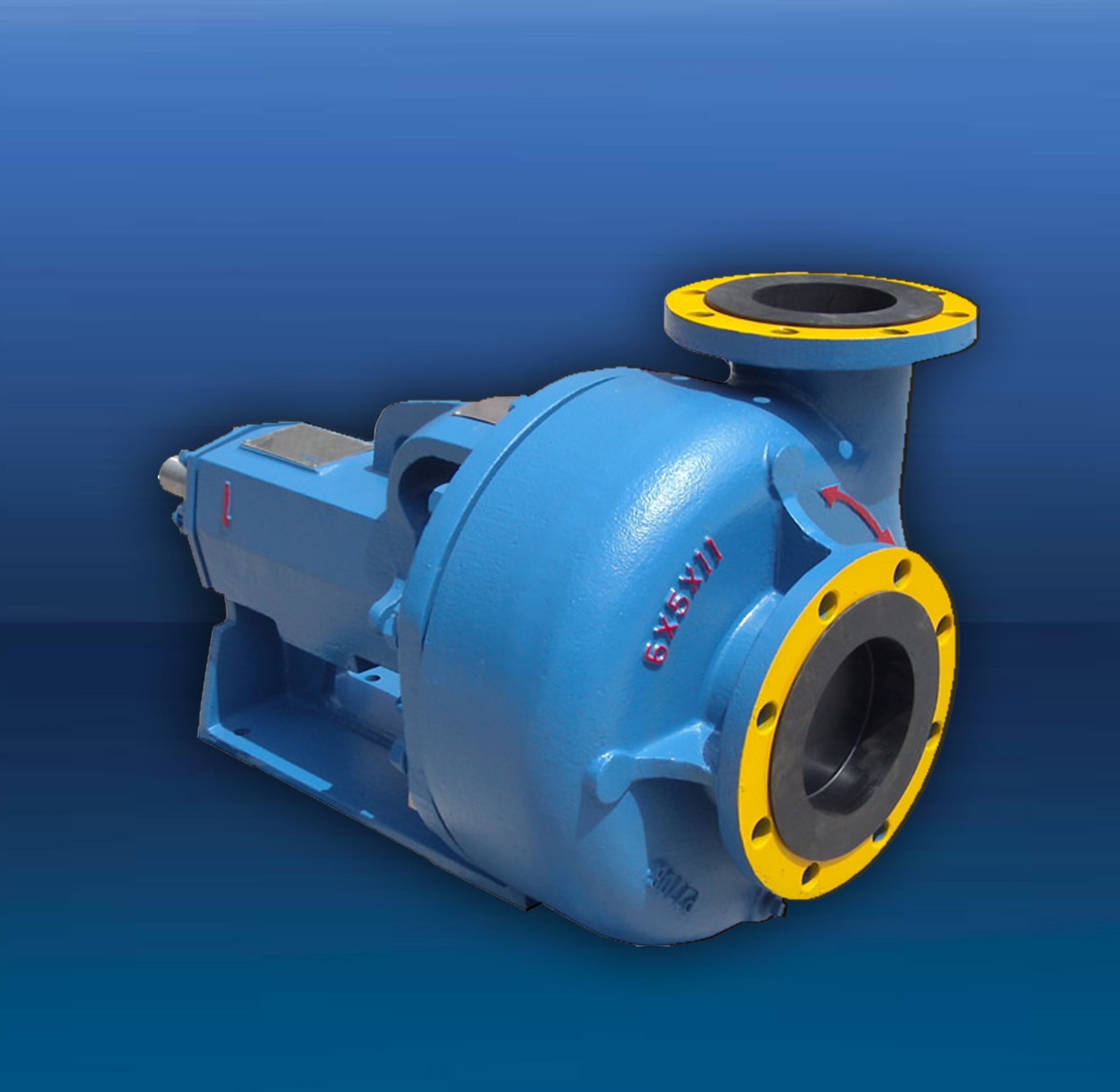
TTAAM-OM series centrifugal sand pump mainly supplies to solids control circulating system of the oilfield drill rig and can be used to provide drilling liquid with a certain discharge capacity and pressure to sand, desilter and mud mixer to assure these equipment work efficiently.
The TTAAM-OM8×6×11 centrifugal sand pump applies to under 3000-meter-long drilling Rigs and also can be used to supply mud to the triplex mud pump as a filling pump.
The pump is constituted of pump shell, impellers, bearing block, pump axle, bearing, shaft coupling, wearing plate, seal apparatus, oil seal, motor and base.

This rig features a Mission 4-by-5 centrifugal pump. Courtesy of Higgins Rig Co.Returning to the water well industry when I joined Schramm Inc. last year, I knew that expanding my mud pump knowledge was necessary to represent the company"s mud rotary drill line properly. One item new to me was the centrifugal mud pump. What was this pump that a number of drillers were using? I had been trained that a piston pump was the only pump of any ability.
As I traveled and questioned drillers, I found that opinions of the centrifugal pumps varied. "Best pump ever built," "What a piece of junk" and "Can"t drill more than 200 feet with a centrifugal" were typical of varying responses. Because different opinions had confused the issue, I concluded my discussions and restarted my education with a call to a centrifugal pump manufacturer. After that conversation, I went back to the field to continue my investigation.
For the past eight months, I have held many discussions and conducted field visits to understand the centrifugal pump. As a result, my factual investigation has clearly proved that the centrifugal pump has a place in mud rotary drilling. The fact also is clear that many drilling contractors do not understand the correct operational use of the pump. Following are the results of my work in the field.
High up-hole velocity - High pump flow (gpm) moves cuttings fast. This works well with lower viscosity muds - reducing mud expense, mixing time and creating shorter settling times.
Able to run a desander - The centrifugal"s high volume enables a desander to be operated off the pump discharge while drilling without adding a dedicated desander pump.
6. Sticky clays will stall a centrifugal pump"s flow. Be prepared to reduce your bit load in these conditions and increase your rpm if conditions allow. Yes, clays can be drilled with a centrifugal pump.
7. Centrifugal pumps cannot pump muds over 9.5 lbs./gal. Centrifugal pumps work best with a 9.0 lbs./gal. mud weight or less. High flow rate move cuttings, not heavy mud.
The goal of this article has been to increase awareness of the value of the centrifugal pump and its growing use. Although the centrifugal pump is not flawless, once its different operating techniques are understood, drilling programs are being enhanced with the use of this pump.
If you wish to learn more, please talk directly to centrifugal pump users. Feel free to call me at 314-909-8077 for a centrifugal pump user list. These drillers will gladly share their centrifugal pump experiences.
When choosing a size and type of mud pump for your drilling project, there are several factors to consider. These would include not only cost and size of pump that best fits your drilling rig, but also the diameter, depth and hole conditions you are drilling through. I know that this sounds like a lot to consider, but if you are set up the right way before the job starts, you will thank me later.
Recommended practice is to maintain a minimum of 100 to 150 feet per minute of uphole velocity for drill cuttings. Larger diameter wells for irrigation, agriculture or municipalities may violate this rule, because it may not be economically feasible to pump this much mud for the job. Uphole velocity is determined by the flow rate of the mud system, diameter of the borehole and the diameter of the drill pipe. There are many tools, including handbooks, rule of thumb, slide rule calculators and now apps on your handheld device, to calculate velocity. It is always good to remember the time it takes to get the cuttings off the bottom of the well. If you are drilling at 200 feet, then a 100-foot-per-minute velocity means that it would take two minutes to get the cuttings out of the hole. This is always a good reminder of what you are drilling through and how long ago it was that you drilled it. Ground conditions and rock formations are ever changing as you go deeper. Wouldn’t it be nice if they all remained the same?
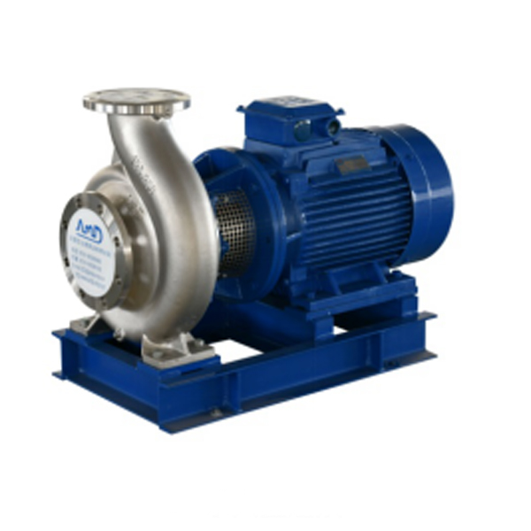
Centrifugal-style mud pumps are very popular in our industry due to their size and weight, as well as flow rate capacity for an affordable price. There are many models and brands out there, and most of them are very good value. How does a centrifugal mud pump work? The rotation of the impeller accelerates the fluid into the volute or diffuser chamber. The added energy from the acceleration increases the velocity and pressure of the fluid. These pumps are known to be very inefficient. This means that it takes more energy to increase the flow and pressure of the fluid when compared to a piston-style pump. However, you have a significant advantage in flow rates from a centrifugal pump versus a piston pump. If you are drilling deeper wells with heavier cuttings, you will be forced at some point to use a piston-style mud pump. They have much higher efficiencies in transferring the input energy into flow and pressure, therefore resulting in much higher pressure capabilities.
Piston-style mud pumps utilize a piston or plunger that travels back and forth in a chamber known as a cylinder. These pumps are also called “positive displacement” pumps because they literally push the fluid forward. This fluid builds up pressure and forces a spring-loaded valve to open and allow the fluid to escape into the discharge piping of the pump and then down the borehole. Since the expansion process is much smaller (almost insignificant) compared to a centrifugal pump, there is much lower energy loss. Plunger-style pumps can develop upwards of 15,000 psi for well treatments and hydraulic fracturing. Centrifugal pumps, in comparison, usually operate below 300 psi. If you are comparing most drilling pumps, centrifugal pumps operate from 60 to 125 psi and piston pumps operate around 150 to 300 psi. There are many exceptions and special applications for drilling, but these numbers should cover 80 percent of all equipment operating out there.
The restriction of putting a piston-style mud pump onto drilling rigs has always been the physical size and weight to provide adequate flow and pressure to your drilling fluid. Because of this, the industry needed a new solution to this age-old issue.
As the senior design engineer for Ingersoll-Rand’s Deephole Drilling Business Unit, I had the distinct pleasure of working with him and incorporating his Centerline Mud Pump into our drilling rig platforms.
In the late ’90s — and perhaps even earlier — Ingersoll-Rand had tried several times to develop a hydraulic-driven mud pump that would last an acceptable life- and duty-cycle for a well drilling contractor. With all of our resources and design wisdom, we were unable to solve this problem. Not only did Miller provide a solution, thus saving the size and weight of a typical gear-driven mud pump, he also provided a new offering — a mono-cylinder mud pump. This double-acting piston pump provided as much mud flow and pressure as a standard 5 X 6 duplex pump with incredible size and weight savings.
The true innovation was providing the well driller a solution for their mud pump requirements that was the right size and weight to integrate into both existing and new drilling rigs. Regardless of drill rig manufacturer and hydraulic system design, Centerline has provided a mud pump integration on hundreds of customer’s drilling rigs. Both mono-cylinder and duplex-cylinder pumps can fit nicely on the deck, across the frame or even be configured for under-deck mounting. This would not be possible with conventional mud pump designs.
The second generation design for the Centerline Mud Pump is expected later this year, and I believe it will be a true game changer for this industry. It also will open up the application to many other industries that require a heavier-duty cycle for a piston pump application.
A wide variety of centrifugal mud pump for drilling rig options are available to you, such as 1 year, not available and 3 years.You can also choose from new, centrifugal mud pump for drilling rig,as well as from energy & mining, construction works , and machinery repair shops centrifugal mud pump for drilling rig, and whether centrifugal mud pump for drilling rig is 1.5 years, 6 months, or unavailable.

Explore the various drilling rig centrifugal pump products available for wholesale at Alibaba.com. Get a drilling rig centrifugal pump for drilling water wells, water exploration holes, geological exploration, coal mines, and other kinds of mining. Some drilling rig centrifugal pump options use caterpillar tread to move. Others use rubber tires, while others require a separate means of transport. Caterpillar tread propulsion can climb up to 25 degrees inclination. Some products in the range are capable of drilling over 200 meters, while others are only used for open-pit mining with depths of around 3 meters. Drilling can be done vertically downwards, horizontally, or in a slanting direction. Drilling speed depends on the power of the machine and the general hardness of the surface. The hole diameter can vary from 90mm to 200mm.
drilling rig centrifugal pump options also include an air compressor, a mud pump, drilling rods of various sizes, connectors, and a drilling tower. Drilling is done using drill bits of various shapes, sizes, and compositions. You can choose between diamond bits, alloy ring-shaped bits, 3-wing alloy bits, PDC bits, and hammer bits. Each drill bit uses different drilling methods, including rotary, percussion, blast hole, and core drilling.
Smaller products have a lifting power of around 25 kilonewtons and weigh about 2,500kgs. They’re ideal for small-scale drillings such as farms and homes. Larger ones are faster with more power, making them ideal for commercial use. Browse through Alibaba.com and find a drilling rig centrifugal pump that’s ideal for your work scope. Buy mine drilling rigs for your wholesale business at competitive prices. Chinese wholesalers provide you with customization options and great after-sales services.
A well-placed suction stabilizer can also prevent pump chatter. Pump chatter occurs when energy is exchanged between the quick opening and closing of the reciprocating pump’s valves and the hammer effect from the centrifugal pump. Pump isolation with suction stabilizers is achieved when the charge pumps are isolated from reciprocating pumps and vice versa. The results are a smooth flow of pumped media devoid of agitating energies present in the pumped fluid.

AfghanistanAlbaniaAlgeriaAmerican SamoaAndorraAngolaAnguillaAntarcticaAntigua and BarbudaArgentinaArmeniaArubaAustraliaAustriaAzerbaijanBahamasBahrainBangladeshBarbadosBelarusBelgiumBelizeBeninBermudaBhutanBoliviaBonaire, Sint Eustatius and SabaBosnia and HerzegovinaBotswanaBouvet IslandBrazilBritish Indian Ocean TerritoryBrunei DarussalamBulgariaBurkina FasoBurundiCabo VerdeCambodiaCameroonCanadaCayman IslandsCentral African RepublicChadChileChinaChristmas IslandCocos IslandsColombiaComorosCongoCongo, Democratic Republic of theCook IslandsCosta RicaCroatiaCubaCuraçaoCyprusCzechiaCôte d"IvoireDenmarkDjiboutiDominicaDominican RepublicEcuadorEgyptEl SalvadorEquatorial GuineaEritreaEstoniaEswatiniEthiopiaFalkland IslandsFaroe IslandsFijiFinlandFranceFrench GuianaFrench PolynesiaFrench Southern TerritoriesGabonGambiaGeorgiaGermanyGhanaGibraltarGreeceGreenlandGrenadaGuadeloupeGuamGuatemalaGuernseyGuineaGuinea-BissauGuyanaHaitiHeard Island and McDonald IslandsHoly SeeHondurasHong KongHungaryIcelandIndiaIndonesiaIranIraqIrelandIsle of ManIsraelItalyJamaicaJapanJerseyJordanKazakhstanKenyaKiribatiKorea, Democratic People"s Republic ofKorea, Republic ofKuwaitKyrgyzstanLao People"s Democratic RepublicLatviaLebanonLesothoLiberiaLibyaLiechtensteinLithuaniaLuxembourgMacaoMadagascarMalawiMalaysiaMaldivesMaliMaltaMarshall IslandsMartiniqueMauritaniaMauritiusMayotteMexicoMicronesiaMoldovaMonacoMongoliaMontenegroMontserratMoroccoMozambiqueMyanmarNamibiaNauruNepalNetherlandsNew CaledoniaNew ZealandNicaraguaNigerNigeriaNiueNorfolk IslandNorth MacedoniaNorthern Mariana IslandsNorwayOmanPakistanPalauPalestine, State ofPanamaPapua New GuineaParaguayPeruPhilippinesPitcairnPolandPortugalPuerto RicoQatarRomaniaRussian FederationRwandaRéunionSaint BarthélemySaint Helena, Ascension and Tristan da CunhaSaint Kitts and NevisSaint LuciaSaint MartinSaint Pierre and MiquelonSaint Vincent and the GrenadinesSamoaSan MarinoSao Tome and PrincipeSaudi ArabiaSenegalSerbiaSeychellesSierra LeoneSingaporeSint MaartenSlovakiaSloveniaSolomon IslandsSomaliaSouth AfricaSouth Georgia and the South Sandwich IslandsSouth SudanSpainSri LankaSudanSurinameSvalbard and Jan MayenSwedenSwitzerlandSyria Arab RepublicTaiwanTajikistanTanzania, the United Republic ofThailandTimor-LesteTogoTokelauTongaTrinidad and TobagoTunisiaTurkmenistanTurks and Caicos IslandsTuvaluTürkiyeUS Minor Outlying IslandsUgandaUkraineUnited Arab EmiratesUnited KingdomUnited StatesUruguayUzbekistanVanuatuVenezuelaViet NamVirgin Islands, BritishVirgin Islands, U.S.Wallis and FutunaWestern SaharaYemenZambiaZimbabweÅland Islands

An innovative product policy and continuous advancement of essential design features make this pump a powerful, yet economical standard unit with a broad range of applications.
Professional China Mud Pump - BNS series Single Stage, End Suction Norm Centrifugal pumps – Beken, The product will supply to all over the world, such as: , , ,

This invention relates to apparatus useful in connection with the drilling of wells, such as oil wells, wherein a mud pump is used to circulate drilling mud under pressure through a drill string, down to and around the drill bit and out the annulus of the bore hole of the well to a mud reservoir; the apparatus of the present invention being useful for simultaneously degassing drilling mud and supercharging the mud pump.
In the drilling of deep wells, such as oil wells, it is common practice to penetrate the earth with a drill bit supported on a drill string in the bore of the well being drilled. In order to lubricate the drill bit, protect the well against blowouts, etc., it is conventional practice to circulate mud under pressure through the drill string down to and around the drill bit and up the annulus between the drill string and the bore of the well. Mud flowing from the well is passed through a suitable device such as a shaker, etc., in order to remove drill cuttings, etc., and is then delivered to a mud reservoir, such as a mud tank, for recirculation to the mud pump for pressured injection into the well.
It is also conventional practice to use a mud pump, such as a duplex or triplex mud pump comprising reciprocating pistons mounted in cylinders for pressuring the incoming drilling mud and delivering it to the well bore under pressure. The operation and construction of mud pumps is well known to those of ordinary skill in the art, as illustrated, for example, by the textbook "Mud Pump Handbook" by Samuel L. Collier (Gulf Publishing Company, Houston, Tex., 1983).
It is known, as explained in the Collier handbook, that the efficiency of a mud pump can be significantly improved by supercharging the pump; that is, by delivering drilling mud under pressure to the mud pump inlet to the cylinders containing the reciprocating pumping pistons.
It is also known to remove occluded gasses such as air, methane, etc., from drilling mud before it is delivered to the mud pump as illustrated, for example, by Burgess U.S. Pat. No. 3,973,930, Burgess U.S. Pat. No. 3,999,965 and Burgess U.S. Pat. No. 4,084,946.
Other drilling mud degassing devices are known to the art, such as those disclosed in Phillips et al. U.S. Pat. No. 4,088,457, Brown et al. U.S. Pat. No. 4,113,452, Egbert U.S. Pat. No. 4,365,977, Gowan et al. U.S. Pat. No. 4,397,659, etc.
Mud pumps used for delivering drilling mud under pressure to the bore hole of a well are conventionally of the type wherein a reciprocating piston in a cylinder is used to pressure drilling mud delivered to the cylinder for delivery to the well bore. Normally, two or three such cylinders are used, such pumps being conventionally referred to as duplex and triplex pumps. During each stroke of the piston, the piston is initially accelerated by an appropriate drive means, such as a crank shaft, from a starting position to a midcylinder position, and then decelerated to a final position within the cylinder. This constantly changing rate of motion of a reciprocating piston can result in knocking, cavitation, etc., all of which impair the efficiency of the pump. It is known to use centrifugal pumps, commonly known as superchargers, in order to deliver drilling mud to the inlet of the cylinder under pressure in order to alleviate such problems and improve the efficiency of operation of the pump.
It is undesirable to recirculate drilling mud containing occluded gases to a well bore, and therefore it is common practice to remove a significant portion of occluded gas from the drilling mud before it is recirculated to the mud pump. Normally, separate pieces of equipment that operate independently of each other are used for supercharging the mud pump and for degassing the drilling mud.
It has been discovered in accordance with the present invention that a drilling mud degasser of the type disclosed in the Burgess patents can be modified to simultaneously degas drilling mud and to supercharge the mud pump to which the degassed mud is to be delivered.
This is accomplished in accordance with the present invention through the provision of a device for simultaneously supercharging a mud pump having pistons reciprocably mounted in cylinders while degassing drilling mud to be delivered to said pistons comprising:
vacuum chamber means for continuously accelerating and centrifuging drilling mud under vacuum to thereby substantially completely remove occluded gas from the drilling mud,
a first conduit interconnecting said vacuum chamber with a drilling mud reservoir for delivering drilling mud to be degassed to said vacuum chamber means,
a first valve controlled branch conduit interconnecting said second conduit with said drilling mud reservoir for delivering drilling mud to said drilling mud reservoir when the pressure in said second conduit exceeds a predetermined value, and
a second branch conduit containing normally closed flow control means interconnecting said second conduit with said first conduit and said drilling mud reservoir operable on loss of pressure in said second conduit to permit flow of drilling mud directly from said drilling mud reservoir to said second conduit.
Referring now to the drawing, there is shown a supercharging drilling mud degasser 10 of the present invention which comprises a degassing chamber designated generally by the number 12, a power source such as an electric powered motor or a hydraulically powered motor designated generally by the number 14, a vacuum blower such as a regenerative vacuum blower, designated generally by the number 16, a gear box designated generally by the number 18, an evacuation pump designated generally by the number 20 and a drilling mud chamber designated generally by the number 22.
In accordance with this construction, there is provided a drilling mud degasser of the type shown in Burgess U.S. Pat. No. 4,084,946, housed in a cylindrical pressure vessel 24. The motor 14 is supported on vacuum blower 16 which, in turn, is supported by vacuum motor support 26 and vacuum blower brackets 28. To facilitate movement of the degasser 10, motor handling brackets 30 may be provided on the top of the motor 14 to which the hook of a crane or other appropriate means (not shown) may be attached.
Drilling mud pump impeller 42 is fixed to the centrifuge tube 40 for rotation therewith within the housing 46 of drilling mud evacuation pump 20. Cross braces 48 mounted in the cylindrical vessel 24 support lower stops 50 and upper stops 52 for an annular float 56 that surrounds the slots of the centrifuge tube 40 and partially closes them, such that the free area of the slots will be determined by the relative position of the annular float 56.
A drilling mud inlet 60 is connected to the bottom of the housing 46 for the evacuation pump 20 for the delivery of degassed drilling mud thereto. Drilling mud is delivered to the slotted centrifuge tube 40 by an inlet conduit 62 which preferably terminates inside the housing 46 for the evacuation pump 20. The top of the inlet line 62 is spaced from the bottom of the slotted centrifuge tube 40 so that the rotating centrifuge tube 40 can rotate freely without bearing upon the top of the inlet line 62. The resultant "controlled seepage" of fluid from the inlet tube 62 into the evacuation pump 20 provides a low pressure area for high effeciency scanvenging of occluded gases. Also, there is no need for bearings and seals at the bottom of the slotted centrifuge tube 40.
With this construction there is also provided an outlet line or conduit 66 connected with the discharge side of the evacuation pump 20 and extending through the wall of the cylinder 24 for connection with a suitable first conduit 68 leading, for example, to a triplex pump 70 for injecting drilling mud under pressure into a well penetrating a subterranean formation in order to lubricate the drill bit, protect the well against blow outs, etc., it is conventional practice to circulate mud under pressure through the drill string down to and around the drill bit and up the annulus beteen the drill string and the bore of the well. Mud flowing from the well is passed through a suitable device such as a shaker, etc. (not shown) in order to remove drill cuttings, etc., and is then delivered to a mud reservoir, such as a mud tank 84, for recirculation to the mud pump 70 in the manner described herein for pressured injection into the well.
The first conduit 68 may comprise, for example, a connecting pipe 72 interconnecting the outlet line 66 with the flexible hose 74 which, in turn, is connected to a mud pump inlet line 76. The flexible hose 74, which is provided for ease in alignment, may be secured to the connecting pipe 72 by a clamp 78 of any suitable construction and to the mud pump inlet line 76 by a clamp 80 of any suitable construction.
A second conduit 82 interconnects a drilling mud reservoir such as a mud tank 84 with the inlet conduit 62 leading to the slotted centrifuge tube 40 for the degasser 10.
Preferably, the second conduit 82 is provided with valve means such as a butterfly valve 86 which may be used to close the second conduit 82 when both the drilling mud degasser 10 and the mud pump 70 are to be idled for any appreciable time.
A first branch conduit 88 interconnects the first conduit 68 with the mud tank 84 and contains pressure sensitive control means such as a spring biased relief valve 90 in order to permit drilling mud to recycle from the first conduit 68 to the mud tank 84 when the pressure in the first conduit 68 exceeds a predetermined value.
A second branch conduit 92 interconnects the first conduit 68 with the inlet conduit 62 and the second conduit 82. The second branch conduit 92 contains normally closed flow control means such as a check valve 94 to permit flow of drilling mud directly from the mud tank 84 to the mud pump 70 if the pressure in the first conduit 68 falls below a predetermined value.
During drilling operations, rotation of an appropriate vacuum blower such as a regenerative vacuum blower by the drive shaft 32 for the motor 14 will generate a vacuum in the degassing chamber 12 such that drilling mud sprayed from the slots in the centrifuge tube 40 will tend to impact upon the inner sides of the degassing chamber 12 thereby initiating degassing of the drilling mud fed through the inlet line 62. Rotation of the centrifuge tube 40 will impart upward accelerating rotary motion to partially degassed drilling mud delivered thereto through the line 62 and the resultant spraying of the thus centrifuged drilling mud through the slots in the centrifuge tube 40 will result in a sheet of drilling mud being sprayed onto and impacting on the inner walls of the degassing chamber 12 to thus substantially complete the removal of gas from the drilling mud. The thus degassed drilling mud will flow downwardly past cross braces 48 and into inlet 60 leading through the housing 46 of the evacuation pump 20 where the impeller 42 will repressure the now degassed drilling mud for discharge through the outlet line 66 which is interconnected with a triplex pump 70 by first conduit 68 for supercharging the pump 70, which further pressures the degassed drilling mud for injection into a well bore penetrating a subterranean formation.
In order to prevent the entrainment of drilling mud droplets in the gases withdrawn through the gas evacuation suction pipe 98, a splatter plate 100 is provided in the degassing chamber 12 and a combination of a foam separation impeller 36 with a splatter disk 102 is provided adjacent the top of the degassing chamber 12 so that gas liberated in the vacuum chamber must follow a sinuous path arriving at the upper chamber gas evacuation suction pipe 98.
In accordance with the present invention, the motor 14 is operated such that drilling mud delivered to the first conduit 68 will be at a predetermined appropriate supercharging pressure for the mud pump 70, (e.g. a pressure of about 20 to 30 psig).
The pressure sensitive control means, such as a spring biased relief valve 90, is set to open at a predetermined pressure about 5 to 10 psi higher than the desired pressure in the first conduit 68 so that, if the indicated pressure limit is exceeded, the pressure relief valve 90 will open in order to permit drilling mud to recycle to the mud tank 84.
This will happen if the mud pump 70 malfunctions and also when the mud pump 70 is turned off, as will happen from time to time. For example, it is necessary to turn off the mud pump 70 during drilling operations when a new stand of drill pipe is to be added to the drill string. It is also necessary to turn off the mud pump 70 when the drill string is being withdrawn from the well bore in order to replace the drill bit, while well logging operations are in progress, if it is necessary to "fish" for a piece of equipment lost down the hole, etc. However, if the drilling mud in the mud tank 84 is permitted to remain quiescent for more than a limited period of time, the drilling mud may start to gel and/or to stratify. This problem is conventionally avoided by providing a separate agitator (not shown) for the mud tank 84 in order to stir the drilling mud when the mud pump 70 is idle. However, through the provision of the present invention, there is no need for a separate agitator for the mud tank 84 because recirculation of drilling mud through the first branch conduit 88 will impart a "roiling" motion or agitation to the drilling mud in mud tank 84 to inhibit gelling and/or stratification of the drilling mud while the mud pump 70 is idle.
Loss of pressure in the first conduit 68 can occur in the event of malfunction of the degasser 10 or in the event it is desired to shut the degasser 10 down for a limited period of time. In this event, drilling mud flows directly from the mud tank 84 through the second conduit 82, the second branch conduit 92 and the flexible hose 74 to the mud pump 70 so that the mud pum 70 is not "starved" for drilling mud to be injected into the well.

Within the petroleum industry centrifugal pumps are necessary in order to process fluids especially hydrocarbons. Another important application within the petroleum industry is in the mud circuit on a drilling rig. On drilling rigs, mud which consists mainly of water and bentonite as well as of several different additives depending on many different factors is used. The heart of the mud circuit is the mud pump which is in general a high pressure piston pump. It provides the major part of head to overcome the system’s resistance. The mud is pumped through a piping system to the derrick and through the standpipe to a definite high. Now through the kelly hose via the gooseneck into the upper kelly cock. It flows through the Kelly and the lower kelly cock into the drill string down the borehole. At its end, the mud leaves the drilling collars through the drilling bit.
1. Select a pump to handle the highest anticipated flow. Select an impellersize to provide sufficient discharge head to overcome friction in the lines,lift the fluid as required, and have sufficient head remaining to operatethe equipment being fed.
Initially this guideline suggested that the pump flange size be selected to provide the highest anticipated flow, even though the flange size has nothing to do with the flow rate. Most pump curves are listed in terms of the flange sizes. The size of the pump impeller housing increases as the flange size increases. An impeller rotating at constant speed will create a constant head independent of the size of the housing or the flanges. An impeller that fits inside a 2×3, 3×4, 4×5, or 5×6 pump will produce the same head in each pump if it is rotated at the same speed. Because the housing of a pump with a 2-inch and 3-inch flange is smaller, the internal friction at a high flow rate will be greater than a 56 pump. This means that the capacity of the various pump sizes will be indicated by their flange sizes. The committee decided to only indicate that the pump should be selected to handle the highest anticipated flow rate, instead of indicating that the flange size is commonly used to specify pump size.
2.Install the centrifugal pump with a flooded suction that is sumped so thatsufficient submergence is available to prevent vortexing or air-locking.Foot valves are not needed or recommended with flooded suctions.
A small influx of air into the suction of a centrifugal pump can create cavitation problems and diminished flow. As the air enters the chamber with the impeller, it tends to concentrate in the center of the impeller because of the centripetal acceleration of the drilling fluid.
The liquid continues to move through the pump. The air does not always continue to the impeller tip, but tends to remain in the center of the impeller. This bubble of air forms a barrier for the incoming fluid, which diminishes the flow rate into the pump. The air also experiences a significant decrease in pressure—possibly even below atmospheric pressure. This causes implosions of vapor bubbles that can remove metal from the impeller. The pump will sound as if it is pumping gravel. If it continues in this mode for a long period of time, the impeller will be severely damaged.
Flooded suctions tend to eliminate most of the air influx problems but sometimes a small vortex will form in the mud tank. These small vortexes can entrain a significant amount of area. Increasing agitation in the tanks may prevent a coherent cylinder of air from reaching the suction line. Alternatively, a plate can be installed in the tank to interrupt the formation of a vortex.
In some cases, a centrifugal pump is placed on the ground above a pond or buried tank. Foot valves are needed if the centrifugal pump is operated above the liquid level of the suction tank. Foot valves are check valves that prevent the suction line from draining when the pump is turned off. Care must be taken to eliminate tiny air leaks in the suction line because the absolute pressure will be below atmospheric pressure. The pump and suction line should be filled with fluid before the pump motor is started. Centrifugal pumps do not move air very well.
A centrifugal pump suction can only lift fluid a certain height above a liquid level. These heights are determined by observing the NPSH (negative pressure suction head) values listed on the centrifugal pump curves. If the NPSH is exceeded, cavitation can destroy the impeller.
Horizontal pipes will fill with solids until the flow rate reaches 5 ft/sec. Barite in equalizing lines between mud tanks is normally settled until the velocity between the tanks reaches 5 ft/sec. Increasing the diameter of connection lines only causes more barite to settle. Above 10 ft/sec, pressure losses in the pipe become too great. Elbows and swages tend to cause turbulence in the flow stream, which can lead to cavitation.
5. Eliminate manifolding. One suction and one discharge per pump ismost cost effective over time. Do not manifold two pumps on the samesuction line. Do not pump into the same discharge line with two or morepumps.
Flexibility of piping so fluid can be pumped from any tank through any equipment to any other tank has created more problems over the years than just about any other concept. A properly plumbed system should require only one suction and one discharge for each piece of solids-removal equipment. Ignoring this rule allows rig hands the opportunity to open or close the wrong valves. A leaky or incorrectly opened valve can reduce drilled-solids removal efficiency by up to 50%. This translates to an expensive drilling-fluid system. This problem can be eliminated by storing an extra pump and motor. Arrange the centrifugal pumps and motors so that they may be easily replaced. If a pump or motor fails, simply replace the unit. The damaged unit can be replaced during routine maintenance. Two centrifugal pumps in parallel will not double the head available to equipment because a centrifugal pump is a constant head device. For example, visualize a standpipe that is constantly filled with fluid. If two standpipes of approximately the same height are connected, the flow from both pipes will almost equal the flow from one standpipe. If fluid stands lower in one standpipe than the other. fluid will flow from the highest standpipe to the lowest standpipe. This same flow occurs when two pumps are connected in parallel—fluid will flow backward through one of the pumps.
6. Install a pressure gauge between the pump discharge and the first valve.When the valve is closed briefly, the pressure reading may be used fordiagnostic evaluation of the pump performance.
A centrifugal pump uses the smallest amount of power when no fluid is moving through the pump (that is, when the discharge valve is completely closed). If the valve remains closed for longer than 5 minutes, the fluid within the pump will become hot from the impeller agitation. This hot fluid may damage the seals. Closing the valve for a short time allows a good reading of the no-flow head produced by the pump. This reading should be compared with the pump manufacturer’s charts. The diameter of the impeller can then be determined. (A pump may be stamped 5X6X14. This means that it could house a 14-inch impeller but it does not mean that it has a 14-inch impeller. The impeller size is adjusted so the pump will deliver the proper head.) After the pump has been in service for a period of time, the pressure reading will assess the condition of the impeller. This eliminates the need to dismantle the pump for inspection. If the manifold pressure is incorrect, reading the pump no-flow discharge head will assist in troubleshooting.
7.Keep air out of the pump by degassing the mud, having adequate suctionline submergence, and installing baffles to break mixer vortices. Properly sized, baffled, and agitated compartments will not vortexunless the drilling fluid level becomes extremely low.
Centrifugal pumps cannot pump aerated fluid. The air tends to gravitate toward the center of the impeller while the liquid moves toward the outside. This creates an air bubble at the center of the impeller. When the air bubble becomes as large as the suction line diameter, fluid will no longer enter the pump. This is called airlock. Only a small cylinder of air vortexing into the pump is sufficient to prevent the pump form moving liquid. Since the air accumulates over a period of time, a small vortex the size of a pencil is sufficient to eventually shut down a 6×8 pump. Baffles are inexpensive and easily installed in an empty tank. Any vertical surface that disrupts the swirling motion of the fluid in a compartment is usually sufficient to destroy a vortex. Rig pump efficiency can decrease from 99 to 85% efficiency if the drilling fluid content rises to 6% volume. Air in the drilling fluid may be calculated by measuring the pressurized and unpressurized mud weight.
8. Do not restrict the flow to the suction side of the pump. Starving thepump suction causes cavitation and this will rapidly damage the pump.When a pump begins cavitating, small vacuum bubbles adjacent to the impeller surface start imploding. The pump sounds as if it is pumping gravel. The implosions quickly remove metal from the surface to the impeller blade. In a very short period of time, holes will appear in the metal. Important: Do not close a valve on the suction line while the pump is running!
Starving the suction will decrease the output head. If the head, or pressure produced by the pump, is too high, change to a smaller diameter impeller. On a temporary basis, a discharge valve can be partially closed. On a long-term basis, however, considerable valve erosion will occur so a new, properly sized impeller is necessary. Even a large centrifugal pump is not damaged if only 10 to 20 gpm is discharged from the pump. In fact, the lower flow rates will require less horsepower to the motor than pumping fluid at a much higher flow rate.
Centrifugal pumps will pump fluid even if running in reverse. The head produced by the pump will be lower than it should be. The pressure gauge installed between the pump and the first valve will assist with the diagnosis. Usually, switching two wires in the lead-in panel box will correct the rotation.
10.Startup procedure for an electric motor–driven centrifugal pump with avalve on the discharge side between the pump and the equipment beingoperated is to start the pump with the valve just slightly open. Once thepump is up to speed, open the valves slowly to full open. This approachwill reduce the startup load on the electric motor and will reduce theshock loading on equipment such as pressure gauges and hydrocyclones.
An alternative startup procedure is to completely close thedischarge valve before startup and then open the valve slowly immediatelyafter startup to prevent overheating and possible damage to thepump seals.
An electric motor–driven centrifugal pump will immediately try to produce a constant head when it is turned on. If the pump is pumping into an empty line, the flow rate is enormous. Very high flow rates require very high currents to the electric motor. Circuit breakers can stop the pump and avoid motor burnout. Lower horsepower is required if the pump is started with the discharge valve closed.


 8613371530291