
creative commons mud pump oil and gas brands

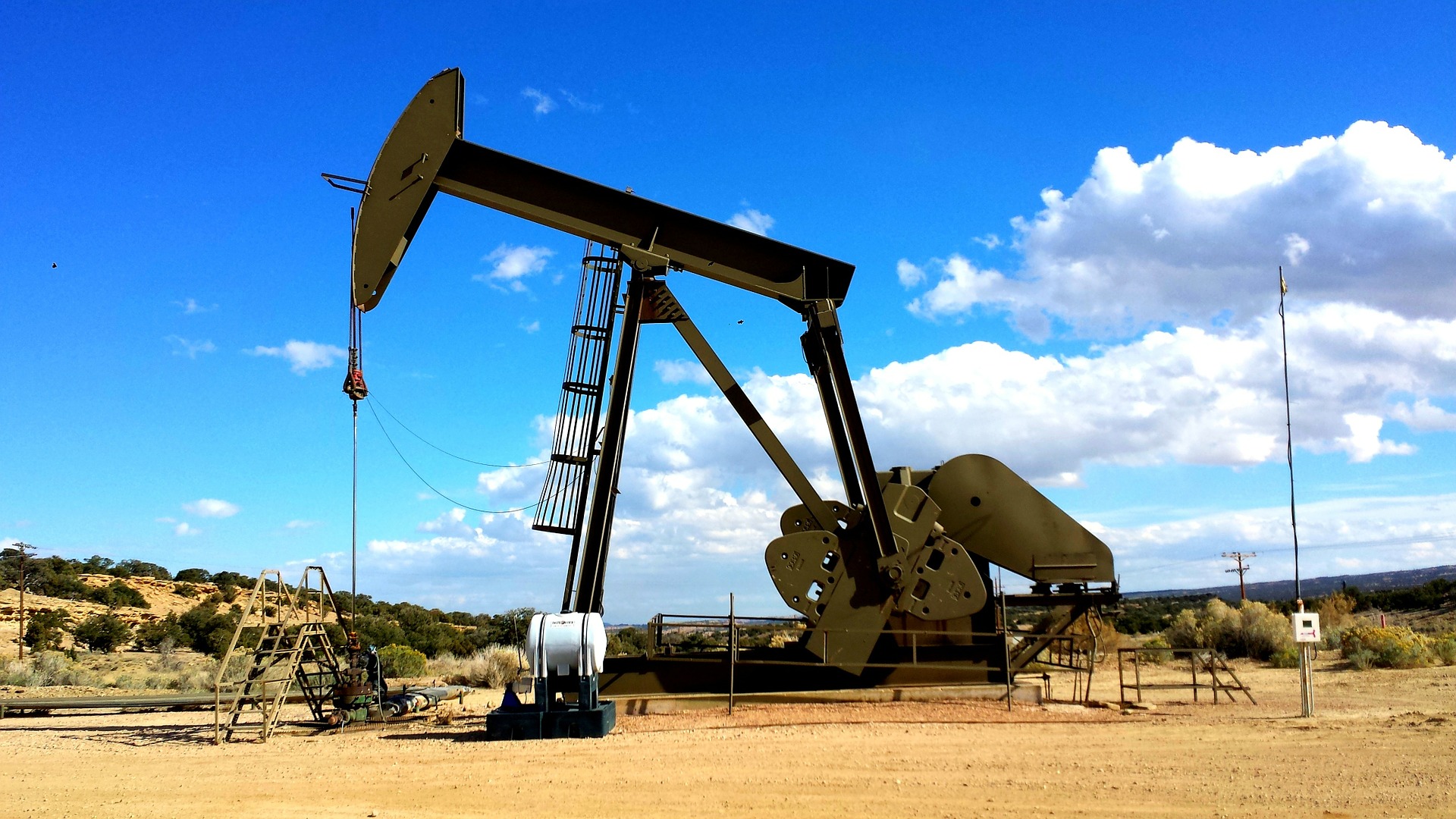
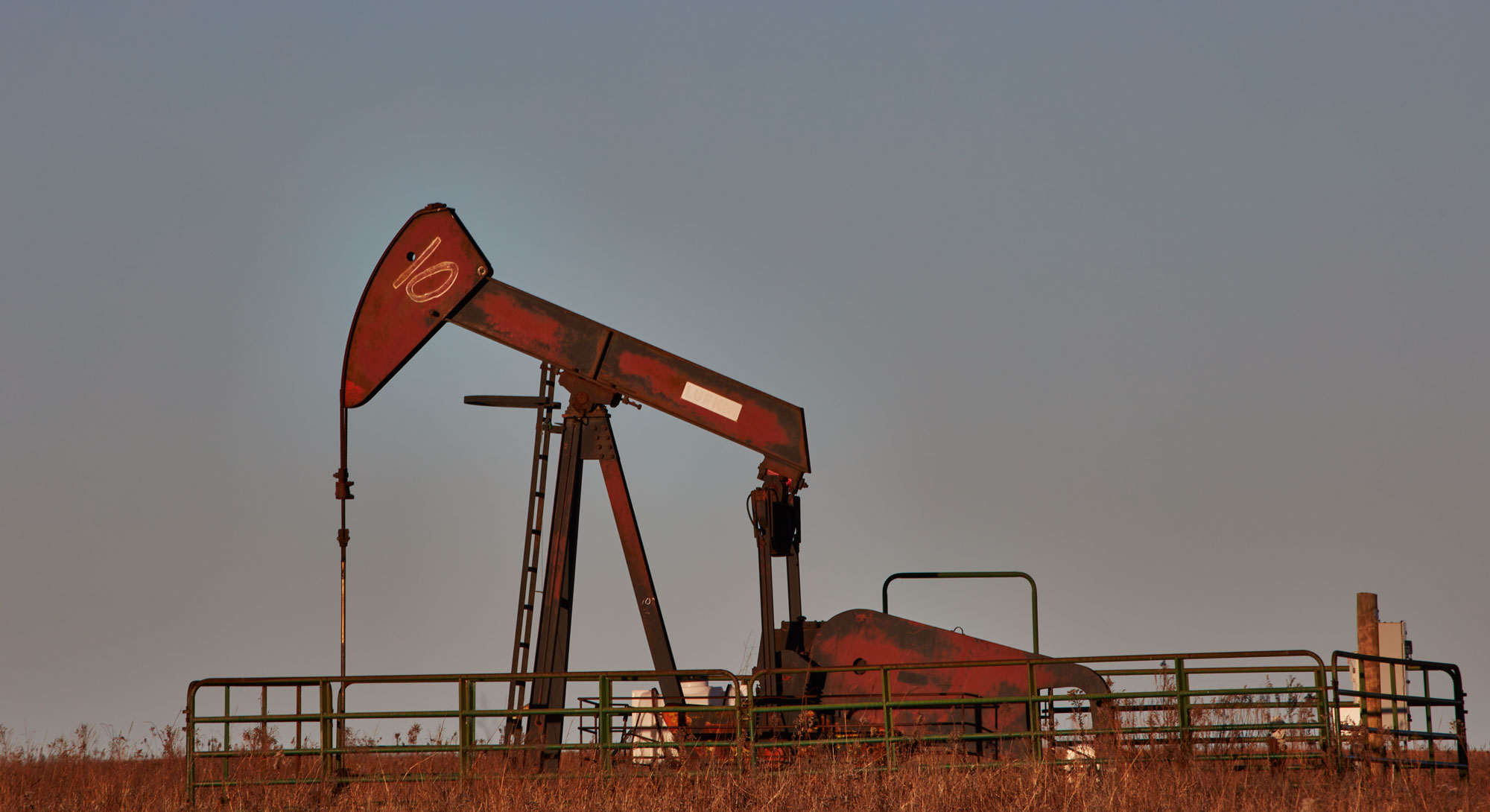
A mud pump is a reciprocating piston/plunger device designed to circulate drilling fluid under high pressure (up to 7500 PSI) down the drill string and back up the annulus.

Streamline your workflow with our best-in-class digital asset management system. Organise, control, distribute, and measure all of your digital content.

The 2,200-hp mud pump for offshore applications is a single-acting reciprocating triplex mud pump designed for high fluid flow rates, even at low operating speeds, and with a long stroke design. These features reduce the number of load reversals in critical components and increase the life of fluid end parts.
The pump’s critical components are strategically placed to make maintenance and inspection far easier and safer. The two-piece, quick-release piston rod lets you remove the piston without disturbing the liner, minimizing downtime when you’re replacing fluid parts.
If you ended up on this page doing normal allowed operations, please contact our support at support@mdpi.com. Please include what you were doing when this page came up and the Ray ID & Your IP found at the
Gardner Denver, Lewco, NOV, Oilwell, National, Varco, Woolley, Baash-Ross, Demco, Bomco, Oteco, Brown & Sharpe, Ideco, P-Quip, and Continental Emsco, and the product models referenced on this website are trademarks or registered trademarks of their respective companies. Premium Oilfield Technologies is not authorized by or affiliated with any of these companies, and no business relationship, affiliation, or endorsement is claimed or implied.
A mud pump (sometimes referred to as a mud drilling pump or drilling mud pump), is a reciprocating piston/plunger pump designed to circulate drilling fluid under high pressure (up to 7,500 psi or 52,000 kPa) down the drill string and back up the annulus. A mud pump is an important part of the equipment used for oil well drilling.
Mud pumps can be divided into single-acting pump and double-acting pump according to the completion times of the suction and drainage acting in one cycle of the piston"s reciprocating motion.
Mud pumps come in a variety of sizes and configurations but for the typical petroleum drilling rig, the triplex (three piston/plunger) mud pump is used. Duplex mud pumps (two piston/plungers) have generally been replaced by the triplex pump, but are still common in developing countries. Two later developments are the hex pump with six vertical pistons/plungers, and various quintuplexes with five horizontal piston/plungers. The advantages that these new pumps have over convention triplex pumps is a lower mud noise which assists with better measurement while drilling (MWD) and logging while drilling (LWD) decoding.
The fluid end produces the pumping process with valves, pistons, and liners. Because these components are high-wear items, modern pumps are designed to allow quick replacement of these parts.
To reduce severe vibration caused by the pumping process, these pumps incorporate both a suction and discharge pulsation dampener. These are connected to the inlet and outlet of the fluid end.
Displacement is calculated as discharged liters per minute. It is related to the drilling hole diameter and the return speed of drilling fluid from the bottom of the hole, i.e. the larger the diameter of drilling hole, the larger the desired displacement. The return speed of drilling fluid should wash away the debris and rock powder cut by the drill from the bottom of the hole in a timely manner, and reliably carry them to the earth"s surface. When drilling geological core, the speed is generally in range of 0.4 to 1.0 m^3/min.
The pressure of the pump depends on the depth of the drilling hole, the resistance of flushing fluid (drilling fluid) through the channel, as well as the nature of the conveying drilling fluid. The deeper the drilling hole and the greater the pipeline resistance, the higher the pressure needed.
With the changes of drilling hole diameter and depth, the displacement of the pump can be adjusted accordingly. In the mud pump mechanism, the gearbox or hydraulic motor is equipped to adjust its speed and displacement. In order to accurately measure the changes in pressure and displacement, a flow meter and pressure gauge are installed in the mud pump.
The construction department should have a special maintenance worker that is responsible for the maintenance and repair of the machine. Mud pumps and other mechanical equipment should be inspected and maintained on a scheduled and timely basis to find and address problems ahead of time, in order to avoid unscheduled shutdown. The worker should attend to the size of the sediment particles; if large particles are found, the mud pump parts should be checked frequently for wear, to see if they need to be repaired or replaced. The wearing parts for mud pumps include pump casing, bearings, impeller, piston, liner, etc. Advanced anti-wear measures should be adopted to increase the service life of the wearing parts, which can reduce the investment cost of the project, and improve production efficiency. At the same time, wearing parts and other mud pump parts should be repaired rather than replaced when possible.

Our state-of-the-art repair facilities combine world-class equipment with over 150 years of industry leading expertise, to provide our customers with a comprehensive range of services. If you can’t come to us, we can bring our legendary expertise to you, using our full range of on-site repair and field service offerings.
The first documented spring-pole well in America was drilled in 1806 by David and Joseph Ruffner in West Virginia. It reached 58 feet in depth, containing 40 feet of bedrock. The project lasted two years.
A patent to L. Disbrow for the first four-legged derrick was given, originally in 1825 and then elaborated on in 1830. The structure consisted of legs made of square timber wood. The girts were mortised and inserted into the wooden legs with keys so the structure could be dismantled.
Men in Kentucky were drilling an exploratory well for salt brine. Instead, they hit an oil well. The pressure of the gas and oil underneath the surface forced an enormous geyser into the air. This was noted to be America’s first oil well (although there are some disputes to this claim).
J.J. Couch invented the first mechanical percussion drill, which he later perfected with the help of fellow inventor J.W. Fowle. Steam was admitted alternately to each end of a cylinder. The drill was thrown like a lance at the rock on the forward stroke, caught and then drawn back on the reverse stroke, and then thrown again. It was the first drill that did not depend on gravity. It went to work on the Hoosac Tunnel project, which bored a passage for trains through hills near North Adams, Mass.
George Bissell and Edwin L. Drake made the first successful use of a drilling rig on a commercial well drilled especially to produce oil in Pennsylvania. They drilled to 69 feet.
In June, J.C. Rathbone drilled a discovery well to 140 feet using a steam engine on the banks of the Great Kanawha River in the Charleston, W.Va., area. The well produced about 100 barrels of oil a day.
Charles Burleigh, John W. Brooks, and Stephen F. Gates patented a mechanical drill meant to be used on the Hoosac tunnel: the compressed air Burleigh drill. The tunnel spurred several innovations in drilling technology, including the earlier Couch/Fowle drill.
Edward A.L. Roberts was awarded a patent in November 1866 for what would become known as the Roberts Torpedo, a device for increasing the flow of oil by using an explosion deep in a well. The new technology revolutionized the young oil and natural gas industry by increasing production from individual wells.
Simon Ingersoll received a patent for a rock drill on a tripod mount. The drill was designed for mining and tunneling. It enabled the operator to drill at virtually any angle. He formed Ingersoll Rock Drill to capitalize on this invention, a company that is a precursor to Ingersoll-Rand.
The Bucyrus Foundry and Manufacturing Company was founded in Bucyrus, Ohio. The company later became famous in the drilling industry as Bucyrus-Erie, a maker of cable-tool rigs, but it was an early producer of steam shovels. It supplied many of the steam shovels used in the building of the Panama Canal.
Edmund J. Longyear drilled the first diamond core hole in the Mesabi Iron Range (shown above in 1903) in northern Minnesota. Shortly thereafter, he formed a contract diamond drilling company to serve the rapidly growing U.S. iron ore mining and steel industry.
John Smalley Campbell issued the first U.S. patent for the use of flexible shafts to rotate drilling bits. The patent was for dental applications, but was broad enough to cover larger scales, such as those used now in horizontal oil wells.
The Baker brothers were using their rotary method for oil well drilling in the Corsicana field of Navarro County, Texas. Their rig was powered by a mule.
Drillers at Spindletop, including brothers Curt and Al Hamill and Peck Byrd, noticed that muddied-up freshwater could help stabilize a formation and prevent borehole collapse. They started circulating it and drilling mud was born.
Captain Anthony F. Lucas at Spindletop began drilling with a steam-driven rotary rig and a double-pronged fishtail bit. The gusher at Spindletop lasted nine days and ushered in the first Texas oil boom.
Inspired by the success of Spindletop and what it meant for the future of oil drilling in Texas, Howard Hughes Sr. and Walter Sharp founded the Sharp-Hughes Tool Company. The Hughes name lives on today in the name of the company Baker-Hughes.
Edmund J. Longyear and John E. Hodge formed Longyear & Hodge, the manufacturing partnership that would eventually evolve into Boart Longyear. The company"s early drills were steam powered.
Howard Hughes Sr. and Walter Sharp introduced the Sharp-Hughes Rock Bit, which was nicknamed the "rock eater." It was suited for deep boring through medium and hard rock.
The Supreme Court of the United States ruled that Standard Oil, which at the time controlled more than 90 percent of U.S. production, was a monopoly and that the company must be broken up to create competition in the market.
Lee C. Moore patented a system that clamped and secured bracing to steel pipe legs to build a steel derrick. At that time, oil derricks were commonly wooden cable tool rigs.
The rotary table and kelly were first used. The primary function of the rotary table was to transmit torque to the drillstring via the kelly, a section of pipe with a square cross-section that slotted through a similar shape on the rotating table.
Hugh Roberts, working as a geologist for Edmund Longyear, designed a new form of technology called a core splitter, which divided cores into 3- – 5-inch lengths for better analysis. Drilling firms used Roberts"s core splitter as standard equipment.
Victor York and Walter G. Black of Standard Oil Company of California were granted a patent for driving the rotary table with a shaft. This innovation guaranteed the ongoing success of the rotary drilling method.
The first true horizontal oil well was drilled near Texon, Texas. By the early 1980s, with advancements in drilling motors and steering, the technology finally became widespread.
Cal Talc, A. J. Lynch and National Pigment Chemical merged to form Baroid Sales Company. The new company, founded to serve the growing market for products for hydraulic rotary drilling, is based in Los Angeles.
In June, the New York State Natural Gas Corporation abandoned a project after having drilled the world"s deepest cable-tool well to a depth of 11,145 feet. The well was located in Van Etten, N.Y. The project started five years earlier.
The first downhole drilling motors, or mud motors, were designed and manufactured by Dyna-Drill. The motor was based on the 1930 Moineau design for progressive cavity pumps.
General Electric Research Lab (GE) introduced a new synthetic material made of diamond grains sintered together with cobalt. This new material, Compax, could be made into various shapes and retained diamond’s natural property of extreme hardness, but not its weak cleavage planes. To make a cutter, a thin layer of the synthetic diamond material was deposited onto a disk-shaped tungsten carbide substrate so that the assembly, called a “compact,” could be attached to the bit. Bits with this kind of cutter are generically called PDC bits.
Teleco Oilfield Services Inc., together with the U.S. Department of Energy, introduced mud pulse telemetry, now a widely used method of transmitting measurement while drilling data to the surface. Commercialized in 1978, the technology had been under development since the late 1960s. Data transmitted by pulses, together with trigonometry, can give operators a three-dimensional plot of the well being drilled. Pulse telemetry improved on the slower process of wireline logging. Teleco was later acquired by Baker Hughes.
The Versa-Sonic drill rig was put into operation. Versa-Drill International Inc. and Bowser-Morner built this rig that incorporated Ray Roussy’s new sonic drill head. Roussy had worked to improve and perfect the technology over more than 20 years from original designs, which modified oscillators for drilling purposes. Sonic drills, like this one used by the Army Corps of Engineers, are now widely used for sampling.
Professors at Texas Tech University developed “zipper fracking,” which is when operators drill two wells side by side. The process allowed both wells to produce more oil and gas.

Texas at the turn of the twentieth century depended upon farming, lumber, and cattle ranching for its basic economy. While oil was drilled in Texas in the late 1890’s and early 1900, it did not produce enough to have any significance to the state’s economy. The Spindletop discovery changed everything on January 10, 1901, when oil was struck.
Spindletopis an oil field built on top of a salt dome located near Beaumont, Texas which mainly produced lumber. On that history-making day, the Spindletop gusher raged for 9 days gushing 100,000 barrels of oil per day. As a result, Texaco and Gulf Oil, now part of Chevron Corporation, were founded for the development of oil production at Spindletop.
, a Pulitzer Prize author and energy authority, claimed that the Spindletop discovery guided America into the golden age of oil. Before Spindletop, oil was mainly used as a lubricant and for burning oil lamps. The volume of the Spindletop oil made it economically feasible to use petroleum in the mass consumption of fuel.The Spindletop well, a discovery that created the greatest oil boom in America – exceeding the nation’s first oil discovery well in 1859 in Pennsylvania.
Oil has been around for hundreds of years. As far back as 1543, Spanish conquistadors used crude oil for caulking their ships and waterproofing their boots. Native American Indians drank crude oil in an attempt to cure digestive problems.
Prior to 1901, many speculated that oil was under Spindletop Hill. This was due to its vast bubbling gas seepages which ignited when lit, and the fact of having numerous sulfur springs.
In 1892, George W. Carroll,George W. O’Brien, and Patillo Higgins created the Gladys City Oil, Gas, and Manufacturing Company to do Spindletop Hill’s exploratory drilling. However, after drilling numerous dry holes, their investors lost confidence in their oil explorations.
Patillo Higgins, a one-armed mechanic and self-taught geologist, was one of the few at the time who believed that U.S. industries would soon switch fuels from coal to oil. Higgins believed thatSpindletop Hill, just four miles south of the town of Beaumont had oil. This was in spite of contrary conventional wisdom at the time. The hill formed over a million years was a result of a huge underground salt dome that moved towards the surface. Higgins had a gut feeling that by drilling down from the top of the salt dome would produce oil. Local geologists were skeptical of Higgins beliefs.
Then, Patillo Higgins quit the company to team up with Captain Anthony F. Lucas, a leading salt dome formations expert. In 1899, Lucas signed a lease agreement with the Gladys City Company and a later partnership contract with Patillo Higgins. However, after Lucas drilled to 575 feet, he ran out of money.
Lucas found additional investors James M. Guffey and John H. Galey from Pittsburgh, Pennsylvania. Their investment reduced Lucas to only a one-eighth share while Higgins was completely left out. In addition to funding, Guffey and Galey’s main contribution was bringing in AlandCurt Hamillfrom the Corsicana oilfieldwho were drilling mud experts.
Finally, on January 10, 1901, Lucas drilled to a depth of 1,139 feet and struck oil. What later become known as the “Lucas Geyser” and the “Lucas Gusher”, the gusher blew over 100 feet in the air at a rate of 100,000 barrels per day. After nine days, the gusher was finally brought under control.
According to Lamar University in Texas, the significance of the Spindletop gusher producing 100,000 barrels a day compared to the total annual Texas oil production in 1900 of only 836,000 barrels. This meant Spindletop could produce more than the previous year’s oil production in Texas in just 9 days. In addition, Spindletop produced nearly 40% of the total annual oil production of the entire U.S. in 1901.
The Spindletop-Gladys City Boomtown Museum states that:The oilfield produced 3.59 million barrels in its first year and an incredible 17.4 million barrels the next.
At the time, Spindletop became the largest gusher in the world. As a result, the little town of Beaumont turned into an oil-fueled boomtown. Its population of 8,500 quickly tripled in a month and grew to 50,000 within a year.
Besides local population growth, land values rose rapidly. In addition, by 1903, 285 wells were operating and more than 500 oil related companies were created.
As the first oilfield in the U.S. Gulf Coast, Spindletop inspired further drilling and oil discoveries in the region. Drilling in other salt fields proved to be very successful. In a short time, the Gulf Coast became a major oil region.
During that time, Texaco and Gulf Oil grew into major oil producers. Ironically, Standard Oil was completely shut out of Texas by its state antitrust laws. Standard Oil had a major monopoly in the eastern states petroleum industry. Even companies affiliated with Standard Oil were banned from Texas due to alleged improper business practices. In spite of these banishments, Standard Oil was still able to build refineries in the region because no other U.S. companies could.
Lucas first spudded in a well in October of 1900. He used a heavier, more efficient rotary type bit. In essence, Lucas popularized rotary drilling technology. Over the next three months, Lucas drilled along with the Hamill brothers trying to overcome difficult oil sands. The sand made the hole susceptible to cave-ins. Curtis Hamill solved the problem by pumping mud instead of water into the hole to flush out the drill cuttings. The mud stuck to the sides of the hole which prevented cave-ins. This was a revolutionary solution for drilling into sand. Drilling mud has been used globally ever since.
Finally, on January 10th mud started bubbling from the hole. Frightened drillers ran as six tons of four-inch drilling pipe shot out of the hole. When the well blew, Curtis Hamill was working on top of the rig. He fought for his life getting down in time. Then it calmed down for a few minutes as mud, then gas, and finally oil spurted out. That’s when Curtis Hamill returned to shut off the derrick floor machinery.
The resulting stream traveling over 1,139 feet underground blew an oil stream over 100 feet high. It took nine days to finally cap it. The flow averaged 100,000 barrels per day.
When it was capped on January 19, a large pool of oil surrounded it. When word got out, thousands of onlookers, speculators, and oilmen eventually transformed the town of Beaumont into a city.
Sidenote: Drilling companies have continuously used ingenuity to solve wellbore and drilling problems. For those interested, here are our articles aboutturbodrilling, jet drilling and wellbore cleanups.
For the first time in history, the biggest oil gusher flowed. In eight months, six more successful wells flourished on lands owned by the Gladys City Company.
Nearby land prices skyrocketed. One land seller tried to sell for the past three years at $150, then sold it for $20.000. The buyer quickly resold it within 15 minutes for $50,000. One of the wells drilled on an investment of $10,000 sold for $1,250,000.
Multi-million dollar land deals spread like wildfire. By the end of 1901, over $235 million was invested in Texas oil. But not every investment was successful. Some became instant millionaires while others lost everything.
A second boom began in 1925 when the Yount-Lee Oil Company struck oil at a depth of 5,400 feet at its McFaddin No. 2 well. In 1927, 21 million barrels were produced during its peak year. More than 72 million barrels were produced over the first 10 year period mainly from nearby areas of the McFaddin field.
, a Texas oilman co-authored the 1952 book ‘Spindletop: the True Story of the Oil Discovery That Changed the World’. He proclaimed that the Spindletop discovery “affected the entire world”.
The huge volumes of oil caused prices to drop from $2 to less than 25 cents a barrel. Causing fuels to become cheaper helped revolutionize American transportation and industries. Pipelines, storage facilities, and major refineries were built around Spindletop including Beaumont, Sabine Pass, Port Arthur, and the Orange areas.
Gulf Oil Corporation(1901 to 1981), the Texas Company (later Texaco), Sun Oil Company (Sunoco), Humble (later Exxon Company and now ExxonMobil Corporation), and Magnolia Petroleum Company (also now ExxonMobil)arejust a few of the many major oil companies spawned by the Spindletop discovery.
The 1950’s experienced another oilfield boom when sulphur was produced by the Texas Gulf Sulphur Company (later TexasGulf). It produced oiluntil 1975.
From 1963 through 1966, deep-seated oil production accomplished depths as low as 9,000 feet. The Spindletop old field lasted into the 1990s by yielding little production in the form of salt brine and stripper wells.
The sheer number of Spindletop wells eventually led to a quick decline in oil production. Oil production in 1902 yielded 17.5 million barrels. By early 1904, the Spindletop wells only produced 10,000 barrels per day. While the deposits from its shallow Miocene caprockdiminished, the oilfield didn’t dry out yet.
In 1925, a second boom came with the Yount-Lee Oil Company drilling into the salt dome down to 5,400 feet. Several other discoveries in the area on the flanks of the salt dome also produced some success. Land prices rose to $200,000 for a one-acre tract, a lot of money during that time period.
In 1941, a pink stone monument was raised near the original site of the Lucas Gusher commemorating the Spindletop discovery. However, due to the removal of oil, brine, and sulphur, the Spindletop dome surface subsided causing the monument to be moved to the Lamar University campus at Beaumont. The Spindletop/Gladys City Boomtown Museum now houses the Spindletop Monument.
The Spindletop Oil Discovery changed Texas and U.S. history because of the vast volumes of oil. This drove oil prices down from $2 a barrel to less than 25 cents. The doors opened for mass production of fuels which revolutionized transportation and industry in the U.S. This brought about the Industrial Revolution.
The automobile industry along with the entire United States should thank the Spindletop Oil Discovery for lifting the economy into prosperity which still remains today.
Steven is a diligent researcher and journalist who covers tech, marketing, real estate and energy. Currently residing in Panama, he helps the global dissemination of accurate information – he also authors and edits for Wikipedia in his spare time!

Triplex plunger-type mud pumps feature a reciprocating, positive displacement pump design utilizing three plungers to safely transfer high-viscosity fluids under high pressure over an extended depth. Although they have many industrial applications, these pumps have become an essential part of oil well drilling rigs where they’re used to provide smooth discharge of mud and debris from oil wells.
In addition to their use in drilling and well service operations, mud pumps are also frequently used to handle corrosive or abrasive fluids, as well as slurries containing relatively large particulates, in applications like commercial car washes, wastewater treatment, cementing, and desalination operations.
DAC Worldwide’s Representative Triplex, Plunger Mud Pump Dissectible (295-418) is an economical, conveniently-sized triplex plunger-type mud pump assembly that teaches learners hands-on maintenance activities commonly required on larger mud pump assemblies used in upstream oilfield production operations.
For example, mud pump assembly is used on well sites maintain downhole backpressure, to lubricate the rotating drill bit, and to help recycle and remove rock debris resulting from drilling activities. These heavy-duty, high-pressure pumps require regular refurbishment, inspection, and repair in the field.
DAC Worldwide’s dissectible mud pump assembly is a realistic sample that’s similar in geometry, design, and operating characteristics to the larger varieties learners will encounter on the job. DAC Worldwide chooses popular name-brand pumps for its dissectibles to ensure industrial and oil and gas training relevancy.
Using the dissectible mud pump, learners will gain hands-on experience with the operating principles, regular maintenance activities, and nomenclature/parts identification at a more convenient scale in the classroom or lab.
Technical training is most effective when learners can gain hands-on practice with industry-standard components they’ll encounter on the job. The Representative Triplex, Plunger Mud Pump Dissectible features a wide variety of common, industrial-quality components to provide learners with a realistic training experience that will build skills that translate easily to the workplace.
The Representative Triplex, Plunger Mud Pump Dissectible is a sturdy unit with a complete triplex, reciprocating, 20+ bhp plunger pump with .75" plunger, 1.5" stroke, and 3" cylinder sleeve. The unit allows for complete disassembly, assembly, and inspection, including removal of plungers, packing, and valves.
The dissectible mud pump comes with a formed-steel, powder-coated baseplate. It can also be mounted on a compatible DAC Worldwide Extended Electromechanical Workstation (903). Each unit comes with the manufacturer’s installation and maintenance manual.

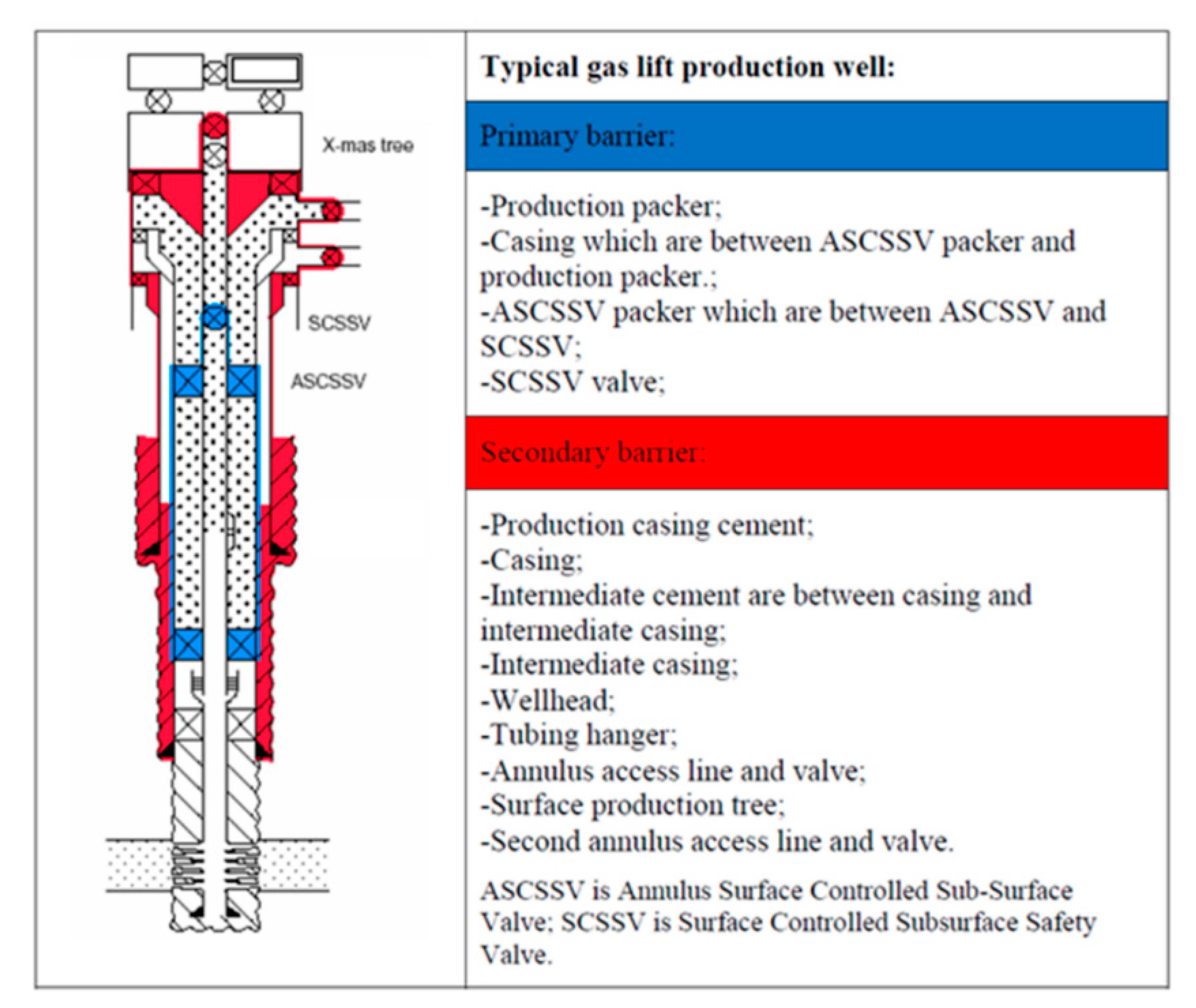
The Well Control System or the Blowout Prevention System on a drilling rig is the system that prevents the uncontrolled, catastrophic release of high-pressure fluids (oil, gas, or salt water) from subsurface formations. These uncontrolled releases of formation fluids are referred to as Blowouts. Due to the explosive nature of oil and gas, any spark on the surface can result in the ignition of the fluids and an explosion on the rig. An explosive blowout and the failure of the Well Control System were the causes of the Mocondo Well disaster that killed eleven of the rig crew on the Deep Water Horizon Rig on April 20, 2010 and resulted in 35,000 to 60,000 bbl/day of crude oil to spill into the Gulf of Mexico. We will discuss this later in the lesson.
The blowout preventers are the principal piece of equipment in the well control system and are operated hydraulically; pressurized fluids are used to operate pistons and cylinders to open or close the valves on the BOP. The Accumulators (Item 18 in Figure 9.02) are used to store pressurized, non-explosive gas and pressurized hydraulic fluid to run the hydraulics systems on the rig. The accumulators store enough compressed energy to operate the blowout preventers even if the Power System of the rig is not operating.
The blowout preventer is a large system of valves each of which is capable of isolating the subsurface of the well from the rig to provide control over the well. These valves are typically stacked as shown in the Figure 9.11 and sit below the rig floor on land wells or some offshore wells; or they may sit on the seabed on other offshore wells.
Figure 9.12 shows three type of valves (there are others) – an Annular Preventer, Blind Rams, and Shear Rams. The Annular preventer is the ring-shaped piece of equipment on the top of the BOP in Figure 9.11. As the name implies, the annular preventer is used to prevent flow through the annular space between the drill string or casing and the annular preventer. The annular preventer can also be used for non-cylindrical pipe, such as the kelly, or open hole. The annular preventer consists of a doughnut shaped bladder that when in the open position allows the drill pipe to rotate but in the closed position seals the annulus. Figure 9.13 provides a schematic of the annular preventer.
Schematics of the ram-type preventers: the blind rams, the shear rams, and the pipe rams (pipe rams are not shown in Figure 9.12) are shown in Figure 9.14.
control formation pore pressures to assure desired well control (apply hydrostatic and hydrodynamic pressures in excess of the formation pore pressures to prevent fluids from entering the wellbore);
In the first objective re-quoted above, if we can keep the pressure exerted by the drilling mud greater than the pore pressure, then we know that fluids will flow in the direction of the mud to the formation. This cannot always be achieved. For example, if we drill through a natural fracture or if our mud density is too great and we inadvertently fracture one formation, then we may lose large quantities of the drilling fluid into the fracture (Lost Circulation). In this situation, instead of having the full weight of the mud column exerting pressure on a second (porous and permeable) formation, we may only have a fraction of the oil column height exerting a lower pressure on that second formation.
In the second objective re-quoted above, if we deposit an impermeable Drill Cake (filter cake) across an otherwise porous and permeable formation, then for a slightly Underbalanced Pressure (drilling fluid pressure lower than the formation pressure) we have created a seal between the wellbore and the formation. Again, this is not a Failsafe System because at greater underbalanced pressures, the higher formation pressures may be able to displace the drill cake.
The two previously discussed methods are used to help prevent a kick from occurring, but as mentioned they are not always successful, and kicks may still occur. The causes of a kick include:
improper mud replacement during tripping: while tripping out of the hole mud volumes must be pumped into the wellbore at high enough rates to replace drill pipe being removed from the wellbore;
lost circulation: as discussed earlier if large volumes of drilling fluid enter the subsurface in (1) high permeability formations, natural fractures, or drilling-induced fractures, then the effect is a shortened height and weight of the mud column.
increase in the rate of flow of the drilling fluid returns at constant pump rates (primary indicator of a kick):The increased rate is caused by formation fluids entering the wellbore and is a strong indication of a kick. In addition, if it is a gas kick, due to the compressible nature of gas, as the gas bubble travels up-hole and hydrostatic pressures decrease, the volume of the bubble will increase due to expansion.
volume of mud in the mud pit increases when no additional drilling fluids are added to the mud system (primary indicator of a kick):For the same reasons as mentioned above, if the volume of mud in the mud pits increases when no additional fluids have intentionally added, then the increased volume is caused by formation fluids entering the wellbore and is a strong indication of a kick.
drilling fluids returns continue to flow when the mud pumps are turned off (primary indicator of a kick):Drilling fluid returns when the mud pumps are shut-off indicate that formation fluids are entering the wellbore and displacing the mud.
improper wellbore fill-up/volume-balance on trips (primary indicator of a kick):If the drill pipe is removed from the wellbore, then the change in volume in the mud pits should equal the volume of the drill pipe removed from the hole. An improper volume balance is a strong indicator of a kick.
pump pressure decrease and pump stroke increase (secondary indicator of a kick):If low density fluids are displacing heavier drilling fluid in the annulus, then this will cause the pump pressure to decrease (the annular side of the u-tube is lighter than the drill pipe side of the u-tube which contains the mud pump pressure gauge). The imbalance in the u-tube, just described, will cause the heavier drilling fluid in the drill pipe to fall due to gravity, causing the mud pump to increase the number of strokes to keep up with the pressure imbalance.
occurrence of a Drill Break or Bit Drop (secondary indicator of a kick):A Drill Break (sudden change in the rate-of-penetration) or Bit Drop (sudden increase in the drill bit depth) typically occur at a change in the lithology of the formation being drilled. In particular, a large bit drop may be an indication of drilling through a natural facture system. Both drill breaks and bit drops are normally recorded in the drilling records. When working on naturally fracture reservoirs, these drilling records may be useful for mapping natural fractures. I personally worked in a field where we had a 12 meter (~ 36 ft) bit drop in one well in the reservoir – think about it, you are drilling away at a certain rate-of-penetration and, all of a sudden, the bit drops 36 feet for no apparent reason. This was caused by drilling through a solution enhanced fracture which over geologic time formed a cavern in the reservoir (this occurred several years prior to my arrival, but it was in the drilling records).
reduction in the mud weight (secondary indicator of a kick):The Mud Man may observe a reduction or Cut in the mud density at the rig-site mud laboratory. This again may be an indication of a kick.
When a kick occurs, the Operating Company and Drilling Company always have well-specific plans in-place for all wells to ensure that any controllable kick does not turn into an uncontrollable blowout. I cannot go into the details of a well-specific procedures, but they will include some of the following features if a kick occurs during drilling operations:
Pick the drill bit off-bottom and Space Out (Spacing out refers to pulling the drill pipe out the hole so that the top connection – the thickest part of the drill string containing the threads and joints – is several feet above the rig floor. Spacing out ensures that the smaller diameter section of the drill string is inside the BOP, so that pipe rams can close and seat properly or blind rams or shear rams are opposite the smallest diameter section of steel. See Figure 9.15B)
Other procedures will be used if the kick occurs while tripping into or out of the well. The details of some aspects of this procedure such as hard or soft shut-ins and the circulation methods, The Driller’s Method and The Weight and Wait Method, will be discussed in detail in your later drilling classes. More importantly, for every well that you are involved with, there will always be Daily Safety Meetings that discuss the current status of the well and the important safety aspects of all drilling activities related to that day’s operations.
So, we have discussed the role of drilling fluid to exert pressure on porous and permeable formations and to coat them with an impermeable filter cake to help prevent kicks from occurring. We have also discussed the role of the blowout preventer and company procedures to control a kick once one occurs. So, how do blowouts happen?
Perhaps you remember the Macondo Blowout (Deep Water Horizon Rig) disaster. The name Macondo was the Prospect name (remember, we discussed prospects and well proposals in a previous lesson) while the Deep Water Horizon was the name of the rig. This was the largest oil spill in the Gulf of Mexico. When the disaster occurred, eleven members of the rig crew were killed by the explosion when the natural gas ignited.
After learning about offshore drilling rigs, drilling crews, components of the drilling rig, kicks, and blowouts, I would highly recommend watching the movie “Deep Water Horizon” and use your knowledge about oil and gas well drilling to identify some of the technical aspects of the film. Ask yourselves some technical questions:
Why were running Cement Bond Logs (CBL) – well logs showing the quality of the cement job –and pressure-testing the cement so important to averting this disaster?

HPHT well is defined as the well have bottom hole temperature exceeds 300oF and bottom hole pressure greater than 0.8 psi/ft. Nowadays, companies try to find petroleum in unconventional areas such as HPHT deep water, to decrease the gap between the demand and supply. Drilling of HPHT deep water wells involves high risk and cost; therefore, effective methods are required to solve these issues. Oil and gas industry offer advanced drilling technologies to reach HPHT deep water reservoir targets safely[1].
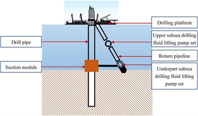
The margin between pore pressure and fracture pressure in HPHT deep water well is narrow, therefore accurate determination and optimization of well hydraulics is highly required. Managed Pressure Drilling (MPD) has been developed for overcoming the HPHT deep water well challenges. In MPD techniques, there is a method defined as Riser less drilling. The Riser less method uses two different annular fluid pressure gradients for well drilling. In the technique of Riser less drilling, the riser is completely filled with sea water and returned mud along with the cuttings is pumped by additional subsea mud pump to surface through small return line 6”,(Figure 1) [2].
There are pressure and temperature variations across wellbore during drilling by Riser less drilling technique; above seabed there is low temperature condition which will lead to increase in mud rheology, however below seabed there is opposite effect. Well hydraulics planning depends on how drilling fluid rheology is influenced by pressure and temperature effects inside wellbore; therefore, ignoring these effects in the well hydraulics calculations will give erroneous result[3].Accurate well hydraulics planning for HPHT wells is needed to avoid drilling problems such as kick and loss of circulation. This paper presents a new approach for accurate determination and optimization well hydraulics of MPD (Riser less drilling) under HPHT conditions. This work shows the comparison between well hydraulics calculated by constant fluid properties (i.e independent on pressure and temperature conditions) and well hydraulics calculated by taking into account the effect of pressure and temperature on fluid properties. This research also shows the effect of tool joint, cutting, annular eccentricity and drill string rotation pressure losses on well hydraulics of MPD.Theoretical Background
Temperature modelling, mud density and pressure modelling, plastic viscosity and yield point modelling and rheological hydraulic modelling are indeed important for accurate determination and optimization for well hydraulics of MPD under HPHT conditions.Drilling Fluid Temperature Modelling
Temperature modelling inside the wellbore is necessary for determining well hydraulics. Wellbore temperature has great impact on mud properties such as density, hydrostatic pressure, yield point and viscosity, therefore it will influence on the determination of pressure losses and Equivalent Circulating Density (ECD)[ 4].The Holmes and Swift model 5 assumes steady-state linear heat transfer between annulus fluid and the formation. The model is described in three steps[5].
Step 3: Calculation of temperature in drill pipe and annulus. For the temperature of the mud in the drill pipe and annulus (Equations 7, 8, 9, 10)[5].
Drilling fluid density is affected by temperature and pressure[6].The Hobe rock [7]Model assumes that drilling fluid density variations as a result of pressure and temperature changes occur due to liquid constituent’s volumetric behaviour such as water and/or oil.
Politte[8]studied rheological data for oil based mud and concluded that the plastic viscosity follows the base oil behaviour. Therefore, the plastic viscosity can be normalized with the base oil viscosity[9].The Politte[8]equation is described as follows.
Procedure of Politte correlation[8]can be used with any base oil. He established the following formula as a function of temperature and pressure for viscosity of base oil (Equation13) from analysis of diesel oil No. 2[8].
First two-parameter model is Power law model. The model is the most popular one in drilling engineering and it is used inside the simulator, Equation15[10].


 8613371530291