
disassemble mud pump prosess factory
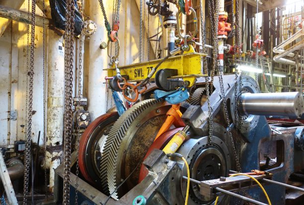
When it comes to the process of Mud pump repair, our expertise is second to none. Unlike smaller machine shops, We are pump repair specialists with expertise in repairing and rebuilding Mud pumps. We offer several level of rebuild options in order to make your Mud pump repair is as efficient and as economical as possible. We can manufacture many of the required components in-house for a Mud pump repair and or Mud pump rebuild as well.
You can trust the knowledge and expertise of your Mud pump repair in our hands. We have decades of qualified experience in the troubleshooting of your Mud pump repair, view our
We know the ins and outs of what made the Mud gearbox to fail, from the erosion that happens, to wear and tear of seals, it’s a common thing. That’s why trusting your Mud pump repair in our shop can only bring life to your Mud.
It’s not uncommon for other machine shops just trying to figure it out. Not here. We don’t have to figure out what happened to your Mud pump, again we have years and years of experience with Mud pumps and the Mud pump repair process. Although sometimes the Mud pump rebuild is a little bit different, we can ensure you that your Mud pump will be restored. It’s not uncommon for the Mud pump repair to suddenly turn into a process of rebuilding the Mud pump due to a further analysis of the breakdown in our shop.
We don’t take a first option of a rebuild due to it’s expense, because sometimes that can become a re-manufacturing process especially if the pump is very aged, but in the end, if a rebuild is needed for any type of re-manufacturing needs, you can count on MER to get the job done, that’s why we have a full facility dedicated to re-manufacturing these types of equipment to ensure the proper repair of your Mud pump. Nevertheless, we will let you know in what category it falls in before we even start the process of the Mud pump repair or the Mud pump rebuild.

METHOD OF DISASSEMBLING PUMP PISTON FROM PISTON ROD Filed Feb. 15, 1956 2 Sheets-Sheet l mmvron. JOHN HART WILSON J. H. WILSON Oct. 16, 1962 METHOD OF DISASSEMBLING PUMP PISTON FROM PISTON ROD Filed Feb. 15, 1956 2 Sheets-Sheet 2 John Hart PVils"ozz [NI ENTOR BY WnEw, Cola, Gemdk whinTsw 1 V/m I ll:
A7 TORNEYS" atent fiiice 3,058,207 Patented Oct. 16, 1962 3,058,267 METHOD OF DISASSEMBLING PUMP PISTON FROM PISTON ROD John Hart Wilson, Wilson Manufacturing Co., P.O. Box 1031, Wichita Falls, Tex. Filed Feb. 15, 1956, Ser. No. 565,686 1 Claim. (Cl. 29--427) This invention relates to improvements in pump piston pullers for reciprocating pumps and more particularly to pump piston pullers wherein the pump piston is removed from the piston rod by the power of the pump acting on the piston rod thereof when the piston puller is connected to the piston. The patent to John Hart Wilson, No. 2,249,- 802, Slush Pumps, issued July 22, 1941, discloses a power driven pump having a reciprocating piston rod and piston, the structure of which lends itself for use with the present tool.
Various piston pullers have been proposed heretofore, but these, for the most part, require a screw jack, hydraulic jack or other power means to operate the pump piston puller.
The present device is so constructed that pump pistons may be readily removed from the piston rod of the pump by the action of the piston rod of the pump on the pump piston, when the pump piston puller is attached to the pump piston, so sufficient power is transmitted from the piston rod to the pump piston to speedily and positively remove the pump piston therefrom, without manual effort and in a minimum of time.
An object of this invention is to provide a pump piston puller which may be readily attached to a pump piston, while the pump piston is within the liner within the pump, in such manner that the piston rod of the pump will be moved by the power of the pump to withdraw the piston rod therefrom, which rod is usually tightly fitted within the pump piston.
FIG. 1 is a longitudinal, sectional view through a pump cylinder, cylinder liner, and pump piston assembly, with the pump piston remover shown connected to the pump piston, and with portions thereof shown in section, and other parts shown in elevation, to illustrate the details of construction;
With more detailed reference to the drawing, FIG. 3 shows a longitudinal sectional view through a conventional slush pump or mud pump P, which has a crank C on the crank shaft S, which crank shaft is journaled in the housing of pump P. The crank shaft S is driven by a sprocket and chain drive, generally designated at D. A connecting rod R is pivotally connected to cross-head H, which cross-head has a pony rod Y extending outward therefrom, to which the piston rod 4a is connected. The piston rod 4a has a piston a mounted thereon near the outer end thereof. which piston 10a is fitted within liner 2a which is fitted in cylinder in. Upon the turning of the crank shaft S, by sprocket and chain drive D, the connecting rod 4a moves back and forth within liner 2a, in a manner well known in the art of reciprocating pumps, and as disclosed in the above-mentioned Patent No. 2,249,802. While the pump shown in FIG. 3 shows the piston 10a to have a straight bore therein to receive piston rod 4a, this is indicative of the manner in which pistons are used in pumps, such as disclosed in Patent No. 2,249,802. The piston rod and piston are replaceable by piston rod 4 and piston 10, as shown in FIG. 1, as any pump of this character which is equipped with the piston rod 4 and piston 10 will enable use of the pump piston puller of the present invention. Numeral 1 designates generally a pump cylinder in which a liner 2 is fitted. A piston rod 4 is shown extending into the liner 2, which piston rod has a tapered end portion 6 to complementarily engage a tapered bore 8 within piston 10. The body of the piston 10 has a neck 11, which neck 11 extends out and is threaded, as indicated at 12, to enable an interiorly threaded sleeve 14, of the pump piston puller designated generally at 15, to be screw threaded thereonto in the manner as shown in FIG. 1. The sleeve 14 is secured to a rod 16, which rod is threaded at its outer end. as designated at 18, to threadably receive a nut 20 thereon.
A lug 28 is welded, or otherwise secured, to an end of the cross bar assembly 22 so the lug will engage the upper side of cylinder 1, when the cross bar assembly is fitted in place and to support the outer end of the rod 16 of the pump piston puller before the final tightening of nut 20 on threaded portion 18 or rod 16.
Operation To remove the pump piston 10 from the connecting rod 4, after having removed the cylinder head of the pump, the sleeve 14 is threadably engaged with the threaded portion 12 of piston 10. Whereupon, the pump piston rod 16 is rotated by fitting a wrench on hexed head 30 thereof, so as to turn the rod 16 and sleeve 14 to threadably engage the threaded portion 12 of piston 10.
V Then cross bar assembly 22 is telescoped over elongated rod 16 until the inner face of the cross bar assembly 22 is in abutting relation with the outer face of the pump cylinder head ring 3, and with the lug 28 resting on top of the cylinder head ring 2, the cross bar assembly 22 is supported in this position until thrust bearing or Washer 26 and nut 20 are fitted onto the threaded rod to securely hold elongated rod 16 against inward longitudinal movement.
With the pump piston puller 15 in the position, as described above, and with the pump piston rod 4 at the extreme end of the outer stroke, the pump is started, whereupon the rod 4 is drawn inward and the pump piston 10 is retained against inward movement by a pump piston puller, designated generally at 15, which is attached to the threaded portion 12 of the pump piston body by sleeve 11.
With the driving power of the pump applied to the piston rod 4, a great pull can be exerted thereon to disengage the tapered portion 6 of the piston rod from the tapered bore 8 of the piston. After the piston rod 4 has been moved a sufficient distance away from the piston, the pump may be stopped and the piston readily re moved therefrom manually, but if the piston resists being pulled from the liner 2 manually, the nut 20 may be screwed on rod 16 so as to pull the piston outward until it loosens sufliciently to be readily removed.
In a method of removing a piston from a piston rod of a reciprocating pump on which it is frictionally engaged; the said piston being in place in said pump and reciprocatable longitudinally therein; comprising the steps of attachably securing to said piston a static element; of seating an end of said static element against the outer end of the pump in which said piston and piston rod are mounted; of operating the pump by power to reciprocate said piston rod in the direction to move said piston rod inward with respect to said piston while holding said piston statically so as to cause said piston rod to be automatically pulled from its friction fit on said piston rod; and of disengaging said piston from said static element.

The drilling industry has roots dating back to the Han Dynasty in China. Improvements in rig power and equipment design have allowed for many advances in the way crude oil and natural gas are extracted from the ground. Diesel/electric oil drilling rigs can now drill wells more than 4 miles in depth. Drilling fluid, also called drilling mud, is used to help transfer the dirt or drill cuttings from the action of the drilling bit back to the surface for disposal. Drill cuttings can vary in shape and size depending on the formation or design of the drill bit used in the process.
Watch the video below to see how the EDDY Pump outperforms traditional pumps when it comes to high solids and high viscosity materials commonly found on oil rigs.
The fluid is charged into high-pressure mud pumps which pump the drilling mud down the drill string and out through the bit nozzles cleaning the hole and lubricating the drill bit so the bit can cut efficiently through the formation. The bit is cooled by the fluid and moves up the space between the pipe and the hole which is called the annulus. The fluid imparts a thin, tough layer on the inside of the hole to protect against fluid loss which can cause differential sticking.
The fluid rises through the blowout preventers and down the flowline to the shale shakers. Shale shakers are equipped with fine screens that separate drill cutting particles as fine as 50-74 microns. Table salt is around 100 microns, so these are fine cuttings that are deposited into the half-round or cuttings catch tank. The drilling fluid is further cleaned with the hydro-cyclones and centrifuges and is pumped back to the mixing area of the mud tanks where the process repeats.
The drill cuttings contain a layer of drilling fluid on the surface of the cuttings. As the size of the drill cuttings gets smaller the surface area expands exponentially which can cause rheological property problems with the fluid. The fluid will dehydrate and may become too thick or viscous to pump so solids control and dilution are important to the entire drilling process.
One of the most expensive and troubling issues with drilling operations is the handling, processing, and circulation of drilling mud along with disposing of the unwanted drill cuttings. The drilling cuttings deposited in the half round tank and are typically removed with an excavator that must move the contents of the waste bin or roll-off box. The excavators are usually rented for this duty and the equipment charges can range from $200-300/day. Add in the cost for the day and night manpower and the real cost for a single excavator can be as much as $1800/day.
Offshore drilling rigs follow a similar process in which the mud is loaded into empty drums and held on the oil platform. When a certain number of filled drums is met, the drums are then loaded onto barges or vessels which take the drilling mud to the shore to unload and dispose of.
Oil field drilling operations produce a tremendous volume of drill cuttings that need both removal and management. In most cases, the site managers also need to separate the cuttings from the drilling fluids so they can reuse the fluids. Storing the cuttings provides a free source of stable fill material for finished wells, while other companies choose to send them off to specialty landfills. Regardless of the final destination or use for the cuttings, drilling and dredging operations must have the right high solids slurry pumps to move them for transport, storage, or on-site processing. Exploring the differences in the various drilling fluids, cutting complications, and processing options will reveal why the EDDY Pump is the best fit for the job.
The Eddy Pump is designed to move slurry with solid content as high as 70-80 % depending on the material. This is an ideal application for pumping drill cuttings. Drill cuttings from the primary shakers are typically 50% solids and 50% liquids. The Eddy Pump moves these fluids efficiently and because of the large volute chamber and the design of the geometric rotor, there is very little wear on the pump, ensuring long life and greatly reduced maintenance cost for the lifetime of the pump.
plumbed to sweep the bottom of the collection tank and the pump is recessed into a sump allowing for a relatively clean tank when the solids are removed. The Eddy Pump is sized to load a roll-off box in 10-12 minutes. The benefit is cuttings handling is quicker, easier, safer, and allows for pre-planning loading where the labor of the solids control technician is not monopolized by loading cuttings. Here, in the below image, we’re loading 4 waste roll-off bins which will allow the safe removal of cuttings without fear of the half-round catch tank running over.
Mud cleaning systems such as mud shaker pumps and bentonite slurry pumps move the material over screens and through dryers and centrifuges to retrieve even the finest bits of stone and silt. However, the pump operators must still get the raw slurry to the drill cuttings treatment area with a power main pump. Slurry pumps designed around the power of an Eddy current offer the best performance for transferring cuttings throughout a treatment system.
Options vary depending on whether the company plans to handle drill cuttings treatment on-site or transport the materials to a remote landfill or processing facility. If the plan is to deposit the cuttings in a landfill or a long-term storage container, it’s best to invest in a pump capable of depositing the material directly into transport vehicles. Most dredging operations rely on multiple expensive vacuum trucks, secondary pumps, and extra pieces of equipment.
Using an EDDY Pump will allow a project to eliminate the need for excavators/operators to load drill cuttings, substantially lowering both labor and heavy equipment costs. The EDDY Pump also allows a company to eliminate vacuum trucks once used for cleaning the mud system for displacing fluids. Since the pump transfers muds of all types at constant pressure and velocity throughout a system of practically any size, there’s little need for extra equipment for manual transfer or clean up on the dredge site.
The EDDY Pump can fill up a truck in only 10 minutes (compared to an hour) by using a mechanical means such as an excavator. For this reason, most companies can afford one piece of equipment that can replace half a dozen other units.
This application for the Eddy Pump has the potential to revolutionize the drilling industry. Moving the excavator out of the “back yard” (the area behind the rig from the living quarters) will make cuttings handling a breeze. Trucking can be easier scheduled during daylight hours saving on overtime and incidences of fatigued driving. Rig-site forklifts can move the roll-off boxes out of the staging area and into the pump loading area. The operator can save money on excavators rental, damages, and keep the technician operating the solids control equipment.
The EDDY Pump is ideal for drilling mud pump applications and can be connected directly onto the drilling rigs to pump the drilling mud at distances over a mile for disposal. This eliminates the need for costly vacuum trucks and also the manpower needed to mechanically move the drilling mud. The reasons why the EDDY Pump is capable of moving the drilling mud is due to the hydrodynamic principle that the pump creates, which is similar to the EDDY current of a tornado. This tornado motion allows for the higher viscosity and specific gravity pumping ability. This along with the large tolerance between the volute and the rotor allows for large objects like rock cuttings to pass through the pump without obstruction. The large tolerance of the EDDY Pump also enables the pump to last many times longer than centrifugal pumps without the need for extended downtime or replacement parts. The EDDY Pump is the lowest total life cycle pump on the market.

A mud pump is a piston driven pump design that can produce high-pressure operations to safely transfer high viscosity fluids over an extended depth. The mud pump has many applications in industrial service, but it has proven to be invaluable in many drilling operations. Let"s take a look at mud pumps and why they are such a good fit for the industries they serve.
A Mud pump is a reciprocal pump design utilizing a piston in a cylinder to transfer fluids under high pressure. A mud pump can generate up to 7,500 psi (52,000 kPa) during normal operations. Mud pumps are a positive displacement design.
Mud pumps are available in a variety of configurations and sizes. However, mud pumps tend to be one of two main types: the duplex and the triplex. The duplex mud pump features two pistons (or plungers) in constant action to move the fluid.
The triplex mud pump has all but replaced the duplex version in most applications, although you will still find the latter in use in some smaller countries. The triplex mud pump features a triple piston (plunger) design that is more efficient than the duplex design.
The latest designs of the mud pump are the quintuplex and hex versions. As the name suggests, these designs feature five or six pistons in a reciprocating design. Although not in widespread use as compared to the triplex design, these mud pumps spread the pumping action across the rotational cycle, creating less mud noise. This allows for better measurements and logging to take place while in operation.
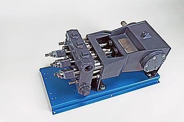
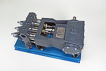
There are two main parts to a mud pump: the fluid end and the power end. The fluid end is where the actual pumping takes place. The components of the fluid end consist of valves, pistons (or plungers), and liners.
Since the fluid end is in constant contact with the material being pumped, most modern designs allow for quick replacement of worn components as needed. This dramatically extends the life of a unit without having to completely replace the pump.
The power end of a mud pump is responsible for taking the input power, typically through a driveshaft, and converting it into the reciprocating motion needed for the pistons. In most mud pump applications, the power end uses a crosshead crankshaft for this conversion.
Rotational power is supplied to the mud pump through an external power source. The power end of the pump converts this rotational energy through a crankshaft to a reciprocating motion that moves the pistons.
Due to the pressure and material being pumped, most mud pump applications can create a lot of vibration. To combat this, many mud pump applications incorporate pulsation dampeners. These are typically used on both suction and discharge sides of the pump.
In some cases, a positive displacement pump may pull the fluids at a pressure lower than its vapor pressure. When this happens, damaging cavitation can take place. In these cases, a charge pump might be required at the inlet side to maintain a positive pressure on the suction stream.
When selecting a mud pump, there are two main parameters to be used, pressure and displacement. Pressure is the net pumping pressure that the pump can safely provide. The requirement for pressure increases as the drilling depth and fluid (or slurry) viscosity increases.
Displacement is the volume of fluid that the pump can transfer within a given time period. In most applications, this is rated as discharged liters per minute.
Mud pumps are ideal wherever a lot of fluid needs to be pumped under high pressure. They are considered an essential part of most oil well drilling rigs. Mud pumps can deliver high concentration and high viscosity slurry in a stable flow, making them adaptable to many uses.
Mud pumps are an invaluable tool when high pressure and high viscosity fluids are needing to be transferred. Mader Electric, Inc. specializes in mud pump repair and installation, as well as pump training. Contact us to see how we can help with your pumping needs.
Elgin’s abrasion resistant slurry pumps are designed to better manage abrasive materials associated with pumping operations. Whether operated as a standalone pump or part of Elgin’s turn-key solutions, abrasion resistant slurry pumps improve performance and extends pump life versus traditional pumps.

American Mud Pumps LLC: warrants its products to be free from defects in material and/or workmanship under normal use and service for a period of one(1)year from the date of shipment. The liability for any defects shall be limited to the repair or replacement of such products, or at the option of American Mud Pumps LLC the refunding of purchase price. This warranty is expressly in lieu of all other warranties and representations, expressed or implied, and all other obligations or liabilities on the part of American Mud Pumps LLC, which shall not be liable for consequential damages for any breach of warranty."
American Mud Pumps LLC is a quality independent company. We are neither a licensee, nor affiliated with any other original equipment manufacturer (OEM) which may be named throughout. The manufacturers" names or trademarks used herein are solely for identification purposes and are not intended by American Mud Pumps LLC to cause confusion as to the source, sponsorship or quality of the parts provided by American Mud Pumps LLC. The OEMs named throughout this catalog do not sponsor, promote, warranty or endorse American Mud Pumps LLC products. Part number usage is for identification purposes only."
This mud pump will deliver the consistent flow of drilling fluid that is vital to HDD pipeline drilling projects. Suction inlet valve suspends charged flow during drill rod makeup and breakout process, keeping excess drilling fluid from escaping as drill pipes separate. The lubrication pump is driven off the auxiliary pad on the engine. It provides 55 psi (3.8 bar) of continuous crankshaft lubrication. The internal hydraulic reservoir has a capacity of 49 gal (185.5 L). Clutch with continuous duty throw-out bearing allows for longer pump disengagement during drill rod makeup/breakout....
A triplex piston pump produces up to 435.3 gpm (1647.8 L/min), providing a continuous flow of drilling fluid during drill operations. An electric centrifugal pump provides constant flow, keeping the pump running cool and leading to a longer life for both pistons and liners. Remote pendant control allows operator to mount controls where it makes sense for them. The remote pendant control monitors mud rate and eliminates the need for stroke counter. The integrated liner wash tank eliminates the need for additional water containers or electricity when running the pump. An engine-mounted air...


 8613371530291