
diy drywall mud pump supplier

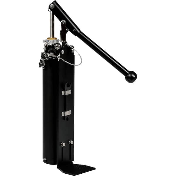
Drywall Master Taping Tools Extended Quick Clean Mud Pump is used to fill automatic taping tools with mud compound. DrywallMaster pump uses gooseneck (sold separately) to fill automatic taper. Box filler (also sold separately) attaches to pump to fill all other finishing tools. Industry exclusive double o-ring head seal on Drywall Master mud pump keeps mud from seeping between head and pump tube for better seal and easier separating, cleaning or maintenance.
Unique dual o-ring head seal keeps mud from getting between head casting and pump tube. This makes pump easier to separate for cleaning or maintenance.
The Loading Pump, with appropriate accessories (Gooseneck and/or Filler Adapter), is used to fill the following tools: Automatic Taper, Corner Applicator/Corner Box, Nail Spotter, and Flat Box. Attach the Gooseneck to fill the Automatic Taper. Attach the Filler Adapter to fill the Nail Spotter, Corner Applicator, and Flat Box. Simply hang the tube of Loading Pump into a bucket of mud, leaving the leg of the Pump on the floor. Attach the appropriate accessory to the pump. Prime the Pump by pumping the handle a couple of times. Now you should be ready to fill your tool.

Afghanistan, Albania, Algeria, Andorra, Angola, Anguilla, Antigua and Barbuda, Argentina, Armenia, Aruba, Australia, Austria, Azerbaijan Republic, Bahamas, Bahrain, Bangladesh, Belgium, Belize, Benin, Bermuda, Bhutan, Bolivia, Bosnia and Herzegovina, Botswana, Brazil, Brunei Darussalam, Bulgaria, Burkina Faso, Burundi, Cambodia, Cameroon, Canada, Cape Verde Islands, Cayman Islands, Central African Republic, Chad, Chile, Colombia, Costa Rica, Cyprus, Czech Republic, Côte d"Ivoire (Ivory Coast), Democratic Republic of the Congo, Denmark, Djibouti, Dominican Republic, Ecuador, Egypt, El Salvador, Equatorial Guinea, Eritrea, Estonia, Ethiopia, Fiji, Finland, France, Gabon Republic, Gambia, Georgia, Germany, Ghana, Gibraltar, Greece, Greenland, Grenada, Guatemala, Guinea, Guinea-Bissau, Guyana, Haiti, Honduras, Hungary, Iceland, India, Indonesia, Iraq, Ireland, Israel, Italy, Jamaica, Japan, Jordan, Kazakhstan, Kenya, Kiribati, Kuwait, Kyrgyzstan, Laos, Latvia, Lebanon, Lesotho, Liberia, Liechtenstein, Lithuania, Luxembourg, Macau, Macedonia, Madagascar, Malawi, Malaysia, Maldives, Mali, Malta, Mauritania, Mauritius, Mexico, Moldova, Monaco, Mongolia, Montenegro, Montserrat, Morocco, Mozambique, Namibia, Nauru, Nepal, Netherlands, New Zealand, Nicaragua, Niger, Nigeria, Norway, Oman, Pakistan, Panama, Papua New Guinea, Paraguay, Peru, Philippines, Poland, Portugal, Qatar, Republic of Croatia, Republic of the Congo, Romania, Rwanda, Saint Helena, Saint Kitts-Nevis, Saint Lucia, Saint Pierre and Miquelon, Saint Vincent and the Grenadines, San Marino, Saudi Arabia, Senegal, Serbia, Seychelles, Sierra Leone, Singapore, Slovakia, Slovenia, Solomon Islands, South Africa, South Korea, Spain, Sri Lanka, Suriname, Swaziland, Sweden, Switzerland, Taiwan, Tajikistan, Tanzania, Thailand, Togo, Tonga, Trinidad and Tobago, Tunisia, Turkey, Turkmenistan, Turks and Caicos Islands, Uganda, United Arab Emirates, United Kingdom, United States, Uzbekistan, Vanuatu, Vatican City State, Vietnam, Wallis and Futuna, Western Samoa, Yemen, Zambia, Zimbabwe

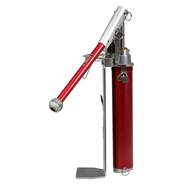
When it comes to drywall tools, a compound pump is a workhorse that keeps all drywall finishing and taping tools moving. So, what makes a good drywall pump? Here"s LEVEL5 founder Scott Murray with an overview (or read on to learn more).
LEVEL5’s drywall compound pump has been made to meet finisher’s demand forreliability, affordability and workability. This beast of a taping tool is built to withstand years of heavy use.
We specifically chose to construct our pump out of billet aluminum (instead of less-durable cast aluminum) to give it as rock-solid a build as possible. Using advanced anodization technology, we’ve designed our compound pump to feature outstanding corrosion resistance. This same anodization also makes it more resistant to everyday wear and tear.
The body of the LEVEL5 mud pump is longer to make it compatible with more bucket sizes. Its composite cup seal is designed to be longer lasting than traditional rubber seals used by other major brands. To effectively minimize pump priming we"ve added a precision-molded flapper valve and seal assembly.
The build quality, attention to innovation and 7-Year warranty make this pumpunrivaled in terms of value to the finisher. Combine these with the fact that LEVEL5’s compound pump is among the most affordable on the market and it’s easy to see why our taping tools are setting the industry standard for finishers far and wide.
This drywall mud pump has been built to last, comes ready to go right out of the box and is innovated to fit any drywall finisher’s workflow. We’ve gone above and beyond to make our pump the most workable on the market.
No doubt the ability to clean, repair and maintain your drywall tools plays a big role in which taping tools you choose to invest in. We’ve built the LEVEL5 drywall pump to be extremely easy to take apart and rebuild thanks to heavy-duty grenade pins and easy-release latches on its tube and handle.
To help make tool maintenance second nature, we’ve created a built-in wrench mount to ensure quick access to your wrench that comes included with every purchase of a LEVEL5 drywall compound pump. Once you’ve mastered how to take apart and maintain your pump, you’ll never be without one on the job.
To help ensure that your LEVEL5 mud pump is ready to go right out of the box, we include afreebox filler valvewith every purchase. This filler valve is quickly and easily swapped out with our gooseneck so that you can go from filling flat boxes to filling your automatic taper seamlessly.
It’s important to note that the LEVEL5 drywall compound pump is not compatible with goosenecks from other manufacturers due to the pump’s extended length. The LEVEL5 Gooseneck (4-714) has been specifically designed for use with this pump.
Here at LEVEL5 we know you want a pump that’s dependable, affordable and easy to maintain. Our pump’s innovative design features, premium build materials and 7-Year warranty provide unsurpassed value to the finisher.
Automatic Taping Tools are more powerful and efficient than traditional hand tools. Whether you"re a drywall professional, remodeler, or DIY, automatic taping tools achieve better results in half the time. Drywall Loading Pumps (mud pumps) are compound pumps that use Gooseneck and Box Fillers Adaptors to fill drywall taping and finishing tools. All-Wall offers the largest selection of Loading Pumps from top brands such as TapeTech, Columbia, Asgard, Graco, and Drywall Master.

Drywall Tools for every application, and all phases of drywall construction. Welcome to WallTools.com - the web"s biggest and best store of drywall tools and supplies. We stock the largest inventory of drywall tools, replacement parts and sundries and other specialty tools for the walls and ceilings trades. Our great prices and excellent customer service make Wall Tools your one stop shop for taping tools, sanding tools, drywall finishing, texturing, stilts and beyond. Our drywall superstore ships worldwide from our central warehouse, and partner warehouses throughout the United States and Canada.

{"links":[{"url":"https://www.graco.com/us/en/contractor/solutions/articles/how-to-mix-drywall-mud-for-texture-spraying.html", "anchor_text":"How to Mix Drywall Mud for Texture Spraying"},{"url":"https://www.graco.com/us/en/contractor/products/drywall-finishing-interior-texture/interior-texture-sprayers.html", "anchor_text":"Interior Texture Sprayers"},{"url":"https://www.graco.com/us/en/contractor/products/drywall-finishing-interior-texture/drywall-finishing-tools-accessories.html", "anchor_text":"Drywall Finishing Tools & Accessories"}]}
{"links":[{"url":"https://www.graco.com/us/en/contractor/solutions/articles/how-to-mix-drywall-mud-for-texture-spraying.html", "anchor_text":"How to Mix Drywall Mud for Texture Spraying"},{"url":"https://www.graco.com/us/en/contractor/products/drywall-finishing-interior-texture/interior-texture-sprayers.html", "anchor_text":"Interior Texture Sprayers"},{"url":"https://www.graco.com/us/en/contractor/products/drywall-finishing-interior-texture/drywall-finishing-tools-accessories.html", "anchor_text":"Drywall Finishing Tools & Accessories"}]}

What"s equally as important as your automatic taping and finishing tools? You need a reliable mud pump. The drywall compound pump, or mud pump, is necessary to quickly fill your automatic tools such as a flat box or automatic taping tool, and keep the job moving with minimal delay. Without a reliable pump, you’ll be spending more time fiddling with a pump that is difficult to clean, or worse, resorting to hand-filling your tools, which is time consuming, and counter productive.
No pump = no tools, so you need a workhorse that will withstand a lot, and get through your workday, every time. TheLevel5 Drywall Compound Pumpis constructed of billet aluminum, making it much stronger, and more durable than your typical cast aluminum construction.
Another important quality is resistance to corrosion. Tools built of poor quality and materials are prone to rust and corrosion. The anodization on the Level5 Drywall compound pump makes it highly resistant to corrosion, as well as wear and tear!
A good seal is important too! Typically for compound pumps, a rubber seal is used, but the problem with rubber is that it will slowly deteriorate, and before you know it, you’re leaking all over the place. The Level5 Drywall Compound Pump uses a composite urethane cup seal, which provides much longer wear life vs. the traditional rubber seals.
Working with mud can be messy, and when you’re on the job, it"s important to be able to easily clean and maintain your compound pump. You should not be spending any extra time fiddling with small screws or components to clean your pump, or to switch valves.
That’s why the Level5 Compound pump has easy clean features, like grenade pins and easy-release latches on its tube and handle. It also comes with a wrench, and a built-in wrench mount so that you are always prepared to switch from gooseneck to box-filler valve, or make a quick adjustment with ease.
Theoretically, yes you can, but it"s a slow process, and at which point you may be better off hand finishing, as you will impede the speed of the work. The combination of your automatic tools and your mud pump will pay for itself fairly quickly by the speed and quality job that you can achieve.
We think the Level5 Drywall Compound Pump is the best drywall mud pump on the market, and truly the underestimated workhorse in the arsenal of any professional drywall finisher. LEVEL5’s drywall compound pump has been made to meet finisher’s demand for reliability, affordability and workability. This beast of a taping tool is built to withstand years of heavy use. In fact, the Level5 compound pump has been tested for over 250,000 cycles without the need or repair, or replacement parts.
If you’re interested in purchasing a compound pump, you can find more information here. And as always, feel free to email, or give us a call and we’d be happy to provide more information!

“Mudding,” the process of applying multiple thin coats of drywall compound to the joints and screw indentations in newly hung drywall, sounds messy, and it is. When done correctly, the result is a wall so flat that you cannot spot the seams.
While professional drywall tapers make mudding look easy, do-it-yourselfers find that it takes practice, skill, and—of course—the right gear (in this case, the mud itself and the tape that prevents cracks from appearing in the seams). This guide to how to mud drywall outlines the materials required for the job, and walks DIYers through the process step by step.
There are two main types of drywall mud: premixed and powdered. There are variations on each type, too, which can make it tough to choose the right product for your job. Here’s the lowdown on the types of drywall mud you might find at the home improvement store:
Premixed joint compound is just that: The mud has already been mixed with water to a smooth consistency and is ready to be applied. Within this category, you’ll find all-purpose mud, topping mud, and lightweight all-purpose mud.All-purpose mud goes on smoothly and usually begins to harden in a couple of hours, depending on the temperature and humidity in the room. It’s suitable for all mudding applications, and is the best drywall mud for beginners.
Topping mudis used as a final top coating. It dries to a bright white and is easy to sand, making it a good choice for walls that will be painted a light color. Topping mud has fewer adhesion properties than all-purpose mud, so it’s not suitable for first and second coats.
Lightweight all-purpose mud also dries to a lighter hue, which makes it suitable for walls that will be painted a light color. Some pros use all-purpose mud for the first mudding application and then switch to lightweight all-purpose mud for the second and third applications.
Powdered drywall mud, also called “setting mud” or “hot mud,” contains chemicals that hasten hardening time when water is added to the powder. This type of mud tends to shrink less than all-purpose premixed mud, but it hardens very quickly. Quick-setting mud works well for pre-filling large gaps in walls, or smoothing over crushed drywall corners before starting the actual mudding process.Timed drywall mud: Setting mud is labeled by the maximum amount of time you have to work with it before it hardens. You can choose from 5-minute mud, 20-minute mud, or longer-hardening times, depending on your needs. If you use setting mud, mix only as much as you need, and wash your tools frequently as you work.
Easy-to-sand setting mud: The chemicals in some types of hot mud harden into rock-like ridges on your walls, and you can spend hours trying to sand them smooth. Avoid this by choosing an easy-to-sand variety.
During the mudding process, tape acts as a bond to keep the finished wall from developing cracks along the drywall seams. The different types of tape are paper, mesh, and preformed—and all three have their pros and cons.Paper tapeis used almost exclusively by the pros because it’s very thin, which helps create imperceptibly smooth drywall joints. Paper tape comes with a crease down the center that allows you to bend it along the crease to form sharp wall corners. It takes practice, however, to correctly bed paper tape in the first coating of wet mud without creating bubbles underneath.
Mesh tapeis made from fiberglass threads in an open-weave pattern and comes with adhesive on the backside. While it’s fairly simple to position mesh tape over a dry joint and then apply your first coat of mud on top, mesh tape is thicker than paper tape and can result in more noticeable joints when the wall is painted.
Primed with an understanding of mudding materials, it’s time to familiarize yourself with the process as outlined here. Because paper tape offers the most professional results, we’ll detail how to mud sheetrock using paper tape. If you’re using mesh tape, you’ll find some tips below that will help you use it correctly.
Cover the floor with a canvas drop cloth (plastic drop cloths can become dangerously slick) and don goggles and old clothing. Mudding is a messy process, and splatters can sting if they get in your eyes.
Remove the lid from the bucket of premixed mud. If using powdered setting mud, mix as recommended by the manufacturer, beating until smooth with a heavy duty drill fitted with a paddle bit.
Drywall panels come with slight bevels on both of their long sides. When the bevels are fitted together, they form a small indentation, about 2 inches wide, along the joints. Use the 6-inch taping knife to smooth and work the mud evenly into the joint, filling the entire indentation and wiping away excess mud.
Cut and fit a piece of paper tape over the joint while the mud is still wet for a process called “bedding.” Use the 6-inch taping knife to gently smooth the paper onto the wet mud, working out bubbles as you go. Wipe away excess mud with the knife.
With the 6-inch knife, apply a thin coat of mud to both sides of an inside corner, making sure to work it all the way into the center. Cut, fold, and fit a strip of pre-creased paper tape in the corner over the wet mud. Smooth the paper tape carefully in the wet mud, using either a 6-inch taping knife or an inside-corner taping tool that features a preformed 90-degree shape for easy bedding. Use light stroking movements to bed the tape without dislodging it from the corner. Wipe excess mud from the walls.
If using preformed tape corners, attach them as recommended by the manufacturer, and then smooth mud over the corners, using long vertical strokes on both sides to form a sharp, uniform corner.
You can avoid butt joints, which occur when un-tapered ends of a drywall panel are fitted together, by using sheets of drywall that span the entire room. But if dealing with ends that have no beveled indentations, it’s more challenging to get a smooth finish. Mud them as you did the beveled joints, taking care to use only as much mud as necessary to fill the joint and bed the tape.
Let all the mud dry before applying the next coat. Apply a second coat of mud to the screw indentations, beveled joints, and inside and outside corners in the same order as the first coat—only this time, use only mud. No need to add more tape! Just apply a thin layer of mud and wipe off all excess.
To do a second coat for butt joints, take the 10-inch taping knife, apply two swaths of mud, approximately 8 inches wide, along both sides of the first joint coat, but not on top of the original joint. This imperceptibly builds up the wall depth over a wider area to reduce the appearance of a bulky butt-joint seam. Feather out the edges of the swaths well with the knife for a smooth look.
Apply a third very thin coat of mud after the second coat dries. Use the 10-inch knife for all screw indentations, seams, and corners. The wider knife allows you to feather out the edges of the mud to a razor-thin application. Follow the same procedure for beveled joints and corners as before. On butt joints, apply a thin coat of mud over the previous swaths and the original mud joint. It’s not unusual for the mud swath on butt joints to be 2 feet wide or wider.
When the mud dries, apply one last thin coat only over the butt joints. Feather out the edges very well and let the mud dry. Before moving onto the final step, an important question to ask is, “How long does drywall mud take to dry?” Approximately 24 hours is the answer for most types of drywall mud, but refer to your product’s label for specifics on drying time.
Don your respirator mask and goggles prior to sanding. Use a drywall pole sander or, if it’s important to keep airborne dust at a minimum, rent a power drywall sander from your local construction rental store. Sand all joints and nail indentations until the wall is perfectly smooth. Now you’re ready to paint or wallpaper!
Unlike paper tape that requires bedding in wet mud, self-adhesive mesh tape is applied over seams and then, when mud is applied, an adequate amount seeps through the mesh into the seam beneath. The order of taping is the same: Do screw indentations and beveled joints first, inside and outside corners next, and butt joints last. If you use mesh tape on flat joints, note that it’s not suitable for corners. Use pre-creased paper tape for inside corners and preformed tape for outside corners.

This invention relates to drywall taping and texture systems, and, in particular embodiments, to a drywall taping and texture system using an automatic pneumatic bladder pump with a flip/flop logic mechanism, that may be controlled remotely by an operator.
Traditionally, in gypsum wallboard or “drywall” panel installation, sheets of drywall are nailed or screwed in place. Seams between the drywall sheets must be taped over, and the nail or screw heads must be coated with paper tape and mastic material to form a continuous wall surface. Tape and mastic material must also be applied to inside corners to form a complete wall system. The task of applying drywall tape and mastic drywall mud is generally laborious, tedious, and messy. Although inventions have made the task easier, improvement is still needed. One currently available drywall taping tool is the pedestrian mud pan and drywall knife.
With a mud pan and drywall knife, a workman manually applies drywall tape and mud. First, the workman removes a scoop of mud from a bulk container in a mud supply area and places it in the mud pan. This action is repeated until the pan is full. The workman then walks from the mud supply area to the seam that he wishes to tape. The workman then scoops a quantity of mud onto the knife, turns the knife blade towards the wall, and with a series of wiping motions, coats the seam with mud more or less uniformly. After precutting the tape, the workman lays paper tape over the seam and presses it into the mud to achieve tape attachment. He then glides the knife over the tape, forcing mud and air out from behind the tape, and begins to smooth the surface. A first coat of mud is applied to the drywall tape either at the time that the tape is applied or later, depending on the workman"s technique.
After a period of drying, another coat of mud is applied to the tape and dressed with a drywall knife, thus covering the seam with a wider coat of mud. The same steps of walking to the mud supply area, scooping out mud until the pan is full, and then walking back to the work area are repeated.
After a second period of drying, most inexperienced workmen sand the seams before applying a final coat of mud. The final coat of mud requires further walking between the mud supply and the work areas and further scooping and filling of the mud pan as before.
Complicating the situation are inside corner seams. Most occasional drywall workmen find inside corner seams the hardest and most time consuming to tape and coat of any seam. There are special knives that have a ninety degree bend to help dress these difficult seams.
To overcome the drawbacks of pedestrian drywall tape application and finishing tools such as the mud pan and drywall knife, a professional “automatic” drywall taping system has been developed by Ames Tool Company (Ames), for example, that includes a manual, lever action, fluid mud pump that fills assorted mud applicator tools from a 5 gallon bucket filled with slightly thinned drywall mud. A hand lever on the manual pump is pumped up and down to transfer drywall mud out of the bucket directly into a mud applicator tool. The mud is squirted into a slot in some tools and into other tools through a special fitting.
However, this system still requires walking between the mud supply station and the current work areas, thus wasting time and energy. Only about ninety feet of tape can be applied with the Ames taper tool before a mud refilling is required, while each roll of paper tape is about 500 feet. Only about three to four vertical seams, where each seam is about eight feet long, can be filled with the Ames box tools before more mud is required. Thus, a day"s work may require hundreds of trips for mud refills between the mud supply and work areas with the Ames drywall taping system.
Additionally, each of the tools in the Ames system takes some toll upon the user"s energy. The Ames taper tool is powered by the user forcing a wheel to turn as it contacts the wall at the end of the tool. The Ames box tool requires the operator to forcefully wipe a heavy box of mud held out on an extended handle. Each of the Ames tools mechanically disgorges drywall mud as the result of strenuous human labor. Many tasks in drywall taping with Ames type systems are thus prone to cause repetitive stress injury.
Furthermore, Ames tools require both a reservoir that holds one shot of mud and a mechanical device to manually exude the shot of mud out of the tool and onto a drywall surface. The Ames system is expensive, heavy, and manually actuated. Ames-type tools are now manufactured by several companies using similar designs that are based upon many complicated and varied machined metal parts and are thus expensive to manufacture. Those tool designs do not lend themselves to mass production of most of the parts (e.g., in plastic) for the “do it yourself” market. There is also a learning curve with Ames-type tools due to the skill required to properly operate them. In addition, there is extensive tool cleaning required after each use to ensure proper operation, and tool failures are common in the Ames system due to dried mud and mechanical failures.
The stator tube pump is well known to the drywall industry, particularly with commercial drywall texture sprayers. This type of pump has a hollow threaded internal rubber sleeve encompassing a softly threaded extended rod. As the rod is turned, fluid drywall material is forced to exit the pump under pressure into a material hose. However, the stator pump requires an electric motor or gas engine to operate. As such, it is expensive to build and costly to buy and operate. The stator pump is also very inefficient due to tremendous friction, so a large power source is required. Therefore, fluid material delivery systems using a stator pump for drywall work are an expensive way to go, with a market limited to professionals.
A second approach to spraying drywall textures is a hopper device with a gun and compressed air, which atomizes the material. This device is less expensive than pump units. However, it must be held overhead in the case of ceiling texturing, thus making its use very messy and tiring due to the stress of holding a heavy hopper full of texture overhead for extended periods. Presently, a gun on a hose is by far the preferred tool for texture application; however, such a device is currently too expensive for “do-it-yourself”, non-professional users.
An ideal system would be one in which the automatic tape functions of the Ames System are combined with the preferred spray functions of a material pump with a gun on a hose in such a way as to provide for an inexpensive solution for “do it your self” users. In such a system, the disadvantage in existing systems of carrying drywall mud back and forth will be reduced since the material is delivered by hose directly to the wall.
Examples of such a drywall taping and texture system are described in U.S. Pat. No. 6,299,686. In various embodiments discussed therein, the system includes various interchangeable tools that connect to a pump. A pump residing in a housing forces fluid drywall material through a material line. A control line hose also runs from the pump to the various tools.
The tools may include a button or trigger, allowing the user to remotely control the function of the pump by covering or uncovering an air release hole on the tool that is inter-connected to the control line to the pump. The control line outlet to the atmosphere is “normally open” at the distal, tool end. To close the control line, a plug is inserted into the air release hole to the atmosphere. Thus, opening the control line to the atmosphere releases air and resets the pump, whereas closing the control line starts the pumping action.
Additional air release mechanisms may be also be included in the pump housing itself, such as a pneumatic automatic flip flop logic switching system. This function may be performed in several ways. For example, in various embodiments of the invention of U.S. Pat. No. 6,299,686, this may be achieved electronically, with sensors and an electrical solenoid pneumatic valve, and/or mechanically, with a two-stage pressure relief valve. Both of these approaches provide for a less-expensive way of building and operating a bladder pump control than is available in previous mud pumping systems. In addition, in both cases, the device may be remotely controlled by an operator and run on a small, inexpensive air compressor of ¼ horsepower. Still, improvements may be made in the bladder pump and pneumatic system.
FIG. 3ais a perspective view of the interior parts of the pump shown in FIG. 1. FIG. 3bis a partial cross-sectional view of the interior of the pump shown in FIG. 1.
FIGS. 4aand 4bare partial cross-sectional views of the interior of the pump illustrating the pump in action. FIG. 4ashows the pump during intake of drywall material, and FIG. 4bshows the pump during exhaust of drywall material.
FIG. 5ais a side, cross-sectional view of a pump cap in accordance with an embodiment of the present invention. FIG. 5bis a top plan view of the pump cap, and FIG. 5cis a perspective view of the pump cap.
FIGS. 9a-9care views of an electrical version of the pump in accordance with an alternative embodiment of the present invention. FIG. 9ais a partial cross-sectional view of the interior of the pump. FIG. 9bis an exploded perspective view of a solenoid module for controlling the electrical version of the pump. FIG. 9cis an exploded, partial cross-sectional view of an inflation sensor for electronically sensing the condition of the bladder.
FIGS. 18a-18care views of adapter parts that allow use of the pump with Ames Tool Company"s tools in accordance with an embodiment of the present invention. FIG. 18ashows perspective and top plan views of an Ames adapter button. FIG. 18bis a perspective view of an Ames adapter gooseneck. FIG. 18cshows perspective and top plan views of an Ames adapter box filler.
FIGS. 24aand 24bare partial cross-sectional views of the interior of the pump depicted in FIG. 23, illustrating the pump in action. FIG. 24ashows the pump during exhaust of drywall material, and FIG. 24bshows the pump during intake of drywall material.
FIG. 25 is a perspective exploded view of a bladder pump with pneumatic pressure relief valve in accordance with the pump depicted in FIGS. 23 and 24.
FIG. 26ais a perspective view of the interior valve core assembly parts of a pump in accordance with an embodiment of the present invention. FIG. 26bis a partial cross-sectional view of the parts of this same embodiment.
FIG. 27ais the pump at rest, 27bis the pump with bladder filling, FIG. 27cis at valve opening, FIG. 27dis at bladder discharge, FIG. 27eis at valve closing.
FIG. 33 is a drawing of a bladder pump that uses electrical sensors and a magnet on the bladder to operate, with a schematic for the sensors, electro-pneumatic valve, latching relay and power input.
As shown in the drawings for purposes of illustration, the invention is embodied in a drywall taping and texture system and a pump. In preferred embodiments of the present invention, the drywall taping and texture system utilizes the pump and various tools connected to the pump for applying drywall tape, as well as mastic or fluid drywall mud and texture, to wall surfaces. However, it will be recognized that the disclosed bladder pump may be used in other systems and with other fluids, such as water, oil, gas, or the like.
FIG. 1 shows a perspective view of a drywall taping and texture system using a pump in accordance with an embodiment of the present invention. The drywall taping and texture system preferably includes a pump 1 immersed in a container of mastic or fluid drywall material 32. The pump 1 may be supported in the container by a bucket clip 22. Referring to FIGS. 1 and 2, the pump 1 is preferably contained within a generally cylindrical housing 29. The housing 29 may be a solid shell with strength to withstand changes in pressure within the pump 1 and to support various parts of the pump 1. The housing 29 may be manufactured from a plastic extrusion, such as simple plastic drain pipe, which is cut to an appropriate length and then drilled to hold fasteners, such as screws or the like, that penetrate into various parts of the pump 1. The pump 1 may include a cap 10 attached to the housing 29 using fasteners such as a pin or bolt, or the like. The pump cap 10 may further include an air stem fitting 13 for connecting to an air compressor 28; a material line fitting 26 for connecting a preferably plastic material line 14 to the pump 1; and a control line fitting 27 for connecting a preferably plastic control line 15 to the pump 1. The material line 14 and the control line 15 may attach at their respective distal ends through another material line fitting 26 and another control line fitting 27, respectively, to a variety of tools, such as a tape applicator tool 200, a wand tool 300, a mud knife tool 400, a mud bead tool 500, a wall texture spray tool 600, or an acoustic texture spray tool 700. The pump 1 may also be attached to a variety of tools manufactured by Ames Tool Company See FIG. 18a-cand the like, through adapter parts 800, 801, and 802.
In the embodiment illustrated in FIGS. 1 and 2, the pump 1 preferably has an air gauge 24 and a pressure relief valve 25. The pressure relief valve 25 is one type of air release valve or mechanism for releasing air from the drywall taping and texture system, as will be discussed below. In alternative embodiments, the air gauge 24 and the pressure relief valve 25 may be omitted.
As shown in FIGS. 3aand 3b, the bottom of the pump 1 may include an intake orifice 8 covered with a screen 9, which may be a barrier to particulate matter that might ruin the drywall finish or plug the tool attached to the pump 10. The mesh size of the screen 9 is preferably large enough to allow passage of acoustic ceiling grains, but small enough to stop larger particles. A user may change the screen 9 to screen mud or to spray acoustic. The screen 9 may be positioned over the intake orifice 8 so that all drywall material 32 passes through the screen 9 prior to entering the pump 1.
In preferred embodiments, the pump 1 has upper and lower valves for controlling the flow of the drywall material 32. In preferred embodiments, the valves are check valves that create a one-way flow of the drywall material 32 upward through the pump 1. In the embodiment illustrated in FIGS. 3a-4b, each valve includes a seat 3 or 7 having an orifice 17 or 8, respectively, through which the drywall material 32 flows, and a member 2 or 6 for controlling the flow of the drywall material 32 through the orifice 17 or 8, respectively. See FIG. 6a-d. However, in alternative embodiments, the valves may include other components, such as flappers or the like. The lower valve is preferably formed from a lower seat 7 and a lower member or ball 6. The upper valve may be similarly formed from an upper seat 3 and an upper member or ball 2. The upper and lower members may, in some embodiments, be formed as a plug, as illustratively depicted in FIGS. 23, 24, 26 and 27.
Referring to FIGS. 3a-4band 6a-6d, the upper and lower seats 3 and 7 may be generally shaped as a band or ring, configured to fit with the upper and lower balls 2 and 6, respectively. The seats 3 and 7 may be secured to the housing 29 using fasteners, such as screws, glue, bolts, or the like. Drywall material 32 may flow through an orifice 8 at about the center of the seat 3 or 7. The seat 3 or 7 may include a raised ring that contacts the ball 2 or 6, respectively, to separate granular elements from the drywall material 32 for proper sealing of the seat 3 or 7 and the ball 2 or 6, respectively. In alternative embodiments, the seat 3 or 7 may have other shapes.
In the illustrated embodiment, the lower seat 7 holds the screen 9. The intake orifice 8 in the lower seat 7 may alternatively have lateral vents so that pump 1 is not closed off by contact with the bottom of the container of drywall material 32.
Preferably, the upper and lower balls 2 and 6 are similar. The ball 2 or 6 is preferably made from a heavyweight material, such as iron, lead, or the like, and covered with a soft rubber or rubber-like material, such as elastromeric material or the like. The rubber or rubber-like material may help the ball 2 or 6 to seal with the seat 3 or 7 when stopping the backwards flow of the drywall material 32. By way of example, the ball 2 or 6 may be a solid material ball with a rubber coating, a rubber ball with a lead shot filling, or a spring-loaded ball. Most preferably, the ball 2 or 6 plugs the seat 3 or 7, respectively, when the drywall material 32 flows backwards, but does not stick in the orifice 17 or 8 of the seat 3 or 7, respectively. The upper and lower valves may thus create a one-way flow of the drywall material 32 upward through the pump 1.
The pump 1 may include a bladder 5 mounted within the housing 29 between the upper and lower valves. Referring to FIGS. 3a-4band 7, the bladder 5 may be made from a resilient, rubber or rubber-like material, such as elastomeric material or the like, with a diameter smaller than the diameter of a material chamber 4 of the pump 1. When inflated, the bladder 5 could be larger than the material chamber 4, but is preferably restrained by the cylinder body pump housing 29. The rubber-like material of the bladder 5 preferably has a plastic memory and will resiliently seek from a hyper inflated state to return to its “normal size” (uninflated).
The bladder 5 may be inexpensively built and easily replaced using adjustable bands 108 that clamp a rubber cylinder between them and the bladder attachment to pump head part 115 at the top and the lower bladder part 116 at the bottom. An alternative bladder 5 forming arrangement may be provided using a plurality of bladder clips 11 which seal the top and bottom of the bladder 5.
Referring to FIGS. 4aand 4b, when the pump 1 is placed in the container filled with mastic or fluid drywall material 32, drywall material 32 preferably wants to flow into the pump 1. The lower ball 6 may be lifted out of the lower seat 7 due to greater pressure outside the pump 1 and lower pressure inside the pump 1. Resistance to the flow of the drywall material 32 from the container into the pump 1 may be minor because the lower valve resists flow in the opposite direction. Once the pump 1 is filled with drywall material 32, the bladder 5 may be inflated, resulting in positive pressure within the pump 1. This pressure may close the lower valve and lift the upper ball 2 out of the upper seat 3, forcing drywall material 32 through the material line 14 and the attached tool, and onto the work surface.
An automatic air release mechanism may be included to vent air from the bladder of the system. When the air release mechanism is open the bladder will deflate, pulling more drywall material into the housing. When the air release mechanism is closed, however, air may enter and inflate the bladder, forcing drywall material to the work surface via a control line and tool. Multiple air release mechanisms may be included in particular embodiments of the present invention, and most preferably at least one such mechanism is included (e.g., a button 50 or a trigger 147) and a pump mounted pressure relief valve.
Each tool preferably includes an air release mechanism, such as a button 50 or trigger 147, that allows the user 146 to remotely control the pump I, via the control line 15. In particular, the user may utilize the air release mechanism to deliver drywall material 32 to the work surface as needed and to control an air release valve or mechanism remotely located on the pump 1 (i.e., when an air release mechanism included on the tool is continually sealed, a second automatic air release mechanism on the housing may be forced to open). FIGS. 8a-8b, 21a-21e, 22a-22cand FIG. 35aillustrate four types of such tool related air release mechanisms.
Referring to FIGS. 22a-22c, an air release mechanism may be a pressure relief valve 25 connected to the pump housing 29. The pressure relief valve 25 may include a pull ring 31, a valve core 34, and a valve body 33. The pressure relief valve 25 may also include an added compression spring 30 inserted over and surrounding the valve core 34, to dampen closing to thus expand the range of pressure variation during which pressure relief valve 25 remains in the open position. The pressure relief valve 25 preferably opens momentarily when the bladder 5 inflates to a maximum air pressure level, and the pressure relief valve 25 preferably closes (FIG. 22b) when the bladder 5 deflates to a minimum air pressure level. Absent spring element 30, or another similar mechanism, pressure relief valve 25 may open when bladder 5 reaches a maximum air pressure level and may close once the pressure drops slightly below this maximum level. Thus, in a preferred embodiment, spring element 30 possesses sufficient mechanical and elastic properties such that pressure relief valve 25 opens at a maximum air pressure level of approximately 80 psi, and remains open until the pressure drops to a minimum pressure level of approximately 40 psi. This same preferred pressure relief valve 25 may close at a pressure level of approximately 60 psi when spring element 30 is not included therein. A two stage air release regulator (not shown) which opens at 80 psi and closes at 10 psi may be used but is much more expensive than the modified pressure relief valve 25, with a simple spring 30.
The trigger 147 may be used on a number of various tools to release air which controls the pump. The trigger best shown on FIG. 35ashows a rubber air seal washer 162 which is attached to the under side of the trigger 147 such that as the trigger is pulled back by the user operator 146, the air flow from the control line 15 is selectively held to remotely start pump action.
Therefore, in preferred embodiments, each tool has a button or trigger 147, for remotely controlling the pump 1 via the control line 15. When the user presses the button 50, or pulls the trigger, the normal release of air at the tool is stopped and air release at the pump 1. The default condition of the pump bladder is deflated and the control valve default is closed. Pressure then builds up in the control line 15 and causes the bladder 5, to inflate, thus forcing drywall material 32 through the upper valve and out of the pump 1, through the material line 14 and the tool, and onto the work surface. After a surge of a certain volume of drywall material 32, the user may reduce the air pressure by releasing air at the tool by releasing the trigger preferably included therein. The bladder 5 quickly deflates upon the release of air through the button 50 or trigger 147. The resulting partial vacuum formed by the shrinking bladder 5 refills the material chamber 4 of the pump 1 with drywall material 32 through the lower valve. Subsequent inflation of the bladder 5 forces drywall material 32 through the upper valve, as previously discussed.
When a more continuous flow of drywall material 32 is desired, a pressure relief valve may be additionally included such that the user may continuously hold down the trigger 147 on the tool. This may cause the pressure within the bladder 5 to rise until the maximum air pressure level of the pressure relief valve is reached. At that point, the pressure relief valve preferably opens, deflating the bladder and drawing fresh drywall material into the housing. The pressure relief valve preferably closes once pressure drops to a minimum air pressure level, causing the bladder to again inflate and force drywall material to the work surface. Notably, a trigger 147, if included on the tool, need not be released for this continuous, cyclic action of the device, sometimes referred to as a “flip flop” action controlled by pneumatic logic.
Where periodic, user-controlled extrusions of drywall material onto a work surface are desirable, a trigger may be sufficient as a sole air release mechanism in the tool. However, in alternate embodiments, such as the mud bead tool 500 depicted in FIGS. 15a-15b, the additional inclusion of a second air release mechanism in the tool may allow air to periodically be released from the bladder even while the aforementioned button is depressed, thereby cyclically refilling the pump housing with drywall material as the bladder deflates with each release of air from the additional air release mechanism. This feature allows the tool to be used continuously, without the user having to release the button on the tool at particular time intervals to refill the housing with drywall material. This is particularly advantageous when the tool is one where a substantially consistent flow of drywall material is desired, as opposed to a periodic extrusion. In this latter embodiment, the trigger may need only be released when the user desires to terminate the extrusion of drywall material from the tool altogether. In a most preferred embodiment of the system used with a mud bead tool, three air release mechanisms may be included: a button 50, or trigger 147, on the tool as a pressure relief valve, and a wheel air release mechanism as well.
FIGS. 9a-9cillustrate an electrical version of the pump 1 in accordance with an embodiment of the present invention. An air compressor 28 may be mounted within the pump housing 29 and connected to the bladder 5. An inflation sensor may include a first sensor element 41, preferably a magnet, attached to the bladder 5, and a second sensor element 42, preferably a reed switch, attached to the housing 29. The inflation sensor may determine the inflation state of the bladder 5. When the inflation sensor determines that the bladder 5 is deflated (e.g., when the first and second sensor elements are separated by a distance sufficient to result in minimal magnetic force therebetween), the air compressor 28 is preferably turned on to inflate the bladder 5. When the inflation sensor determines that the bladder 5 is inflated (e.g., when the first and second sensor elements are sufficiently near one another to result in substantial magnetic force therebetween), the air compressor 28 is preferably turned off. The air compressor 28 may be pneumatically controlled with a solenoid module 40 or electrically controlled.
As shown in FIG. 9a, the pump 1 may include a secondary exhaust valve with a material exhaust orifice 16, connected to the material line fitting 26 and the material line 14. The secondary exhaust valve may further include a secondary check ball 19, a seat 20, and a chamber 21, which support the material line fitting 26. This secondary valve may be advantageous where the drywall material or other fluid utilized with the present invention has particles suspended therein that might prevent the valve member from seating properly in the orifice. The inclusion of a secondary valve thus provides an added protection against undesirable backflow of material.
The set of tools that may be used with the pump 1 includes drywall mud, tape, and texture application and finishing devices. Each tool preferably connects to the material line 14 and the control line 15. Referring to FIGS. 19a-19e, a universal hose/tool fitting part 900 may be used with the tools, where appropriate. The universal fitting part 900 is preferably made using an injection molding process. The universal fitting part 900 may form part of the handle, the material line fitting 901, the control line fitting 902, a high pressure air fitting 904 and the control line orifice 903 on a wand tool 300, a mud knife tool 400, a mud bead tool 500, a wall texture spray tool 600, and an acoustic texture spray tool 700.
As shown in FIGS. 10aand 10b, the tape applicator tool 200 may be used to hold, cut, and apply drywall tape and mud. The tool 200 preferably connects to the material line 14 and control line 15 via fittings 201 for material and fitting 202 for control air. The tape applicator tool 200 may have a cavity that holds a supply of drywall tape 206 and an area to advance and cut off the tape 204. The tool 200 may also have a material line that feeds the drywall material 32 into a wetting chamber as it flows out of the tool 200 onto the work surface. The tool 200 may further include a base plate 203 to enclose the tool and a set of tape rollers 207. The tape applicator tool 200 may have a metering wheel to retrieve drywall material 32 from the pump 1 according to the distance that the tool 200 is moved along the work surface. As illustrated in FIGS. 11athrough 11c, a pneumatic tape cutter 220 may also be added to the tape applicator tool 200 for cutting the drywall tape 204.
Referring to FIGS. 12aand 12b, the wand tool 300 may be used to apply drywall mud to seams. The tool 300 may be a hollow, elongated tool with threads 301 on the distal end, material and control line fittings 307 and 308, and a control button 306. Referring to FIG. 13, a corner tool 320 may be attached to the threaded end 301 of the wand tool 300 via a threaded end 311 of the corner tool 320. The corner tool 320 may be used to deliver drywall material 32 into corners through a hole 310. The corner-shaped blades 309 may finish the corners as the tool 320 is slid back and forth over the corner seam.
Referring to FIGS. 14 and 14b, the mud knife tool 400 may be used for dispensing and dressing coats of mud. The tool 400 may include a broad knife blade 401 and a smaller knife blade 402 mounted next to the broad knife blade 401. The tool may also have a handle 404, material and control line fittings 406 and 407, and a control button 405. The mud valve 403 is preferably activated when the blades 402 and 401 are flexed against the work surface while the trigger 405 is pulled.
As illustrated in FIGS. 15a-15band 21a-21e, the mud bead tool 500 may be used to measure a distance rolled and to apply a bead of mud for other tools. The tool 500 may include an elongated hollow body 506, material and control line fittings 501 and 502, a control button 505, and a wheel 503 on the distal end of the tool 500 that is rolled upon the work surface. As depicted in FIG. 21c, when the wheel 503 is rolled upon the work surface and the control button 505 is depressed, drywall material 32 preferably flows through the hollow axle 504, through axle material hole 71, and finally out the distal end of mud bead tool 500 through dispensing holes 507. As shown in FIG. 21 d, when axle material hole 71 is not aligned with one of dispensing holes 507, drywall material is preferably not extruded to the exterior surface of the wheel 503. Notably, material may be present on the outer surface of the wheel 503 even at times when it is not being extruded thereto, since this material may have been pumped to the outer surface of the wheel while the holes 71 and 507 were previously aligned.
As depicted in FIG. 21a, when wheel air hole 508 in wheel 503 is momentarily aligned with axle air hole 63 in hollow axle 504, air 65 is preferably released from mud bead tool 500, causing the bladder 5 to at least partially deflate, and drywall material 32 to flow into the pump 1 from the container. However, during periods when wheel air hole 508 and axle air hole 63 are not aligned, air is preferably not released through the end of mud bead tool 500. The resulting effect is periods of pressurization and quick periods of depressurization as the wheel 503 is rolled along a work surface. Thus, when there is but one radial air hole in each of axle 504 and wheel 503, as illustratively depicted in FIGS. 21aand 21b, air may be released only once per revolution of the wheel 503. The number of holes in axle 504 and wheel 503 may be varied, as appropriate for particular applications, though in preferred embodiments there is one axle air hole 63 and one wheel air hole 508. Similarly, multiple material holes 71 may be included in axle 504 in alternate embodiments of the instant invention, though in the preferred embodiment, there is but one material hole 71.
In preferred embodiments employing mud bead tool 500, drywall material 32 and air 65 simultaneously flow through hollow axle 504, however, in such preferred embodiments, the two substances are not mixed together. As depicted in FIG. 21e, hollow axle 504 preferably contains two interior cavities: an air cavity 76 and a material cavity 75. The air cavity 76 is preferably in fluid communication with the control line of tool 500 such that air may flow through the system, from the pump to the wheel air hole 508 or other air release mechanism (e.g., the control button 505 on the handle of the tool 500). Similarly, material cavity 75 is preferably in fluid communication with the material line of mud bead tool 500 such that drywall material 32 may flow through the system, from the pump to a dispensing hole 507.
A tape roll holder 509 that supports a roll of drywall tape 204 may be attached to the mud bead tool 500 to form a tape applicator tool. A pneumatic cutter 320 may also be attached to the mud bead tool 500.
In addition to the tools described above, the pump 1 may be used with tools manufactured by the Ames Tool Company. See FIG. 18a-cTo employ these tools, the control line 15 may be replaced with an adapter button 800, and the material line 14 may be replaced with an adapter gooseneck 801 and an adapter box filler part 802.
In an alternative embodiment of the instant invention, as depicted in FIGS. 23-28, a pneumatic pressure relief valve may be included in the drywall taping and texture system as an air release mechanism. The pneumatic pressure relief valve utilizes flip flop pneumatic logic to regularly maintain two states: fully open and fully closed, corresponding to progression from inflated and deflated bladder states, respectively. In preferred embodiments, the transition between the open and closed states of the pneumatic pressure relief valve is fast, owing in part to the valve preferably including a flip flop effect clip 128. This fast, preferably spring-loaded transition may prevent the valve from freezing in a position between its two regular states, open and closed.
The valve core 101 may be affixed to a closing tube or closing rod 109, which is preferably a hollow member that supports the valve core 101 by the valve core rod 107 and holds the valve core 101 in proper alignment within the hollow valve chamber 126. The interior of the valve core 101 is preferably in fluid communication with the atmosphere such that air may pass from the interior of the pump head, through the at least one orifice 104, when the valve core is in the open position. Once air reaches the interior of the pump head, it may travel through the closing tube 109 and the bladder attachment to the pump head part. The valve core 101, valve rod assembly is preferably slidably disposed within the hollow valve chamber 126, such that the valve may be readily opened by sliding the assembly 101/107 down, relative to the valve chamber 126, or closed by sliding the assembly 101/107 up, relative to the valve chamber 126.
A closing rod 109 may further be included within the bladder wall 127 of the pump. The lower end of the closing rod 109 is preferably secured to the lower bladder part 116, and the upper end preferably accommodating a shelf member 143 that is in mechanical contact with a closing spring 110. Most preferably, closing spring 110 forcefully contacts the valve core 101 only upon closing the discharge of air from the bladder 5. A leader attachment 111 may be secured to the closing rod 109 near the lower end of the closing rod 109. A spring attachment cable 112 may connect the leader attachment 111 to an opening spring 113, and a steel leader 114 may further connect the opening spring 113 to the valve rod 107 and thus the valve core 101. The steel leader 114 may pass through the interior of the closing spring 110, and may further pass through a small hole 106 bored through the lower end of the valve core rod 109 to affix the steel leader 114 thereto.
To accommodate the pneumatic pressure relief valve, a valve stem rod 107 and a series of interlocking manifolds is preferably included in the pump head housing. The valve stem rod 107 and closing tube may be included to provide an means for the pneumatic pressure relief valve and the elements that operate with the valve that preferably reside within the bladder wall 127 (i.e., spring attachment cable 112, opening spring 113, steel leader 112, closing rod 109, and closing spring 110) to function together without sacrificing the preferred airtight nature of the bladder 5. As such, the valve rod preferably reaches from within the bladder 5 at its lower end to within the interlocking manifolds at its upper end, and is most preferably mounted to the pump by way of the bladder attachment to the pump head part 115 with an adjustable hose band. The inclusion of interlocking manifolds may be desirable as the manifolds may be cast separately and combined to form the single pump head cartridge unit. In a most preferred embodiment, there are three interlocking manifolds: a valve manifold 122, a cartridge manifold 121, and a cap manifold 120. The interlocking manifolds may connect to one another by any appropriate means, including snap fittings or simple male-female friction fittings or glue, and most preferably prevent the mixing of drywall material with the compressed air that drives the system. The lower end of the system may be constructed as in other embodiments of the instant invention (i.e., a lower valve including a seat 118 with an orifice 119 and a member 117 that mates therewith to prevent backflow of drywall material). The member may have a soft washer 145 mounted thereon to facilitate a proper fluid seal with the beveled upper edge 144 of the seats 131 and 118.
A fluid valve manifold 122 may include a valve that is similar to those described in alternate embodiments above (i.e., an upper valve including a seat 131 with an orifice 132 and a member 133 that mates therewith to prevent backflow of drywall material). However, in alternative embodiments, the valve may include other components, such as flappers or the like. A most preferred valve includes a seat 131 and the member 133 is a plug.
A cartridge manifold 121 may interlock on its lower end with a valve manifold 122 and on its upper end with a cap manifold 120. Most preferably, the cartridge manifold 121 has an O-ring 123 disposed about its outer circumference to create a seal between the cartridge manifold and the interior of the hollow pump housing. This may prevent the leakage of drywall material along the outer portion of the cartridge manifold 121 and, subsequently, the top of the pump.
A cap manifold, see FIG. 32, 120 may include an air chamber 148 that provides gaseous communication among an air intake fitting 134, a control line 13, the bladder 5 and the local atmosphere via the valve. See FIG. 5a-FIG. 5c. The control line 13 may be connected to a tool, as discussed above. Similarly, the cap manifold 120 may include a material line fitting 136 that connects to a material line that is also connected to a tool, as discussed above. A snorkel hose 137 may be connected to the exterior valve outlet 138 such that the entire pump may be submerged in drywall material without risk of either introducing drywall material into the valve or percolating air through the material upon release of such air from the valve outlet 138.
Embodiments of the present invention are directed to an improved drywall taping and texture system as shown in FIG. 30, wherein an improved bladder pump is employed which obviates, for practical purposes, the limitations in prior systems. In one aspect, an automatic bladder pump allows mud on demand to make drywall taping and texturing easier. Additionally, a pneumatic, automatic flip flop logic switching system may include an air-release mechanism that operates pneumatically, as opposed to electronically or mechanically, with a magnetic valve core assembly.
The ideal function for a bladder pump is to have the bladder fill relatively slowly but discharge quickly to allow a more-or-less continuous flow of fluid. Flexible material hoses tend to expand under pressure creating an expansion chamber which allows the material to continue to flow, when the upper material valve closes briefly to allow the pump to refill with material, thus smoothing out surges in the material flow. When filling with air, the bladder displaces fluid trapped within the space between upper and lower one-way fluid valves and forces it through the upper one way valve exiting the pump. As the bladder quickly discharges air from a hyper inflated state, the bladder"s resilient reduction to its original size creates a partial vacuum which refills the pump body with fluid vacuumed upwards through the lower fluid valve. When a control valve is sensitive to, and controlled by, the bladder state, the pump operates at maximum cycle speed and efficiency. Most current bladder pumps use expensive, often inefficient, time-delay devices to fill and discharge the bladder, which is a major complication and disadvantage of prior bladder pumps.
In a preferred embodiment, the control system for a bladder pump may be a device that is powered, sequentially in each cycle, by a number of forces, including: the effect of a set of strong magnets opposing an alternative set of strong magnets; the energy exerted between two distal points on the bladder wall; powered first by bladder expansion by way of an air compressor introducing more air into the system than is being discharged by the system, by the elastic memory action of the rubber bladder, and also a set of opposing springs which alternately store and release kinetic energy.
This system utilizes a device including a continuous air supply feeding into a manifold cavity and a trapped sliding valve core, wherein the latter is capable of sealing automatically when the bladder state becomes deflated and thus ready to be refilled, and flipping back open to discharge air as the bladder reaches the set maximum inflation limit. When this series of actions is repeated, a continuous cycle of inflation and deflation is created. The cycle is managed by an automatic bladder pump control system that is free of electronics in this mode. The pump in this preferred embodiment uses only compressed air to operate.
Remote control of the pump is accomplished at the distal end of a control line hose 15. An operator can start and stop the pump action at any time by using a pneumatic trigger 405, or button 50, that normally releases air into the atmosphere or selectively holds air in the control line hose 15, which is interconnected to the interior of the pump head assembly 149.
In a second embodiment, a similar flip flop effect is created by using electrical reed switches 150, controlled by a magnet 151, mounted on the rubber bladder wall 127, using an electric current to open or close an electrically actuated pneumatic control valve 152, to operate the bladder pump, 1. Here, two reed switches 150 are disposed as bladder condition sensors, one of which is mounted on the inte


 8613371530291