
drilling formulas mud pump output supplier

Rig pump output, normally in volume per stroke, of mud pumps on the rig is one of important figures that we really need to know because we will use pump out put figures to calculate many parameters such as bottom up strokes, wash out depth, tracking drilling fluid, etc. In this post, you will learn how to calculate pump out put for triplex pump and duplex pump in bothOilfield and Metric Unit.
Bourgoyne, A.J.T., Chenevert , M.E. & Millheim, K.K., 1986. SPE Textbook Series, Volume 2: Applied Drilling Engineering, Society of Petroleum Engineers.

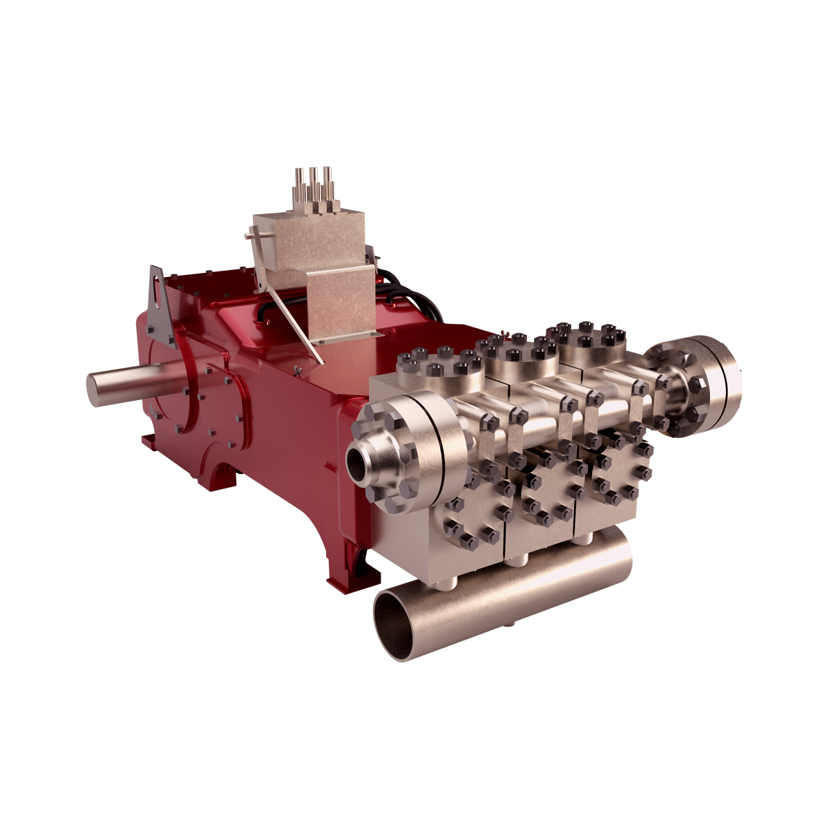
Positive displacements pumps are generally used on drilling rigs to pump high pressure and high volume of drilling fluids throughout a drilling system. There are several reasons why the positive displacement mud pumps are used on the rigs.
The duplex pumps (Figure 1) have two cylinders with double acting. It means that pistons move back and take in drilling mud through open intake valve and other sides of the same pistons, the pistons push mud out through the discharge valves.
When the piston rod is moved forward, one of intake valves is lift to allow fluid to come in and one of the discharge valve is pushed up therefore the drilling mud is pumped out of the pump (Figure 2).
On the other hand, when the piston rod is moved backward drilling fluid is still pumped. The other intake and discharge valve will be opened (Figure 3).
The triplex pumps have three cylinders with single acting. The pistons are moved back and pull in drilling mud through open intake valves. When the pistons are moved forward and the drilling fluid is pushed out through open discharge valves.
On the contrary when the piston rods are moved backward, the intake valve are opened allowing drilling fluid coming into the pump (Figure 6). This video below shows how a triplex mud pump works.
Because each pump has power rating limit as 1600 hp, this will limit capability of pump. It means that you cannot pump at high rate and high pressure over what the pump can do. Use of a small liner will increase discharge pressure however the flow rate is reduces. Conversely, if a bigger liner is used to deliver more flow rate, maximum pump pressure will decrease.
As you can see, you can have 7500 psi with 4.5” liner but the maximum flow rate is only 297 GPM. If the biggest size of liner (7.25”) is used, the pump pressure is only 3200 psi.
Finally, we hope that this article would give you more understanding about the general idea of drilling mud pumps. Please feel free to add more comments.

Oil and Gas drilling process - Pupm output for Triplex and Duplex pumpsTriplex Pump Formula 1 PO, bbl/stk = 0.000243 x ( in) E.xample: Determine the pump output, bbl/stk, at 100% efficiency for a 7" by 12". triplex pump: PO @ 100%,= 0.000243 x 7 x12 PO @ 100% = 0.142884bbl/stk Adjust the pump output for 95% efficiency: Decimal equivalent = 95 + 100 = 0.95 PO @ 95% = 0.142884bbl/stk x 0.95 PO @ 95% = 0.13574bbl/stk Formula 2 PO, gpm = [3(D x 0.7854)S]0.00411 x SPM where D = liner diameter, in. S = stroke length, in. SPM = strokes per minute Determine the pump output, gpm, for a 7" by 12". triplex pump at 80 strokes per minute: PO, gpm = [3(7 x 0.7854) 1210.00411 x 80 PO, gpm = 1385.4456 x 0.00411 x 80 PO = 455.5 gpm
Example:Duplex Pump Formula 1 0.000324 x (liner diameter, in) x ( stroke lengh, in) = ________ bbl/stk -0.000162 x (rod diameter, in) x ( stroke lengh, in) = ________ bbl/stk Pump out put @ 100% eff = ________bbl/stk Example: Determine the output, bbl/stk, of a 5 1/2" by 14" duplex pump at 100% efficiency. Rod diameter = 2.0": 0.000324 x 5.5 x 14 = 0.137214bbl/stk -0.000162 x 2.0 x 14 = 0.009072bbl/stk Pump output @ 100% eff. = 0.128142bbl/stk Adjust pump output for 85% efficiency: Decimal equivalent = 85 100 = 0.85 PO@85%)= 0.128142bbl/stk x 0.85 PO@ 85% = 0.10892bbl/stk Formula 2
PO. bbl/stk = 0.000162 x S[2(D) - d] where S = stroke length, in. D = liner diameter, in. d = rod diameter, in. Example: Determine the output, bbl/stk, of a 5 1/2". by 14". duplex pump @ 100% efficiency. Rod diameter = 2.0in.: PO@100%=0.000162 x 14 x [ 2 (5.5) - 2 ] PO @ 100%)= 0.000162 x 14 x 56.5 PO@ 100%)= 0.128142bbl/stk Adjust pump output for 85% efficiency: PO@85%,= 0.128142bb/stkx 0.85 PO@8.5%= 0.10892bbl/stk Metric calculation Pump output, liter/min = pump output. liter/stk x pump speed, spm. S.I. units calculation Pump output, m/min = pump output, liter/stk x pump speed, spm. Mud Pumps Mud pumps drive the mud around the drilling system. Depending on liner size availability they can be set up to provide high pressure and low flow rate, or low pressure and high flow rate. Analysis of the application and running the Drill Bits hydraulics program will indicate which liners to recommend. Finding the specification of the mud pumps allows flow rate to be calculated from pump stroke rate, SPM. Information requiredo Pump manufacturer o Number of pumps o Liner size and gallons per revolution Weight As a drill bit cutting structure wears more weight will be required to achieve the same RoP in a homogenous formation. PDC wear flats, worn inserts and worn milled tooth teeth will make the bit drill less efficiently. Increase weight in increments of 2,000lbs approx. In general, weight should be applied before excessive rotary speed so that the cutting structure maintains a significant depth of cut to stabilise the bit and prevent whirl. If downhole weight measurements are available they can be used in combination with surface measurements to gain a more accurate representation of what is happening in the well bore.
Many groundwater professionals prefer using charts and tables to determine these values, and those tabulated references are available in the appendices of many textbooks and in handbooks from cement or drilling fluid suppliers.
This approach works well but relying on a printed reference is not without the risk since the wrong value can still be selected from the fine print of a reference table, or the reference document can be damaged or lost (e.g., dropped in the mud pit) altogether.
So, let’s address the alternative approach of using simple mathematical formulas to determine the same information. Although the reliance on a single sheet of paper to obtain the needed value is avoided with this approach, the potential for human error or miscalculation remains, meaning regardless of the approach, great care in determining such values is prudent.
As we consider the various calculations that enable us to determine the values of length, weight, pressure, volume, flow velocity, etc., we should remain mindful of the units of measure we’re dealing with. The groundwater industry uses units of measure that are somewhat intermingled with other units from associated disciplines such as engineering, surface water hydrology, and the oil and gas drilling industry.
The intermediate casing can be sealed using the pressure grouting technique (Figure 3) to pump cement slurry down through the drill pipe and out to the annulus through a float shoe (a drillable check valve connected to the base of the casing). The inside of the intermediate casing is kept full of water during the cement placement to equilibrate hydraulic pressures inside and outside the casing. After the intermediate casing is sealed with the pressure grouted cement, the float shoe can be drilled out and the borehole advanced for installation of the screen and filter pack in the lower part of the well.
For heavier-walled casing materials or deeper wells, there are situations where the “string weight” of the casing and screen may exceed the safe hang weight of the casing string, or even exceed the mast capacity of the drilling rig. A good rule-of-thumb is to maintain a rig mast capacity that is no less than 1.5 times the string weight.
There are several calculations that are commonly applied by drilling fluid engineers (mud engineers) to determine the time period required for the fluid to move from one location in the borehole to another. Some of the more common equations are described below.
The uphole velocity calculation provides a determination of the speed at which the drilling mud will flow as it moves up the borehole. For direct air rotary or reverse circulation drilling methods, the uphole velocity is high, so this calculation is generally applicable only for the direct mud-rotary drilling method. The formula for uphole velocity is:
Notice the uphole velocity formula is similar to the annular volume formula in that both those calculations use the factor (D2 – d2) to address the cross-sectional area of the annulus. However, the constants in these two formulas are different (0.005454 versus 24.51), which can be confusing. Keep in mind, however, that the constants primarily just provide unit conversions.
Thebottoms-up time calculation enables us to determine the time period for the drilling fluid (and the cuttings it is carrying) to travel from the drill bit up to the land surface. This is illustrated in Figure 6(A).
We can calculate the bottoms-up time by using the uphole velocity formula with the borehole depth and drilling mud flow rate plugged in, but that flow rate is being generated by the mud pump, and positive displacement mud pumps (duplex or triplex) are almost never equipped with a flow meter. To determine the flow coming from the mud pump, we can use the formulas:
Remember the strokes are counted in both the forward and backward directions on a duplex pump, but only in the forward direction on a triplex pump. Drillers often have reference charts that provide oilfield barrels per stroke (bbl/stroke), which can be converted to gpm by timing the strokes per minute and converting barrels to gallons (1 barrel = 42 gallons).
The round-trip time enables us to see the result of drilling fluid additives, as indicated by the return flow of fluids at the land surface, as is illustrated in Figure 6(B). The round-trip time calculation is the same as bottoms-up time, but with the travel time of fluid to displace the drill pipe added in.
A specified volume of drilling fluids (called a pill) can be circulated to a particular depth interval within the borehole (called spotting), so that the additives in the pill of drilling mud can address the borehole problem at a particular depth of the borehole. This is shown in Figure 6(C).
The calculation for time required to spot a pill of drillingfluid involves determining the pumping time (at the calculated flow rate) required to displace the fluid so that the drilling mud additives are located adjacent to the problematic interval. This approach is used by mud engineers to address problems such as lost circulation or stuck drill pipe.
The formulas and calculations provided in this column and elsewhere provide important tools for us to quantify the variables we need for water well design and construction. However, it is important to remember that “doing the math” is not a replacement for applying professional knowledge and consideration to determine whether the mathematical result makes common sense.

The driller’s method requires two circulations to kill the well. The first circulation is to circulate influx out of the well with original mud weight. The second circulation is to kill the well with kill weight fluid. During the first circulation, the bottom hole pressure remains constant due to maintain drill pipe pressure constant while circulating. For the second circulation, in order to maintain constant bottom hole pressure, casing pressure is held constant while circulating kill mud to the bit. Once the kill mud passes the bit, the drill pipe pressure will be held constant until the kill weight mud is on surface and there is no sign of influx in the annulus.
The Wait and Weight method requires only one circulation. The influx will be circulated out while the kill weight mud is displaced into the well simultaneously. While pumping the kill fluid from surface to the bit, drill pipe pressure schedule must be strictly followed. After that the drill pipe pressure is maintained constant until the kill mud returns back to surface. Some people call the Wait and Weight method as “Engineer’s Method” because there are more calculations compared to the Driller’s method.
For W&W method, kill weight mud must be prepared prior to circulation therefore the drill string is in static condition with no circulation for a while. There is high chance for wellbore to collapse and pack the drillstring.
Shoe will be exerted the maximum pressure when top of gas kick is at the casing shoe. Once the gas pass the shoe, the shoe pressure will remain constant. The W&W can reduce shoe pressure when the kill weight mud goes into the annulus before the top of gas arrives at shoe. If you have larger drillstring volume than annular volume, you will not be able to lower the shoe pressure using Wait and Weight method. However, if time to prepare the kill weight mud is very long, gas migration will increase shoe pressure. There will be a possibility that using W&W can create more shoe pressure due to gas migration while preparation of drilling mud.
Nowadays, oil-based drilling fluid is widely used for drilling operation. Gas will be soluble in oil based mud and it will not be able to detect at the bottom. Gas may expand when it moves almost to the surface and it is often above the shoe. Hence, W&W will not help reduce shoe pressure.
Around the world, there are a lot of drilling rigs which don’t have great capability to mix drilling fluid effectively, therefore, kill weight mud cannot not be mixed as quickly as the operation required for killing the well using W&W. The Driller’s Method will not have this issue because the circulation can be performed right away. Waiting for preparing kill weight mud for a long time can lead to increasing in shoe and surface pressure due to migration of gas.
If the bit nozzles are plugged during the first circulation of Driller’s method, drill pipe pressure is allowed to increase temporary by maintaining casing pressure constant until the drill pipe pressure stabilizes and then the new circulating pressure. During the second circulation of Driller’s method, if the plugged nozzles are encountered, casing pressure must maintain until the kill mud to the bit and then change to hold drill pipe pressure shown on the gauge.
Well ballooning effect is a natural phenomenon occurring when formations take drilling mud when the pumps are on and the formations give the mud back when the pumps are off. When ballooning is observed, it must be treated as kick. If W&W is utilized to manage this issue at the beginning, the additional mud weight can increase complexity of wellbore ballooning situation. More mud weight can induce more mud losses and the situation will be worse. Since the Driller’s method does not require additional mud weight hence there is no increasing in wellbore pressure. Therefore, the ballooning situation will not become worse.
Deepwater condition is high-pressure and low-temperature conditions which are ideal case for hydrate. Therefore, there is a high chance of hydrate formation in choke/kill lines and BOP when gas influx is taken in a deepwater well. Driller’s method will minimize hydrate issue because the circulation is established as soon as possible. The mud is still warm and the hydrate issue can possibly be mitigated. Conversely, killing the well using wait and weight method requires longer time to shut in because the kill mud must be properly prepared prior to circulating. The static condition will make the mud cool and it is a favorable condition for hydrate formation due to decreasing in temperature of drilling fluid.

Continental Emsco Drilling Products, Inc., which consisted of Emsco drilling machinery and Wilson mobile rigs, was purchased by National-Oilwell, Inc on July 7, 1999. To our knowledge, no pumps have been manufactured and sold under the Emsco brand name since National-Oilwell acquired them.
Fairbanks Morse pumps are currently manufactured in Kansas City, Kansas. Fairbanks Morse is a division of Pentair ever since August, 1997 when Pentair purchased the General Signal Pump Group.
Gaso pumps are manufactured by National Oilwell Varco. Gaso was acquired as "Wheatley Gaso" by National-Oilwell in the year 2000. At the time, Wheatley Gaso was owned by Halliburton.
Skytop Brewster pumps are no longer available as new pumps. Skytop Brewster(Cnsld Gold), a unit of Hansen PLC"s Consolidated Gold Fields subsidiary, was acquired while in bankruptcy by National-Oilwell, Inc. in November, 1999.
Mud pump liner selection in today"s drilling operations seldom (at best) considers electrical implications. Perhaps, with more available useful information about the relationships between mud pump liner size and operational effects on the electrical system, certain potential problems can be avoided. The intent of this paper is to develop those relationships and show how they affect an electrical system on example SCR rigs.Introduction
There, seems to be little consideration for the relationships between liner size and demand on a rig"s engine/generator set(s). Yet, consideration for this relationship can prove to be very helpful to drillers and operators in efficiency of a rig"s electrical system. In order to develop the relationships and help drillers and operators understand the importance of each, relationships between liner size, pump speed, pump pressure, and electrical power will be developed. Only basic physical laws will be used to develop the relationships; and, once developed, the relationships are readily applied to realistic examples utilizing a mud pump manufacturer"s pump data. Finally, conclusions will be drawn from the examples.DEVELOPMENT OF RELATIONSHIPS BASIC RELATIONSHIPS
where HHP= Hydraulic horsepower, GPM = Mud pump volumetric flow rate in gallons per minute, and PST Mud pump output pressure in pounds peer square inch.
Hydraulic horsepower is reflected to the mud pump motor via a multiplier for mechanical efficiency. it follows that motor horsepower is then represented by


 8613371530291