
drilling formulas mud pump output in stock

Rig pump output, normally in volume per stroke, of mud pumps on the rig is one of important figures that we really need to know because we will use pump out put figures to calculate many parameters such as bottom up strokes, wash out depth, tracking drilling fluid, etc. In this post, you will learn how to calculate pump out put for triplex pump and duplex pump in bothOilfield and Metric Unit.
Bourgoyne, A.J.T., Chenevert , M.E. & Millheim, K.K., 1986. SPE Textbook Series, Volume 2: Applied Drilling Engineering, Society of Petroleum Engineers.

Positive displacements pumps are generally used on drilling rigs to pump high pressure and high volume of drilling fluids throughout a drilling system. There are several reasons why the positive displacement mud pumps are used on the rigs.
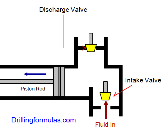
The duplex pumps (Figure 1) have two cylinders with double acting. It means that pistons move back and take in drilling mud through open intake valve and other sides of the same pistons, the pistons push mud out through the discharge valves.
When the piston rod is moved forward, one of intake valves is lift to allow fluid to come in and one of the discharge valve is pushed up therefore the drilling mud is pumped out of the pump (Figure 2).
On the other hand, when the piston rod is moved backward drilling fluid is still pumped. The other intake and discharge valve will be opened (Figure 3).
The triplex pumps have three cylinders with single acting. The pistons are moved back and pull in drilling mud through open intake valves. When the pistons are moved forward and the drilling fluid is pushed out through open discharge valves.
On the contrary when the piston rods are moved backward, the intake valve are opened allowing drilling fluid coming into the pump (Figure 6). This video below shows how a triplex mud pump works.
Because each pump has power rating limit as 1600 hp, this will limit capability of pump. It means that you cannot pump at high rate and high pressure over what the pump can do. Use of a small liner will increase discharge pressure however the flow rate is reduces. Conversely, if a bigger liner is used to deliver more flow rate, maximum pump pressure will decrease.
As you can see, you can have 7500 psi with 4.5” liner but the maximum flow rate is only 297 GPM. If the biggest size of liner (7.25”) is used, the pump pressure is only 3200 psi.
Finally, we hope that this article would give you more understanding about the general idea of drilling mud pumps. Please feel free to add more comments.
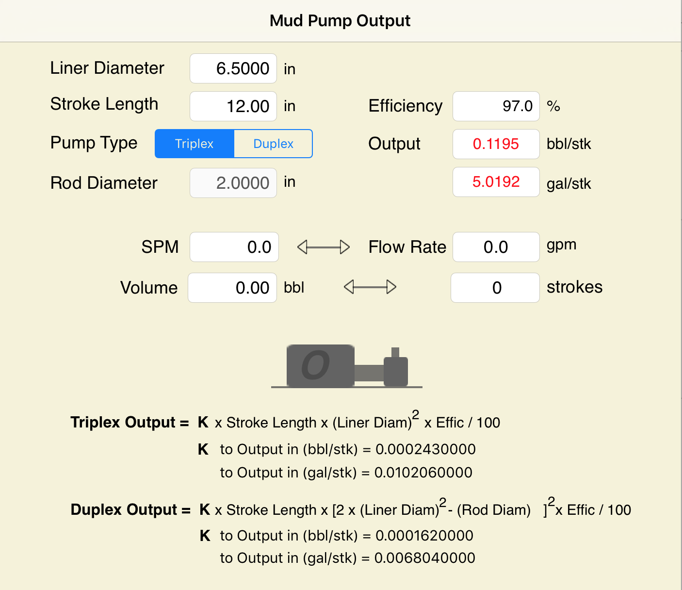
Pump Output per Stroke (PO): The calculator returns the pump output per stroke in barrels (bbl). However this can be automatically converted to other volume units (e.g. gallons or liters) via the pull-down menu.
A triplex mud (or slush) pump has three horizontal plungers (cylinders) driven off of one crankshaft. Triplex mud pumps are often used for oil drilling.

Oil and Gas drilling process - Pupm output for Triplex and Duplex pumpsTriplex Pump Formula 1 PO, bbl/stk = 0.000243 x ( in) E.xample: Determine the pump output, bbl/stk, at 100% efficiency for a 7" by 12". triplex pump: PO @ 100%,= 0.000243 x 7 x12 PO @ 100% = 0.142884bbl/stk Adjust the pump output for 95% efficiency: Decimal equivalent = 95 + 100 = 0.95 PO @ 95% = 0.142884bbl/stk x 0.95 PO @ 95% = 0.13574bbl/stk Formula 2 PO, gpm = [3(D x 0.7854)S]0.00411 x SPM where D = liner diameter, in. S = stroke length, in. SPM = strokes per minute Determine the pump output, gpm, for a 7" by 12". triplex pump at 80 strokes per minute: PO, gpm = [3(7 x 0.7854) 1210.00411 x 80 PO, gpm = 1385.4456 x 0.00411 x 80 PO = 455.5 gpm
Example:Duplex Pump Formula 1 0.000324 x (liner diameter, in) x ( stroke lengh, in) = ________ bbl/stk -0.000162 x (rod diameter, in) x ( stroke lengh, in) = ________ bbl/stk Pump out put @ 100% eff = ________bbl/stk Example: Determine the output, bbl/stk, of a 5 1/2" by 14" duplex pump at 100% efficiency. Rod diameter = 2.0": 0.000324 x 5.5 x 14 = 0.137214bbl/stk -0.000162 x 2.0 x 14 = 0.009072bbl/stk Pump output @ 100% eff. = 0.128142bbl/stk Adjust pump output for 85% efficiency: Decimal equivalent = 85 100 = 0.85 PO@85%)= 0.128142bbl/stk x 0.85 PO@ 85% = 0.10892bbl/stk Formula 2
PO. bbl/stk = 0.000162 x S[2(D) - d] where S = stroke length, in. D = liner diameter, in. d = rod diameter, in. Example: Determine the output, bbl/stk, of a 5 1/2". by 14". duplex pump @ 100% efficiency. Rod diameter = 2.0in.: PO@100%=0.000162 x 14 x [ 2 (5.5) - 2 ] PO @ 100%)= 0.000162 x 14 x 56.5 PO@ 100%)= 0.128142bbl/stk Adjust pump output for 85% efficiency: PO@85%,= 0.128142bb/stkx 0.85 PO@8.5%= 0.10892bbl/stk Metric calculation Pump output, liter/min = pump output. liter/stk x pump speed, spm. S.I. units calculation Pump output, m/min = pump output, liter/stk x pump speed, spm. Mud Pumps Mud pumps drive the mud around the drilling system. Depending on liner size availability they can be set up to provide high pressure and low flow rate, or low pressure and high flow rate. Analysis of the application and running the Drill Bits hydraulics program will indicate which liners to recommend. Finding the specification of the mud pumps allows flow rate to be calculated from pump stroke rate, SPM. Information requiredo Pump manufacturer o Number of pumps o Liner size and gallons per revolution Weight As a drill bit cutting structure wears more weight will be required to achieve the same RoP in a homogenous formation. PDC wear flats, worn inserts and worn milled tooth teeth will make the bit drill less efficiently. Increase weight in increments of 2,000lbs approx. In general, weight should be applied before excessive rotary speed so that the cutting structure maintains a significant depth of cut to stabilise the bit and prevent whirl. If downhole weight measurements are available they can be used in combination with surface measurements to gain a more accurate representation of what is happening in the well bore.

This worksheet takes inputs for the rig pumps and (optionally) hole and pipe sizes. It outputs pump flow rates and power, also fluid velocity if diameters entered.

Many groundwater professionals prefer using charts and tables to determine these values, and those tabulated references are available in the appendices of many textbooks and in handbooks from cement or drilling fluid suppliers.
This approach works well but relying on a printed reference is not without the risk since the wrong value can still be selected from the fine print of a reference table, or the reference document can be damaged or lost (e.g., dropped in the mud pit) altogether.
So, let’s address the alternative approach of using simple mathematical formulas to determine the same information. Although the reliance on a single sheet of paper to obtain the needed value is avoided with this approach, the potential for human error or miscalculation remains, meaning regardless of the approach, great care in determining such values is prudent.
As we consider the various calculations that enable us to determine the values of length, weight, pressure, volume, flow velocity, etc., we should remain mindful of the units of measure we’re dealing with. The groundwater industry uses units of measure that are somewhat intermingled with other units from associated disciplines such as engineering, surface water hydrology, and the oil and gas drilling industry.
The intermediate casing can be sealed using the pressure grouting technique (Figure 3) to pump cement slurry down through the drill pipe and out to the annulus through a float shoe (a drillable check valve connected to the base of the casing). The inside of the intermediate casing is kept full of water during the cement placement to equilibrate hydraulic pressures inside and outside the casing. After the intermediate casing is sealed with the pressure grouted cement, the float shoe can be drilled out and the borehole advanced for installation of the screen and filter pack in the lower part of the well.
For heavier-walled casing materials or deeper wells, there are situations where the “string weight” of the casing and screen may exceed the safe hang weight of the casing string, or even exceed the mast capacity of the drilling rig. A good rule-of-thumb is to maintain a rig mast capacity that is no less than 1.5 times the string weight.
There are several calculations that are commonly applied by drilling fluid engineers (mud engineers) to determine the time period required for the fluid to move from one location in the borehole to another. Some of the more common equations are described below.
The uphole velocity calculation provides a determination of the speed at which the drilling mud will flow as it moves up the borehole. For direct air rotary or reverse circulation drilling methods, the uphole velocity is high, so this calculation is generally applicable only for the direct mud-rotary drilling method. The formula for uphole velocity is:
Notice the uphole velocity formula is similar to the annular volume formula in that both those calculations use the factor (D2 – d2) to address the cross-sectional area of the annulus. However, the constants in these two formulas are different (0.005454 versus 24.51), which can be confusing. Keep in mind, however, that the constants primarily just provide unit conversions.
Thebottoms-up time calculation enables us to determine the time period for the drilling fluid (and the cuttings it is carrying) to travel from the drill bit up to the land surface. This is illustrated in Figure 6(A).
We can calculate the bottoms-up time by using the uphole velocity formula with the borehole depth and drilling mud flow rate plugged in, but that flow rate is being generated by the mud pump, and positive displacement mud pumps (duplex or triplex) are almost never equipped with a flow meter. To determine the flow coming from the mud pump, we can use the formulas:
Remember the strokes are counted in both the forward and backward directions on a duplex pump, but only in the forward direction on a triplex pump. Drillers often have reference charts that provide oilfield barrels per stroke (bbl/stroke), which can be converted to gpm by timing the strokes per minute and converting barrels to gallons (1 barrel = 42 gallons).
The round-trip time enables us to see the result of drilling fluid additives, as indicated by the return flow of fluids at the land surface, as is illustrated in Figure 6(B). The round-trip time calculation is the same as bottoms-up time, but with the travel time of fluid to displace the drill pipe added in.
A specified volume of drilling fluids (called a pill) can be circulated to a particular depth interval within the borehole (called spotting), so that the additives in the pill of drilling mud can address the borehole problem at a particular depth of the borehole. This is shown in Figure 6(C).
The calculation for time required to spot a pill of drillingfluid involves determining the pumping time (at the calculated flow rate) required to displace the fluid so that the drilling mud additives are located adjacent to the problematic interval. This approach is used by mud engineers to address problems such as lost circulation or stuck drill pipe.
The formulas and calculations provided in this column and elsewhere provide important tools for us to quantify the variables we need for water well design and construction. However, it is important to remember that “doing the math” is not a replacement for applying professional knowledge and consideration to determine whether the mathematical result makes common sense.

Mr. Carter has over fifty five years" experience in domestic and international engineering and management positions in the area of drilling, completion and E&P waste management with Conoco, Baroid, and several other drilling contractors. He has conducted seminars and schools on fluids, rig equipment, and drilling engineering related subjects associated with drilling optimization, cost reduction, and well control. Tom has served as Chairman of the API standardization committee (SC 13) on Drilling and Completion Fluid Materials. He was a SPE Distinguished Lecturer in 1993 and served as the Editor of the SPE reprint series book on drilling fluids. Currently, he is a member of the Chevron Clear Leader Center serving as a Technical Learning Advisor in Houston. He coordinates and has teaching participation in several subject areas such as Coiled Tubing Operations, Directional Drilling, Drilling Fluids, Drilling Practices, Fundamentals for Drilling and Completion, HPHT Drilling and Completions, and Solids Control and Waste Management. He is still active in several industry organizations and was President of the Houston chapter of the American Association of Drilling Engineers, Coordinator for the SPE North American Forum Series, Membership Chairman of the editorial committee for the Journal of Petroleum Technology and on the Board of Directors for the Ocean Energy Center Society (Ocean Star rig museum in Galveston). He has published 20 technical publications and holds five U.S. patents. He graduated with a BS in Geology from Centenary College in Shreveport, Louisiana in 1963.

The driller’s method requires two circulations to kill the well. The first circulation is to circulate influx out of the well with original mud weight. The second circulation is to kill the well with kill weight fluid. During the first circulation, the bottom hole pressure remains constant due to maintain drill pipe pressure constant while circulating. For the second circulation, in order to maintain constant bottom hole pressure, casing pressure is held constant while circulating kill mud to the bit. Once the kill mud passes the bit, the drill pipe pressure will be held constant until the kill weight mud is on surface and there is no sign of influx in the annulus.
The Wait and Weight method requires only one circulation. The influx will be circulated out while the kill weight mud is displaced into the well simultaneously. While pumping the kill fluid from surface to the bit, drill pipe pressure schedule must be strictly followed. After that the drill pipe pressure is maintained constant until the kill mud returns back to surface. Some people call the Wait and Weight method as “Engineer’s Method” because there are more calculations compared to the Driller’s method.
For W&W method, kill weight mud must be prepared prior to circulation therefore the drill string is in static condition with no circulation for a while. There is high chance for wellbore to collapse and pack the drillstring.
Shoe will be exerted the maximum pressure when top of gas kick is at the casing shoe. Once the gas pass the shoe, the shoe pressure will remain constant. The W&W can reduce shoe pressure when the kill weight mud goes into the annulus before the top of gas arrives at shoe. If you have larger drillstring volume than annular volume, you will not be able to lower the shoe pressure using Wait and Weight method. However, if time to prepare the kill weight mud is very long, gas migration will increase shoe pressure. There will be a possibility that using W&W can create more shoe pressure due to gas migration while preparation of drilling mud.
Nowadays, oil-based drilling fluid is widely used for drilling operation. Gas will be soluble in oil based mud and it will not be able to detect at the bottom. Gas may expand when it moves almost to the surface and it is often above the shoe. Hence, W&W will not help reduce shoe pressure.
Around the world, there are a lot of drilling rigs which don’t have great capability to mix drilling fluid effectively, therefore, kill weight mud cannot not be mixed as quickly as the operation required for killing the well using W&W. The Driller’s Method will not have this issue because the circulation can be performed right away. Waiting for preparing kill weight mud for a long time can lead to increasing in shoe and surface pressure due to migration of gas.
If the bit nozzles are plugged during the first circulation of Driller’s method, drill pipe pressure is allowed to increase temporary by maintaining casing pressure constant until the drill pipe pressure stabilizes and then the new circulating pressure. During the second circulation of Driller’s method, if the plugged nozzles are encountered, casing pressure must maintain until the kill mud to the bit and then change to hold drill pipe pressure shown on the gauge.
Well ballooning effect is a natural phenomenon occurring when formations take drilling mud when the pumps are on and the formations give the mud back when the pumps are off. When ballooning is observed, it must be treated as kick. If W&W is utilized to manage this issue at the beginning, the additional mud weight can increase complexity of wellbore ballooning situation. More mud weight can induce more mud losses and the situation will be worse. Since the Driller’s method does not require additional mud weight hence there is no increasing in wellbore pressure. Therefore, the ballooning situation will not become worse.
Deepwater condition is high-pressure and low-temperature conditions which are ideal case for hydrate. Therefore, there is a high chance of hydrate formation in choke/kill lines and BOP when gas influx is taken in a deepwater well. Driller’s method will minimize hydrate issue because the circulation is established as soon as possible. The mud is still warm and the hydrate issue can possibly be mitigated. Conversely, killing the well using wait and weight method requires longer time to shut in because the kill mud must be properly prepared prior to circulating. The static condition will make the mud cool and it is a favorable condition for hydrate formation due to decreasing in temperature of drilling fluid.

A triplex pump is a classification of mud pump commonly used for oil drilling. The primary purpose of a mud pump is to circulate the mud, also called drilling fluid, during drilling operations. It works by forcing drilling fluid down the hollow drill string and back up through the annulus.
Duplex pumps have two pistons or plungers while triplex pumps contain three. This means duplex pumps must move faster to generate the same pressure levels as triplex pumps, consequently wearing their parts faster, and often causing a pulsating effect.
The pump should be able to provide adequate horsepower while drilling all hole sections. The extreme hole conditions occur when the surface hole and the total hole depth are drilled. Drilling the surface hole requires the highest mud flow, and drilling at the total depth requires the highest pump pressure.
Plastic viscosity and yield point are the two parameters used to describe the rheological characteristics of Bingham plastic fluids. The minimum required mud flow rate from the mud pump is equal to the minimum required mud velocity times the maximum possible cross-sectional area of annular space during drilling.
The macerator pump uses a stainless steel fast-rotating cutting blade to convert solids and fluids into a fine slurry that is discharged under pressure through small-diameter piping (¾-inch or 1-inch) and expelled into the sewage line or septic tank.
Example on how to calculate mud pump output for triplex pump. Method III Hydraulic Slide Rule and Pump Performance Charts. Mud Pump Output Calculators. What is The Triplex Mud Pump? A positive-displacement reciprocating pump which is equipped with three plungers.
A positive-displacement reciprocating pump which is equipped with three plungers. Triplex pumps are the most known configuration of pump used in any drilling and workover operations.
Triplex pumps are the most known configuration of pump used in any drilling and workover operations. Triplex mud pumps used in drilling or workover operations generally are able to handle a wide range of mud and completion fluids types, including corrosive fluids, abrasive fluids and slurries which includes relatively large particulates.
National Oilwell Varco’s 12-P-160 Mud Pump is rated at 1600 input horsepower (1193 kw) at 120 strokes per minute, with a 12-inch (304.8 mm) stroke. Multiple liner sizes allow pressures and volumes to handle circulation requirements in deep drilling applications. Model 12-P-160 triPlex Mud PuMP Performance
Electronic Pump Stroke Counters are a vital part to any drilling rig operation. When a mud pump is in operation, the driller must know how much mud is flowing down hole in order to keep the operation running at peak efficiency. Pump stroke counters assist the driller by measuring the mud pump’s strokes per minute and total strokes. So, how does a pump stroke counter tally the mud pump’s strokes
Electronic Pump Stroke Counters are a vital part to any drilling rig operation. When a mud pump is in operation, the driller must know how much mud is flowing down hole in order to keep the operation running at peak efficiency. Pump stroke counters assist the driller by measuring the mud pump’s strokes per minute and total strokes. So, how does a pump stroke counter tally the mud pump’s strokes, and why it is important? In order to understand that, you’ll need to know some basic information about mud pumps.
Knowing how a mud pump functions is important in understanding the role a pump stroke counter plays in rig operations. Mud pumps act as the heart of the drilling rig, similar to how our heart works. Just as our heart circulates blood throughout our bodies, a mud pump circulates essential drilling mud down the hole and back up to the surface. Mud tanks house drilling mud, and a mud pump draws the fluid from the mud pump. A piston draws mud in on the backstroke through the open intake valve and pushes mud through the discharge valve and sends it towards the rig. By circulating fluid, the mud pump ensures that the drill bit is cool and lubricated and that cuttings are flushed from the hole. The two main kinds of pumps used are duplex and triplex pumps, where the duplex pump has two pistons and the triplex pump has three. Whether the rig is using a duplex or triplex pump, it is important to know how many strokes per second the pistons are moving. The driller monitors strokes per minute to determine how much costly, yet essential, mud is being pumped into the system with the use of a mud pump stroke counter system. Now, that you know about mud pumps, you’ll need to know what’s in a stroke counter system.
Stroke Counter — The stroke counter stainless steel box is mounted on the driller’s console and is either square or rectangular in shape, depending on the number of pumps it is monitoring. Stroke counters will show strokes per minute and total strokes, and when a particular mud pump is operating the strokes/minute and total strokes will be displayed. Power is supplied by a 3.6 volt lithium battery, and the counter contains a crystal-controlled real time clock with 100 parts per million accuracy or better. Each counter is mounted to the console with 1/4” stainless steel hex head bolts, lock washers and nuts.
Micro Limit Switch — The micro switch is connected to a c clamp near the mud pump piston. The micro switch stainless steel rod (sometimes called a whisker) sticks out in the piston housing near the piston. As the piston passes the rod, it moves the rod and the switch sends an electronic signal back to the counter. The counter increases by one each time the piston moves the rod, counting the mud pump’s strokes. The switch’s signal is then transmitted to the stroke counter. These micro switches are built to stand up to demanding outdoor conditions. They can withstand shock, equipment vibration, extreme temperatures, water and dust.
Cable and Junction Box – A cable is connected to the back of the pump stroke counter and then to the junction box. From the junction box, the cables travel to the limit switches.
Pump Stroke Counters are like a blood pressure machine. Each time our heart pumps, a blood pressure machine reads our systolic and diastolic blood pressure by way of our pulse. A mud pump stroke counter functions in much the same way. Just as a blood pressure machine detects our pulse so too does a limit switch rod detect the movement of the piston. When the stainless steel rod is moved, the micro limit switch detects the movement. The signal is sensed as a contact closure, and it is transmitted to the stroke counter where the contact closure is converted to a logic pulse. The pulse feeds two separate circuits. The total strokes circuit reads and displays the closures one at a time, totaling them up to reveal the total strokes in the LED window. The second pulse is sent along a separate circuit which is a rate circuit. This rate circuit will average the closures against the real time clock. The result is displayed as the total strokes per minute.
Pump stroke counters are essential to drilling rig operations because they measure the efficiency of mud pumps. Knowing strokes per minute and total strokes of the pistons helps the driller to determine if the correct amount of mud is going down hole. Having this information aids in running a drilling rig at peak efficiency, assists in extending drill bit life, and avoids costly overuse of drilling rig mud. Unsure which pump stroke counter is right for your application? Give our friendly, knowledgeable staff a call or email. We’ll keep you turning right.


 8613371530291