
drilling mud pump calculations supplier

Continental Emsco Drilling Products, Inc., which consisted of Emsco drilling machinery and Wilson mobile rigs, was purchased by National-Oilwell, Inc on July 7, 1999. To our knowledge, no pumps have been manufactured and sold under the Emsco brand name since National-Oilwell acquired them.
Fairbanks Morse pumps are currently manufactured in Kansas City, Kansas. Fairbanks Morse is a division of Pentair ever since August, 1997 when Pentair purchased the General Signal Pump Group.
Gaso pumps are manufactured by National Oilwell Varco. Gaso was acquired as "Wheatley Gaso" by National-Oilwell in the year 2000. At the time, Wheatley Gaso was owned by Halliburton.
Skytop Brewster pumps are no longer available as new pumps. Skytop Brewster(Cnsld Gold), a unit of Hansen PLC"s Consolidated Gold Fields subsidiary, was acquired while in bankruptcy by National-Oilwell, Inc. in November, 1999.

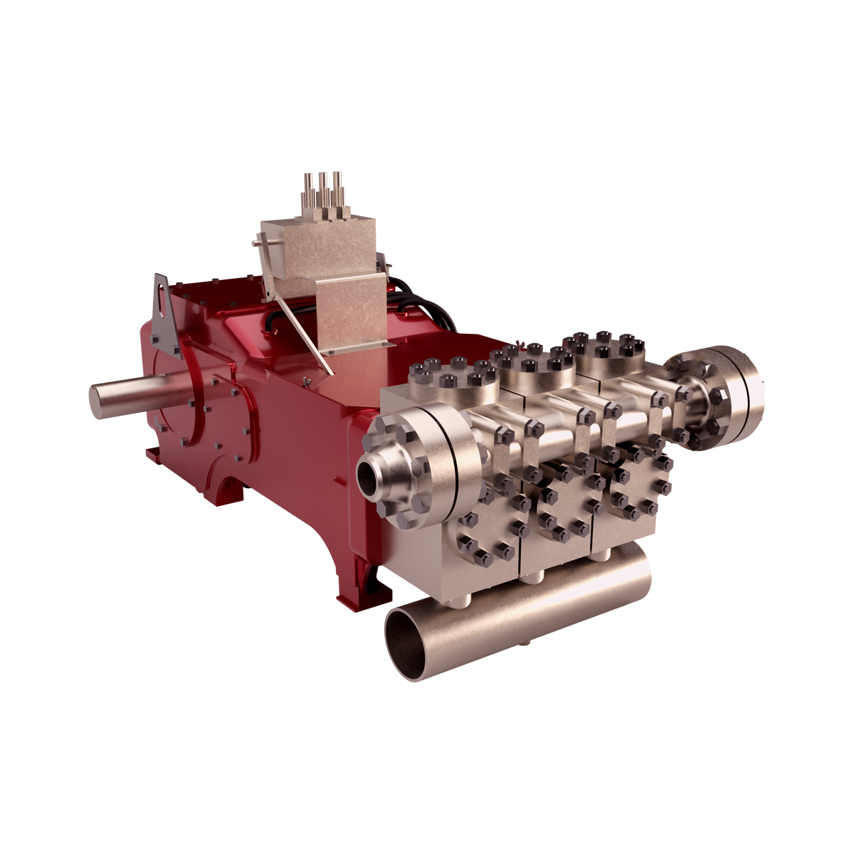
The 2,200-hp mud pump for offshore applications is a single-acting reciprocating triplex mud pump designed for high fluid flow rates, even at low operating speeds, and with a long stroke design. These features reduce the number of load reversals in critical components and increase the life of fluid end parts.
The pump’s critical components are strategically placed to make maintenance and inspection far easier and safer. The two-piece, quick-release piston rod lets you remove the piston without disturbing the liner, minimizing downtime when you’re replacing fluid parts.

Rig pump output, normally in volume per stroke, of mud pumps on the rig is one of important figures that we really need to know because we will use pump out put figures to calculate many parameters such as bottom up strokes, wash out depth, tracking drilling fluid, etc. In this post, you will learn how to calculate pump out put for triplex pump and duplex pump in bothOilfield and Metric Unit.
Bourgoyne, A.J.T., Chenevert , M.E. & Millheim, K.K., 1986. SPE Textbook Series, Volume 2: Applied Drilling Engineering, Society of Petroleum Engineers.
Having a quality mud pump is a critical part of keeping your oil well drilling system running as smoothly as possible. Dragon carries a wide range of mud pumps for systems of all kinds and jobs of all sizes. We also carry a 50 BPM mud mixing table to make drilling fluid mixing more efficient and accurate so you can always get the job done safely and correctly. View our full well service pump and mud pump selection to find the right system for your job site, or check out the rest of our drilling rigs for even more options.

During drilling in Oil and Gas exploration, drilling mud or Bentonite is pumped into boreholes for multiple reasons. Pumping drill mud into boreholes cools the drill bit as well as bringing drill cuttings to the surface as the way in which mud is pumped into boreholes forms a closed loop system. The use of drilling mud also provides hydrostatic pressure to prevent liquids such as oil and gas rising to the surface, as drilling mud is thixotropic meaning when it is not agitated it stiffens forming a mud which is an effective liquid and gas barrier.
The drilling industry has roots dating back to the Han Dynasty in China. Improvements in rig power and equipment design have allowed for many advances in the way crude oil and natural gas are extracted from the ground. Diesel/electric oil drilling rigs can now drill wells more than 4 miles in depth. Drilling fluid, also called drilling mud, is used to help transfer the dirt or drill cuttings from the action of the drilling bit back to the surface for disposal. Drill cuttings can vary in shape and size depending on the formation or design of the drill bit used in the process.
Watch the video below to see how the EDDY Pump outperforms traditional pumps when it comes to high solids and high viscosity materials commonly found on oil rigs.
Solids control equipment including shakers, hydro-cyclones, and centrifuges are utilized to clean the drill cuttings from the drilling fluid, which then allows it to be reused and recirculated. The circuit includes the mixing of the drilling fluid in the rig tanks.
The drilling fluid is prepared to control fluid loss to the formation by the addition of chemicals or mineral agents. Commercial barite or other weighting agents are added to control the hydrostatic pressure exuded on the bottom of the well which controls formation pressures preventing fluid or gas intrusion into the wellbore.
The fluid is charged into high-pressure mud pumps which pump the drilling mud down the drill string and out through the bit nozzles cleaning the hole and lubricating the drill bit so the bit can cut efficiently through the formation. The bit is cooled by the fluid and moves up the space between the pipe and the hole which is called the annulus. The fluid imparts a thin, tough layer on the inside of the hole to protect against fluid loss which can cause differential sticking.
The fluid rises through the blowout preventers and down the flowline to the shale shakers. Shale shakers are equipped with fine screens that separate drill cutting particles as fine as 50-74 microns. Table salt is around 100 microns, so these are fine cuttings that are deposited into the half-round or cuttings catch tank. The drilling fluid is further cleaned with the hydro-cyclones and centrifuges and is pumped back to the mixing area of the mud tanks where the process repeats.
The drill cuttings contain a layer of drilling fluid on the surface of the cuttings. As the size of the drill cuttings gets smaller the surface area expands exponentially which can cause rheological property problems with the fluid. The fluid will dehydrate and may become too thick or viscous to pump so solids control and dilution are important to the entire drilling process.
One of the most expensive and troubling issues with drilling operations is the handling, processing, and circulation of drilling mud along with disposing of the unwanted drill cuttings. The drilling cuttings deposited in the half round tank and are typically removed with an excavator that must move the contents of the waste bin or roll-off box. The excavators are usually rented for this duty and the equipment charges can range from $200-300/day. Add in the cost for the day and night manpower and the real cost for a single excavator can be as much as $1800/day.
Offshore drilling rigs follow a similar process in which the mud is loaded into empty drums and held on the oil platform. When a certain number of filled drums is met, the drums are then loaded onto barges or vessels which take the drilling mud to the shore to unload and dispose of.
Oil field drilling operations produce a tremendous volume of drill cuttings that need both removal and management. In most cases, the site managers also need to separate the cuttings from the drilling fluids so they can reuse the fluids. Storing the cuttings provides a free source of stable fill material for finished wells, while other companies choose to send them off to specialty landfills. Regardless of the final destination or use for the cuttings, drilling and dredging operations must have the right high solids slurry pumps to move them for transport, storage, or on-site processing. Exploring the differences in the various drilling fluids, cutting complications, and processing options will reveal why the EDDY Pump is the best fit for the job.
The Eddy Pump is designed to move slurry with solid content as high as 70-80 % depending on the material. This is an ideal application for pumping drill cuttings. Drill cuttings from the primary shakers are typically 50% solids and 50% liquids. The Eddy Pump moves these fluids efficiently and because of the large volute chamber and the design of the geometric rotor, there is very little wear on the pump, ensuring long life and greatly reduced maintenance cost for the lifetime of the pump.
plumbed to sweep the bottom of the collection tank and the pump is recessed into a sump allowing for a relatively clean tank when the solids are removed. The Eddy Pump is sized to load a roll-off box in 10-12 minutes. The benefit is cuttings handling is quicker, easier, safer, and allows for pre-planning loading where the labor of the solids control technician is not monopolized by loading cuttings. Here, in the below image, we’re loading 4 waste roll-off bins which will allow the safe removal of cuttings without fear of the half-round catch tank running over.
Mud cleaning systems such as mud shaker pumps and bentonite slurry pumps move the material over screens and through dryers and centrifuges to retrieve even the finest bits of stone and silt. However, the pump operators must still get the raw slurry to the drill cuttings treatment area with a power main pump. Slurry pumps designed around the power of an Eddy current offer the best performance for transferring cuttings throughout a treatment system.
Options vary depending on whether the company plans to handle drill cuttings treatment on-site or transport the materials to a remote landfill or processing facility. If the plan is to deposit the cuttings in a landfill or a long-term storage container, it’s best to invest in a pump capable of depositing the material directly into transport vehicles. Most dredging operations rely on multiple expensive vacuum trucks, secondary pumps, and extra pieces of equipment.
Using an EDDY Pump will allow a project to eliminate the need for excavators/operators to load drill cuttings, substantially lowering both labor and heavy equipment costs. The EDDY Pump also allows a company to eliminate vacuum trucks once used for cleaning the mud system for displacing fluids. Since the pump transfers muds of all types at constant pressure and velocity throughout a system of practically any size, there’s little need for extra equipment for manual transfer or clean up on the dredge site.
The EDDY Pump can fill up a truck in only 10 minutes (compared to an hour) by using a mechanical means such as an excavator. For this reason, most companies can afford one piece of equipment that can replace half a dozen other units.
This application for the Eddy Pump has the potential to revolutionize the drilling industry. Moving the excavator out of the “back yard” (the area behind the rig from the living quarters) will make cuttings handling a breeze. Trucking can be easier scheduled during daylight hours saving on overtime and incidences of fatigued driving. Rig-site forklifts can move the roll-off boxes out of the staging area and into the pump loading area. The operator can save money on excavators rental, damages, and keep the technician operating the solids control equipment.
The EDDY Pump is ideal for drilling mud pump applications and can be connected directly onto the drilling rigs to pump the drilling mud at distances over a mile for disposal. This eliminates the need for costly vacuum trucks and also the manpower needed to mechanically move the drilling mud. The reasons why the EDDY Pump is capable of moving the drilling mud is due to the hydrodynamic principle that the pump creates, which is similar to the EDDY current of a tornado. This tornado motion allows for the higher viscosity and specific gravity pumping ability. This along with the large tolerance between the volute and the rotor allows for large objects like rock cuttings to pass through the pump without obstruction. The large tolerance of the EDDY Pump also enables the pump to last many times longer than centrifugal pumps without the need for extended downtime or replacement parts. The EDDY Pump is the lowest total life cycle pump on the market.

When choosing a size and type of mud pump for your drilling project, there are several factors to consider. These would include not only cost and size of pump that best fits your drilling rig, but also the diameter, depth and hole conditions you are drilling through. I know that this sounds like a lot to consider, but if you are set up the right way before the job starts, you will thank me later.
Recommended practice is to maintain a minimum of 100 to 150 feet per minute of uphole velocity for drill cuttings. Larger diameter wells for irrigation, agriculture or municipalities may violate this rule, because it may not be economically feasible to pump this much mud for the job. Uphole velocity is determined by the flow rate of the mud system, diameter of the borehole and the diameter of the drill pipe. There are many tools, including handbooks, rule of thumb, slide rule calculators and now apps on your handheld device, to calculate velocity. It is always good to remember the time it takes to get the cuttings off the bottom of the well. If you are drilling at 200 feet, then a 100-foot-per-minute velocity means that it would take two minutes to get the cuttings out of the hole. This is always a good reminder of what you are drilling through and how long ago it was that you drilled it. Ground conditions and rock formations are ever changing as you go deeper. Wouldn’t it be nice if they all remained the same?
Centrifugal-style mud pumps are very popular in our industry due to their size and weight, as well as flow rate capacity for an affordable price. There are many models and brands out there, and most of them are very good value. How does a centrifugal mud pump work? The rotation of the impeller accelerates the fluid into the volute or diffuser chamber. The added energy from the acceleration increases the velocity and pressure of the fluid. These pumps are known to be very inefficient. This means that it takes more energy to increase the flow and pressure of the fluid when compared to a piston-style pump. However, you have a significant advantage in flow rates from a centrifugal pump versus a piston pump. If you are drilling deeper wells with heavier cuttings, you will be forced at some point to use a piston-style mud pump. They have much higher efficiencies in transferring the input energy into flow and pressure, therefore resulting in much higher pressure capabilities.
Piston-style mud pumps utilize a piston or plunger that travels back and forth in a chamber known as a cylinder. These pumps are also called “positive displacement” pumps because they literally push the fluid forward. This fluid builds up pressure and forces a spring-loaded valve to open and allow the fluid to escape into the discharge piping of the pump and then down the borehole. Since the expansion process is much smaller (almost insignificant) compared to a centrifugal pump, there is much lower energy loss. Plunger-style pumps can develop upwards of 15,000 psi for well treatments and hydraulic fracturing. Centrifugal pumps, in comparison, usually operate below 300 psi. If you are comparing most drilling pumps, centrifugal pumps operate from 60 to 125 psi and piston pumps operate around 150 to 300 psi. There are many exceptions and special applications for drilling, but these numbers should cover 80 percent of all equipment operating out there.
The restriction of putting a piston-style mud pump onto drilling rigs has always been the physical size and weight to provide adequate flow and pressure to your drilling fluid. Because of this, the industry needed a new solution to this age-old issue.
As the senior design engineer for Ingersoll-Rand’s Deephole Drilling Business Unit, I had the distinct pleasure of working with him and incorporating his Centerline Mud Pump into our drilling rig platforms.
In the late ’90s — and perhaps even earlier — Ingersoll-Rand had tried several times to develop a hydraulic-driven mud pump that would last an acceptable life- and duty-cycle for a well drilling contractor. With all of our resources and design wisdom, we were unable to solve this problem. Not only did Miller provide a solution, thus saving the size and weight of a typical gear-driven mud pump, he also provided a new offering — a mono-cylinder mud pump. This double-acting piston pump provided as much mud flow and pressure as a standard 5 X 6 duplex pump with incredible size and weight savings.
The true innovation was providing the well driller a solution for their mud pump requirements that was the right size and weight to integrate into both existing and new drilling rigs. Regardless of drill rig manufacturer and hydraulic system design, Centerline has provided a mud pump integration on hundreds of customer’s drilling rigs. Both mono-cylinder and duplex-cylinder pumps can fit nicely on the deck, across the frame or even be configured for under-deck mounting. This would not be possible with conventional mud pump designs.
The second generation design for the Centerline Mud Pump is expected later this year, and I believe it will be a true game changer for this industry. It also will open up the application to many other industries that require a heavier-duty cycle for a piston pump application.

The purpose of this article is to present some guidelines and simplified techniques to size pumps and piping typically used in mud systems. If unusual circumstances exist such as unusually long or complicated pipe runs or if very heavy or viscous drilling muds are used, a qualified engineer should analyze the system in detail and calculate an exact solution.
To write about pumps, one must use words that are known and well understood. For example, the label on the lefthand side of any centrifugal pump curve is Total Head Feet. What does this mean?
Total Head remains constant for a particular pump operated at a constant speed regardless of the fluid being pumped. However, a pump’s pressure will increase as the fluid density (mud weight) increases according to the following relationship:
Note that the pump pressure almost doubled. It follows that the required pump horsepower has increased by the same percentage. If the pump required 50 HP for water service, it will require the following horsepower for 16 lb/gal mud:
To summarize, a pump’s Total Head remains constant for any fluid pumped, only the pump pressure and pump horsepower will change. Therefore, a pump motor must be sized according to the heaviest weight mud to be pumped.
In our example problem, the required desilter pressure head is 75 ft. for any mud weight. However, the pressure would be 30.3 PSIG for water or 43.6 PSIG for 12 lb mud or 58.1 PSIG for 16 lb mud. A good rule of thumb is that the required pressure (PSIG) equals 4 times the mud weight (12 LB/GAL x 4 = 48 PSIG).
Determine the required pressure head and flow rate. If the pump is to supply a device such as a mud mixing hopper or a desilter, consult the manufacturer’s information or sales representative to determine the optimum flow rate and pressure head required at the device. (On devices like desilters the pressure head losses downstream of the device are considered negligible and are usually disregarded.)
Select the basic pump to pump the desired flow rate. Its best to refer to a manufacturer’s pump curve for your particular pump. (See example – Figure 3).
The pump’s impeller may be machined to a smaller diameter to reduce its pressure for a given application. Refer to the manufacturer’s pump curves or manufacturer’s representative to determine the proper impeller diameter. Excessive pressure and flow should be avoided for the following reasons:
The pump must produce more than 75 FT-HD at the pump if 75 FT-HD is to be available at the desilter inlet and the pump’s capacity must be at least 800 GPM. Therefore, we should consider using one of the following pumps from the above list: 4″ x 5″ Pump 1750 RPM – 1000 GPM at 160 FT-HD; or 5″ x 6″ Pump 1750 RPM – 1200 GPM at 160 FT-HD.
The pump suction and discharge piping is generally the same diameter as the pump flange diameters. The resulting fluid velocities will then be within the recommended ranges of 4 to 10 FT/SEC for suction lines and 4 to 12 FT/
SEC for discharge lines. Circumstances may dictate that other pipe diameters be used, but remember to try to stay within the above velocity guidelines. Smaller pump discharge piping will create larger pressure drops in the piping
and the pump may not be able to pump the required amount of fluid. (For example, don’t use a 4″ discharge pipe on a 6″ x 8″ pump and expect the pump’s full fluid flow.)
6″ pipe may be used for the suction pipe since it is relatively short and straight and the pump suction is always flooded. 6″ pipe is fully acceptable for the discharge pipe and is a good choice since the desired header is probably 6″ pipe.
8″ pipe may be used for the suction pipe (V = 5.13 FT/SEC) since V is still greater than 4 FT/SEC. 8″ pipe would be preferred if the suction is long or the suction pit fluid level is low with respect to the pump.

For round tanks with dish or cone bottoms, calculations for working fluid volume are based on straight wall height (i.e., this height is measured from the tank top to where the tank joins the cone or dish at the bottom). This leaves adequate free space above the maximum fluid operating level. In all cases, if H<5 feet (1.5 m), a radial flow impeller should be specified.
Whether onshore or offshore, well drilling sites rely on a multitude of systems to successfully perform the drilling operation. The mud pump is a key component tasked with circulating drilling fluid under high pressure downhole. The mud pump can be divided into two key sections: the power end or crosshead and the fluid end. Proper alignment of the pump’s crosshead to the fluid end liner is necessary to maximizing piston and liner life. Misalignment contributes to
accelerated wear on both the piston and the liner, and replacing these components requires downtime of the pump. Traditional methods of inspecting alignment range from using uncalibrated wooden rods, Faro Arms and micrometers to check the vertical and horizontal alignment of the piston rod OD to the piston liner ID. These are time consuming and cumbersome techniques that are ultimately not well suited to troubleshoot and solve alignment issues.
A “Mud Pump Laser Alignment Kit” enables you to measure where the piston will run through the liner at various positions along the pump’s stroke. It will also project a laser centerline from the fluid end back towards the rear power end of the pump that can be used to determine how much shimming is required to correct any alignment issues. The kit can include either a 2-Axis receiver or a 4-Axis which accepts the laser beam and documents where it falls on the active surface of the receiver. The 4-Axis receiver can decrease alignment time by as much as 50% as it will measure angularity as well as X and Y while the 2-Axis does not and will need multiple measurement locations to get the same information. In addition, the alignment system is a non-intrusive service requiring the removal of only the piston rod which allows for much quicker service and less down time on the pump. As the mud pumps in question are located globally both on and offshore, having a small, portable system is another great advantage. Our recommendation would be Pinpoint laser System’s “Mud Pump Alignment Kit”. They are being used by many of the leading repair service companies and have been their main alignment tool for over 15 years. Manufacturers are also utilizing these for new pump set-up.

Many things go into getting the most life out of your mud pump and its components — all important to extend the usage of this vital piece of equipment on an HDD jobsite. Some of the most important key points are covered below.
The most important thing you can do is service your pump, per the manufacturer’s requirements. We get plenty of pumps in the shop for service work that look like they have been abused for years without having basic maintenance, such as regular oil changes. You wouldn’t dream of treating your personal vehicle like that, so why would you treat your pump like that.
Check the oil daily and change the oil regularly. If you find water or drilling mud contamination in the oil, change the oil as soon as possible. Failure to do so will most likely leave you a substantial bill to rebuild the gear end, which could have been avoided if proper maintenance procedures would have been followed. Water in the oil does not allow the oil to perform correctly, which will burn up your gear end. Drilling mud in your gear end will act as a lapping compound and will wear out all of the bearing surfaces in your pump. Either way it will be costly. The main reasons for having water or drilling mud in the gear end of your pump is because your pony rod packing is failing and/or you have let your liners and pistons get severely worn. Indication of this is fluid that should be contained inside the fluid end of your pump is now moving past your piston and spraying into the cradle of the pump, which forces its way past the pony rod packing. Pony rod packing is meant to keep the oil in the gear end and the liner wash fluid out of the gear end. Even with brand new packing, you can have water or drilling fluid enter the gear end if it is sprayed with sufficient force, because a piston or liner is worn out.
There is also usually a valve on the inlet of the spray bar. This valve should be closed enough so that liner wash fluid does not spray all over the top of the pump and other components.
Liner wash fluid can be comprised of different fluids, but we recommend just using clean water. In extremely cold conditions, you can use RV antifreeze. The liner wash or rod wash system is usually a closed loop type of system, consisting of a tank, a small pump and a spray bar. The pump will move fluid from the tank through the spray bar, and onto the inside of the liner to cool the liner, preventing scorching. The fluid will then collect in the bottom of the cradle of the pump and drain back down into the collection tank below the cradle and repeat the cycle. It is important to have clean fluid no matter what fluid you use. If your liners are leaking and the tank is full of drilling fluid, you will not cool the liners properly — which will just make the situation worse. There is also usually a valve on the inlet of the spray bar. This valve should be closed enough so that liner wash fluid does not spray all over the top of the pump and other components. Ensure that the water is spraying inside the liner and that any overspray is not traveling out of the pump onto the ground or onto the pony rod packing where it could be pulled into the gear end. If the fluid is spraying out of the cradle area and falling onto the ground, it won’t be long before your liner wash tank is empty. It only takes a minute without the cooling fluid being sprayed before the liners become scorched. You will then need to replace the pistons and liners, which is an avoidable costly repair. Make a point to check the liner wash fluid level several times a day.
Drilling fluid — whether pumping drilling mud, straight water or some combination of fluid — needs to be clean. Clean meaning free of solids. If you are recycling your fluid, make sure you are using a quality mud recycling system and check the solids content often throughout the day to make sure the system is doing its job. A quality mud system being run correctly should be able to keep your solids content down to one quarter of 1 percent or lower. When filling your mud recycling system, be sure to screen the fluid coming into the tanks. If it is a mud recycling system, simply make sure the fluid is going over the scalping shaker with screens in the shaker. If using some other type of tank, use an inline filter or some other method of filtering. Pumping out of creeks, rivers, lakes and ponds can introduce plenty of solids into your tanks if you are not filtering this fluid. When obtaining water out of a fire hydrant, there can be a lot of sand in the line, so don’t assume it’s clean and ensure it’s filtered before use.
Cavitation is a whole other detailed discussion, but all triplex pumps have a minimum amount of suction pressure that is required to run properly. Make sure this suction pressure is maintained at all times or your pump may cavitate. If you run a pump that is cavitating, it will shorten the life of all fluid end expendables and, in severe cases, can lead to gear end and fluid end destruction. If the pump is experiencing cavitation issues, the problem must be identified and corrected immediately.
The long and the short of it is to use clean drilling fluid and you will extend the life of your pumps expendables and downhole tooling, and keep up with your maintenance on the gear end of your pump. Avoid pump cavitation at all times. Taking a few minutes a day to inspect and maintain your pump can save you downtime and costly repair bills.


 8613371530291