
drilling mud pump design pricelist

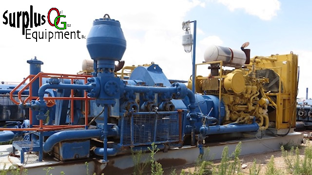
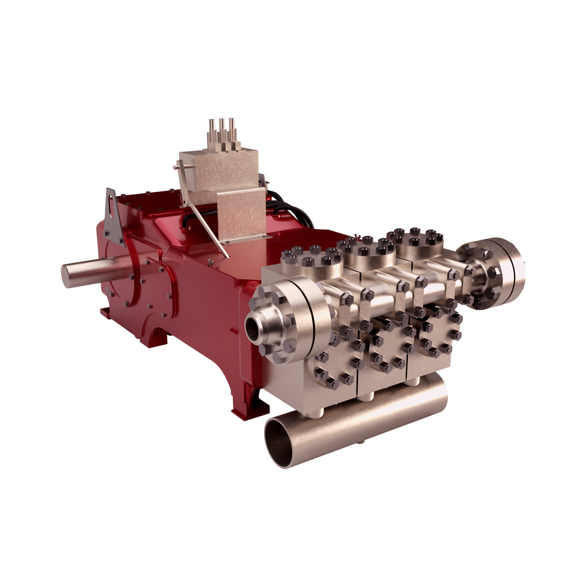
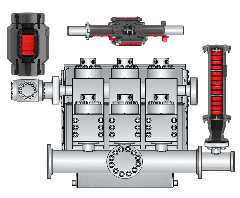
The 2,200-hp mud pump for offshore applications is a single-acting reciprocating triplex mud pump designed for high fluid flow rates, even at low operating speeds, and with a long stroke design. These features reduce the number of load reversals in critical components and increase the life of fluid end parts.
The pump’s critical components are strategically placed to make maintenance and inspection far easier and safer. The two-piece, quick-release piston rod lets you remove the piston without disturbing the liner, minimizing downtime when you’re replacing fluid parts.

A mud pump is a reciprocating piston or plunger device designed to pump drilling fluid under high pressures and volumes down the drill string of a drilling rig. The main functions of drilling fluid are to provide hydrostatic pressure to prevent formation fluids from entering and to stabilize the bore, to keep the drill bit cool and clean, to carry drill cuttings back out to the surface, and to suspend the drill cuttings while drilling is paused or during the pullback process.
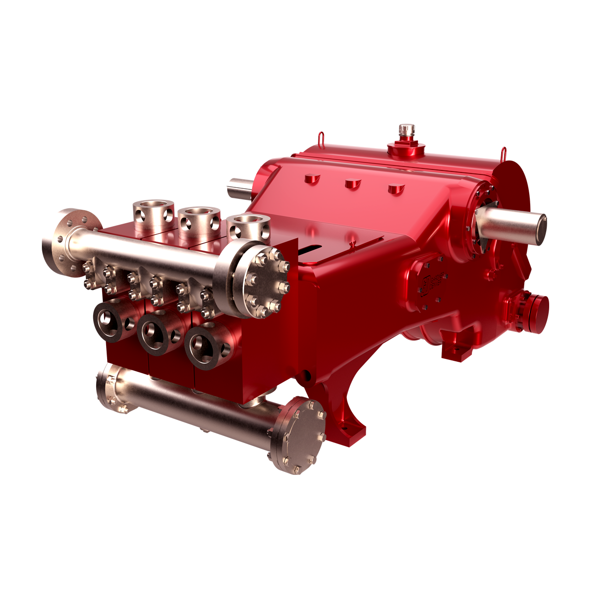
Mud pumps consist of two main sub-assemblies- the fluid end and the power end. The fluid end performs the pumping process with valves, pistons, and liners, or plungers and stuffing boxes- depending upon the type used. These components are considered expendables, and are designed to be easily replaced in the field. The power end contains the eccentric or crankshaft, along with the connecting rods, and cross heads/slides.
Tulsa Triplex is a Tulsa Rig Iron company. We manufacture pumps from 100 to 600 horsepower that are designed to be easily maintained and are capable of being completely rebuilt. Our pumps feature a smaller footprint and lighter weight than competing models, making them completely legal load size and weight in most instances. They are available as a bare pump, with chainbox, or a complete skidded package.
When choosing a size and type of mud pump for your drilling project, there are several factors to consider. These would include not only cost and size of pump that best fits your drilling rig, but also the diameter, depth and hole conditions you are drilling through. I know that this sounds like a lot to consider, but if you are set up the right way before the job starts, you will thank me later.
Recommended practice is to maintain a minimum of 100 to 150 feet per minute of uphole velocity for drill cuttings. Larger diameter wells for irrigation, agriculture or municipalities may violate this rule, because it may not be economically feasible to pump this much mud for the job. Uphole velocity is determined by the flow rate of the mud system, diameter of the borehole and the diameter of the drill pipe. There are many tools, including handbooks, rule of thumb, slide rule calculators and now apps on your handheld device, to calculate velocity. It is always good to remember the time it takes to get the cuttings off the bottom of the well. If you are drilling at 200 feet, then a 100-foot-per-minute velocity means that it would take two minutes to get the cuttings out of the hole. This is always a good reminder of what you are drilling through and how long ago it was that you drilled it. Ground conditions and rock formations are ever changing as you go deeper. Wouldn’t it be nice if they all remained the same?
Centrifugal-style mud pumps are very popular in our industry due to their size and weight, as well as flow rate capacity for an affordable price. There are many models and brands out there, and most of them are very good value. How does a centrifugal mud pump work? The rotation of the impeller accelerates the fluid into the volute or diffuser chamber. The added energy from the acceleration increases the velocity and pressure of the fluid. These pumps are known to be very inefficient. This means that it takes more energy to increase the flow and pressure of the fluid when compared to a piston-style pump. However, you have a significant advantage in flow rates from a centrifugal pump versus a piston pump. If you are drilling deeper wells with heavier cuttings, you will be forced at some point to use a piston-style mud pump. They have much higher efficiencies in transferring the input energy into flow and pressure, therefore resulting in much higher pressure capabilities.
Piston-style mud pumps utilize a piston or plunger that travels back and forth in a chamber known as a cylinder. These pumps are also called “positive displacement” pumps because they literally push the fluid forward. This fluid builds up pressure and forces a spring-loaded valve to open and allow the fluid to escape into the discharge piping of the pump and then down the borehole. Since the expansion process is much smaller (almost insignificant) compared to a centrifugal pump, there is much lower energy loss. Plunger-style pumps can develop upwards of 15,000 psi for well treatments and hydraulic fracturing. Centrifugal pumps, in comparison, usually operate below 300 psi. If you are comparing most drilling pumps, centrifugal pumps operate from 60 to 125 psi and piston pumps operate around 150 to 300 psi. There are many exceptions and special applications for drilling, but these numbers should cover 80 percent of all equipment operating out there.
The restriction of putting a piston-style mud pump onto drilling rigs has always been the physical size and weight to provide adequate flow and pressure to your drilling fluid. Because of this, the industry needed a new solution to this age-old issue.
As the senior design engineer for Ingersoll-Rand’s Deephole Drilling Business Unit, I had the distinct pleasure of working with him and incorporating his Centerline Mud Pump into our drilling rig platforms.
In the late ’90s — and perhaps even earlier — Ingersoll-Rand had tried several times to develop a hydraulic-driven mud pump that would last an acceptable life- and duty-cycle for a well drilling contractor. With all of our resources and design wisdom, we were unable to solve this problem. Not only did Miller provide a solution, thus saving the size and weight of a typical gear-driven mud pump, he also provided a new offering — a mono-cylinder mud pump. This double-acting piston pump provided as much mud flow and pressure as a standard 5 X 6 duplex pump with incredible size and weight savings.
The true innovation was providing the well driller a solution for their mud pump requirements that was the right size and weight to integrate into both existing and new drilling rigs. Regardless of drill rig manufacturer and hydraulic system design, Centerline has provided a mud pump integration on hundreds of customer’s drilling rigs. Both mono-cylinder and duplex-cylinder pumps can fit nicely on the deck, across the frame or even be configured for under-deck mounting. This would not be possible with conventional mud pump designs.
Centerline stuck with their original design through all of the typical trials and tribulations that come with a new product integration. Over the course of the first several years, Miller found out that even the best of the highest quality hydraulic cylinders, valves and seals were not truly what they were represented to be. He then set off on an endeavor to bring everything in-house and began manufacturing all of his own components, including hydraulic valves. This gave him complete control over the quality of components that go into the finished product.
The second generation design for the Centerline Mud Pump is expected later this year, and I believe it will be a true game changer for this industry. It also will open up the application to many other industries that require a heavier-duty cycle for a piston pump application.
A well-placed suction stabilizer can also prevent pump chatter. Pump chatter occurs when energy is exchanged between the quick opening and closing of the reciprocating pump’s valves and the hammer effect from the centrifugal pump. Pump isolation with suction stabilizers is achieved when the charge pumps are isolated from reciprocating pumps and vice versa. The results are a smooth flow of pumped media devoid of agitating energies present in the pumped fluid.
The drilling industry has roots dating back to the Han Dynasty in China. Improvements in rig power and equipment design have allowed for many advances in the way crude oil and natural gas are extracted from the ground. Diesel/electric oil drilling rigs can now drill wells more than 4 miles in depth. Drilling fluid, also called drilling mud, is used to help transfer the dirt or drill cuttings from the action of the drilling bit back to the surface for disposal. Drill cuttings can vary in shape and size depending on the formation or design of the drill bit used in the process.
Watch the video below to see how the EDDY Pump outperforms traditional pumps when it comes to high solids and high viscosity materials commonly found on oil rigs.
Solids control equipment including shakers, hydro-cyclones, and centrifuges are utilized to clean the drill cuttings from the drilling fluid, which then allows it to be reused and recirculated. The circuit includes the mixing of the drilling fluid in the rig tanks.
The drilling fluid is prepared to control fluid loss to the formation by the addition of chemicals or mineral agents. Commercial barite or other weighting agents are added to control the hydrostatic pressure exuded on the bottom of the well which controls formation pressures preventing fluid or gas intrusion into the wellbore.
The fluid is charged into high-pressure mud pumps which pump the drilling mud down the drill string and out through the bit nozzles cleaning the hole and lubricating the drill bit so the bit can cut efficiently through the formation. The bit is cooled by the fluid and moves up the space between the pipe and the hole which is called the annulus. The fluid imparts a thin, tough layer on the inside of the hole to protect against fluid loss which can cause differential sticking.
The fluid rises through the blowout preventers and down the flowline to the shale shakers. Shale shakers are equipped with fine screens that separate drill cutting particles as fine as 50-74 microns. Table salt is around 100 microns, so these are fine cuttings that are deposited into the half-round or cuttings catch tank. The drilling fluid is further cleaned with the hydro-cyclones and centrifuges and is pumped back to the mixing area of the mud tanks where the process repeats.
The drill cuttings contain a layer of drilling fluid on the surface of the cuttings. As the size of the drill cuttings gets smaller the surface area expands exponentially which can cause rheological property problems with the fluid. The fluid will dehydrate and may become too thick or viscous to pump so solids control and dilution are important to the entire drilling process.
One of the most expensive and troubling issues with drilling operations is the handling, processing, and circulation of drilling mud along with disposing of the unwanted drill cuttings. The drilling cuttings deposited in the half round tank and are typically removed with an excavator that must move the contents of the waste bin or roll-off box. The excavators are usually rented for this duty and the equipment charges can range from $200-300/day. Add in the cost for the day and night manpower and the real cost for a single excavator can be as much as $1800/day.
Offshore drilling rigs follow a similar process in which the mud is loaded into empty drums and held on the oil platform. When a certain number of filled drums is met, the drums are then loaded onto barges or vessels which take the drilling mud to the shore to unload and dispose of.
Oil field drilling operations produce a tremendous volume of drill cuttings that need both removal and management. In most cases, the site managers also need to separate the cuttings from the drilling fluids so they can reuse the fluids. Storing the cuttings provides a free source of stable fill material for finished wells, while other companies choose to send them off to specialty landfills. Regardless of the final destination or use for the cuttings, drilling and dredging operations must have the right high solids slurry pumps to move them for transport, storage, or on-site processing. Exploring the differences in the various drilling fluids, cutting complications, and processing options will reveal why the EDDY Pump is the best fit for the job.
The Eddy Pump is designed to move slurry with solid content as high as 70-80 % depending on the material. This is an ideal application for pumping drill cuttings. Drill cuttings from the primary shakers are typically 50% solids and 50% liquids. The Eddy Pump moves these fluids efficiently and because of the large volute chamber and the design of the geometric rotor, there is very little wear on the pump, ensuring long life and greatly reduced maintenance cost for the lifetime of the pump.
plumbed to sweep the bottom of the collection tank and the pump is recessed into a sump allowing for a relatively clean tank when the solids are removed. The Eddy Pump is sized to load a roll-off box in 10-12 minutes. The benefit is cuttings handling is quicker, easier, safer, and allows for pre-planning loading where the labor of the solids control technician is not monopolized by loading cuttings. Here, in the below image, we’re loading 4 waste roll-off bins which will allow the safe removal of cuttings without fear of the half-round catch tank running over.
Mud cleaning systems such as mud shaker pumps and bentonite slurry pumps move the material over screens and through dryers and centrifuges to retrieve even the finest bits of stone and silt. However, the pump operators must still get the raw slurry to the drill cuttings treatment area with a power main pump. Slurry pumps designed around the power of an Eddy current offer the best performance for transferring cuttings throughout a treatment system.
Options vary depending on whether the company plans to handle drill cuttings treatment on-site or transport the materials to a remote landfill or processing facility. If the plan is to deposit the cuttings in a landfill or a long-term storage container, it’s best to invest in a pump capable of depositing the material directly into transport vehicles. Most dredging operations rely on multiple expensive vacuum trucks, secondary pumps, and extra pieces of equipment.
Using an EDDY Pump will allow a project to eliminate the need for excavators/operators to load drill cuttings, substantially lowering both labor and heavy equipment costs. The EDDY Pump also allows a company to eliminate vacuum trucks once used for cleaning the mud system for displacing fluids. Since the pump transfers muds of all types at constant pressure and velocity throughout a system of practically any size, there’s little need for extra equipment for manual transfer or clean up on the dredge site.
The EDDY Pump can fill up a truck in only 10 minutes (compared to an hour) by using a mechanical means such as an excavator. For this reason, most companies can afford one piece of equipment that can replace half a dozen other units.
This application for the Eddy Pump has the potential to revolutionize the drilling industry. Moving the excavator out of the “back yard” (the area behind the rig from the living quarters) will make cuttings handling a breeze. Trucking can be easier scheduled during daylight hours saving on overtime and incidences of fatigued driving. Rig-site forklifts can move the roll-off boxes out of the staging area and into the pump loading area. The operator can save money on excavators rental, damages, and keep the technician operating the solids control equipment.
The EDDY Pump is ideal for drilling mud pump applications and can be connected directly onto the drilling rigs to pump the drilling mud at distances over a mile for disposal. This eliminates the need for costly vacuum trucks and also the manpower needed to mechanically move the drilling mud. The reasons why the EDDY Pump is capable of moving the drilling mud is due to the hydrodynamic principle that the pump creates, which is similar to the EDDY current of a tornado. This tornado motion allows for the higher viscosity and specific gravity pumping ability. This along with the large tolerance between the volute and the rotor allows for large objects like rock cuttings to pass through the pump without obstruction. The large tolerance of the EDDY Pump also enables the pump to last many times longer than centrifugal pumps without the need for extended downtime or replacement parts. The EDDY Pump is the lowest total life cycle pump on the market.
A mud pump is a reciprocating piston/plunger pump designed to circulate drilling fluid under high pressure (up to 7,500 psi (52,000 kPa)) down the drill string and back up the annulus. A duplex mud pump is an important part of the equipment used for oil well drilling.
Duplex mud pumps (two piston/plungers) have generally been replaced by the triplex pump, but are still common in developing countries. Two later developments are the hex pump with six vertical pistons/plungers, and various quintuplex’s with five horizontal piston/plungers. The advantages that Duplex mud pumps have over convention triplex pumps is a lower mud noise which assists with better Measurement while drilling and Logging while drilling decoding.
Use duplex mud pumps to make sure that the circulation of the mud being drilled or the supply of liquid reaches the bottom of the well from the mud cleaning system. Despite being older technology than the triplex mud pump, the duplex mud pumps can use either electricity or diesel, and maintenance is easy due to their binocular floating seals and safety valves.
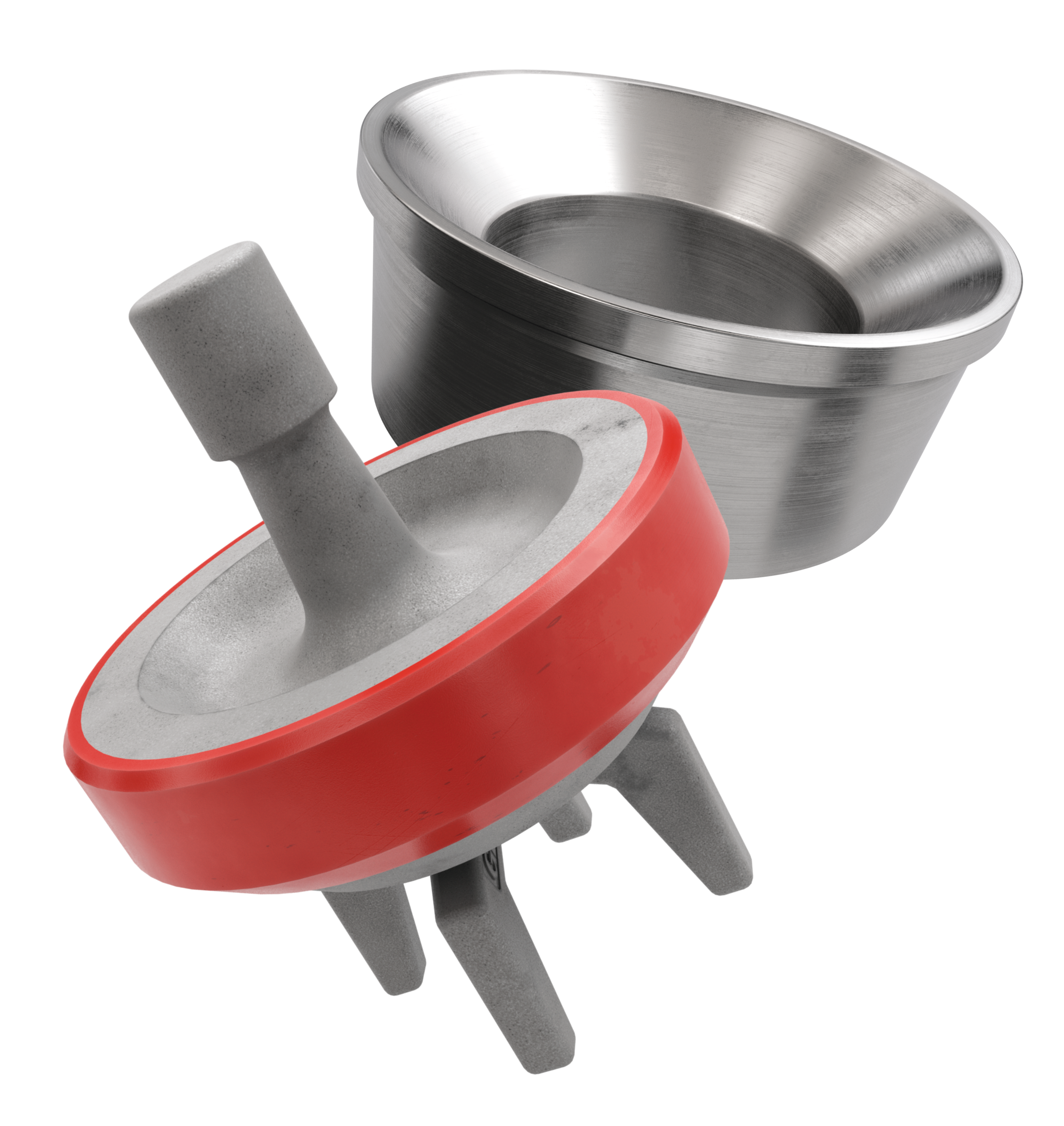
A mud pump is composed of many parts including mud pump liner, mud pump piston, modules, hydraulic seat pullers, and other parts. Parts of a mud pump:housing itself
Duplex pumps are used to provide a secondary means of fuel transfer in the event of a failure of the primary pump. Each pump in a duplex set is sized to meet the full flow requirements of the system. Pump controllers can be set for any of the following common operating modes:Lead / Lag (Primary / Secondary): The lead (primary) pump is selected by the user and the lag (secondary pump operates when a failure of the primary pump is detected.
Alternating: Operates per Lead / Lag (Primary / Secondary) except that the operating pump and lead / lag status alternate on consecutive starts. A variation is to alternate the pumps based on the operating time (hour meter) of the lead pump.
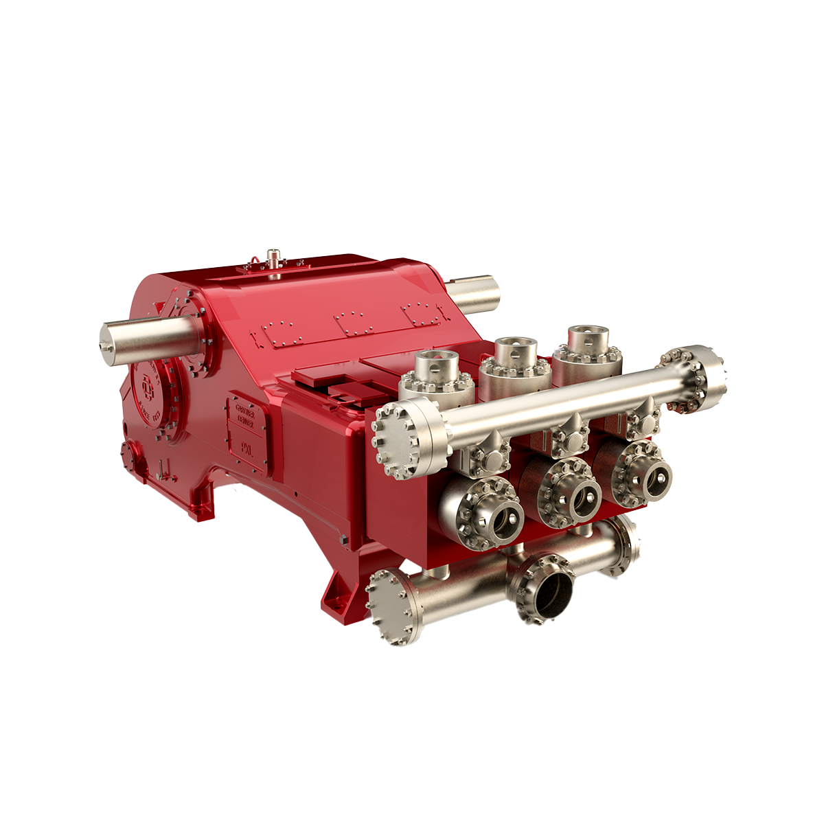
The NOV FC-1600 Triplex Mud Pump is made of rugged Fabriform construction and designed for optimum performance under extreme drilling conditions. It is compact and occupies less space, yet delivers unequaled performance. The pumps are backed by several decades of design and manufacturing experience, and are considered leaders in the field.
NOV FC-1600 Triplex Mud Pump is conservatively rated at relatively low rpm. This reduces the number of load reversals in heavily stressed components and increases the life of the fluid end parts through conservative speeds and valve operation.
The NOV FC-1600 Triplex Mud Pump design provides an inherently balanced assembly. No additional counterbalancing is required for smooth operation. No inertia forces are transmitted to the pumps’ mountings.
A Triplex Mud Pump sometimes referred to as a drilling mud pump or mud drilling pump. NOV FC-1600 Triplex Mud Pump is a reciprocating piston/plunger pump designed to circulate drilling fluid under high pressure (up to 7,500 psi) down the drill string and back up the annulus. A mud pump is an important part of the equipment used for oil well drilling.

Drilling Fluids, also called drilling mud, in petroleum engineering, a heavy, viscous fluid mixture that is used in oil and gas drilling operations to carry rock cuttings to the surface and also to lubricate and cool the drill bit. The drilling mud, by hydrostatic pressure, also helps prevent the collapse of unstable strata into the borehole and the intrusion of water from water-bearing strata that may be encountered.
The drilling fluid system is commonly known as the “mud system”. It is the single component of the well-construction process that remains in contact with the wellbore throughout the entire drilling operation. Drilling fluid systems are designed and formulated to perform efficiently under expected wellbore conditions. Advances in drilling fluid technology have made it possible to implement a cost-effective, fit-for-purpose system for each interval in the well-construction process.
The active drilling fluid system comprises a volume of fluid that is pumped with specially designed mud pumps from the surface pits. It travels through the drill string exiting at the bit, up the annular space in the wellbore, and back to the surface for solids removal and maintenance treatments as needed. The capacity of the surface system usually is determined by the rig size, and rig selection is determined by the well design.
For example, the active drilling-fluid volume on a deep water well might be several thousand barrels. Much of that volume is required to fill the long drilling riser that connects the rig floor to the seafloor. By contrast, a shallow well on land might only require a few hundred barrels of fluid to reach its objective.
There are many types of drilling fluids are used on a day-to-day basis. Some wells require that different types be used at different parts in the hole, or that some types be used in combination with others. The various types of the fluid generally fall into a few broad categories.
The most basic water-based mud systems begin with water, then clays and other chemicals are incorporated into the water to create a homogeneous blend resembling something between chocolate milk and a malt (depending on viscosity).
The fluid is the mud in which water is the continuous phase. This is the most common drilling mud used in oil drilling. The following designations are normally used to define the classifications of water base drilling fluid.
Oil-based mud is a mud where the base fluid is a petroleum product such as diesel fuel. Oil-based muds are useful for many reasons, such as increasing the lubricity, enhanced the shale inhibition, greater cleaning abilities with less viscosity, and the oil-based muds also withstand greater heat without breaking down.
There are 2 types of oil-based muds which are Invert emulsion oil muds and Pseudo oil based muds.If the amounts of water are more than 5 %. It will become water-in-oil emulsion or Invert emulsion.
Synthetic-based fluid is a mud where the base fluid is a synthetic oil. This is most often used on offshore rigs because it has the properties of an oil-based mud, but the toxicity of the fluid fumes are much less than an oil-based fluid. Synthetic-based fluid poses the same environmental and analysis problems as oil-based fluid.
Water-based drilling mud most commonly consists of Bentonite clay (gel) with additives such as Barium sulfate (Barite), Calcium carbonate (chalk) or Hematite. Various thickeners are used to influence the viscosity of the fluid, e.g. xanthan gum, guar gum, glycol, or starch. Some other common additives including lubricants, shale inhibitors, and the fluid loss additives.
A weighting agent such as Barite is added to increase the overall density of the drilling fluids. Sufficient bottom hole pressure can be maintained thereby preventing an unwanted (and often dangerous) influx of formation fluids. Using of silica and clay nanoparticles for high pressure and high temperature help to get an Invert emulsion based muds and to observed their positive effect on the rheology of the drilling mud.
Positive displacements pumps are generally used on drilling rigs to pump high pressure and high volume of drilling fluids throughout a drilling system. There are several reasons why the positive displacement mud pumps are used on the rigs.
The duplex pumps (Figure 1) have two cylinders with double acting. It means that pistons move back and take in drilling mud through open intake valve and other sides of the same pistons, the pistons push mud out through the discharge valves.
When the piston rod is moved forward, one of intake valves is lift to allow fluid to come in and one of the discharge valve is pushed up therefore the drilling mud is pumped out of the pump (Figure 2).
On the other hand, when the piston rod is moved backward drilling fluid is still pumped. The other intake and discharge valve will be opened (Figure 3).
The triplex pumps have three cylinders with single acting. The pistons are moved back and pull in drilling mud through open intake valves. When the pistons are moved forward and the drilling fluid is pushed out through open discharge valves.
On the contrary when the piston rods are moved backward, the intake valve are opened allowing drilling fluid coming into the pump (Figure 6). This video below shows how a triplex mud pump works.
Because each pump has power rating limit as 1600 hp, this will limit capability of pump. It means that you cannot pump at high rate and high pressure over what the pump can do. Use of a small liner will increase discharge pressure however the flow rate is reduces. Conversely, if a bigger liner is used to deliver more flow rate, maximum pump pressure will decrease.
As you can see, you can have 7500 psi with 4.5” liner but the maximum flow rate is only 297 GPM. If the biggest size of liner (7.25”) is used, the pump pressure is only 3200 psi.
Finally, we hope that this article would give you more understanding about the general idea of drilling mud pumps. Please feel free to add more comments.

The water-based mud in the wellbore from the previous hole section is displaced and replaced with POBM drilling fluid. The first step is to lower the viscosity and gel strength of the water-based mud. The suggested method is to dilute the fluid with water to obtain a low rheology (Patel [3]). The optimal thinning of the water-based mud will dictate how easy the mud will be displaced out of the hole. The spacer is pumped first, followed by the POBM mud at maximum pump rate to get the mud in the annulus moving (Table 8).
After drilling and prior to running completion hardware, the fluid in the borehole is often displaced to a water-based completion fluid, usually a solution of various salts. During this displacement, chemical washes and viscous spacers are placed in the solution to make surfaces water- wet, while helping to remove oil mud and residual oil-wet material from the borehole (Ali et al. [4]).
The viscosity and gel strengths of the POBM are low prior to displacement. The suggested method was to dilute the fluid with premix, base fluid or a thinner to obtain the low rheology if this is necessary. The optimal thinning of the POBM fluid will dictate how easy the mud will be displaced out of the hole.

Electric Trash Pumps, sometimes referred to as Mud Pumps, can save on cost when power is available, making an electric pump a good choice for long-term pump rental. Electric Trash Pumps run quieter, thus being an ideal solution when noise is a concern. Rental Trash Pumps work well for pumping water containing large amounts of particulate and debris. Applications where a Mud Pump is well suited are sewer bypass systems and digester tank pumping, or pumping drillers mud at oil and gas drilling sites.
AfghanistanAlbaniaAlgeriaAmerican SamoaAndorraAngolaAnguillaAntarcticaAntigua and BarbudaArgentinaArmeniaArubaAustraliaAustriaAzerbaijanBahamasBahrainBangladeshBarbadosBelarusBelgiumBelizeBeninBermudaBhutanBoliviaBonaire, Sint Eustatius and SabaBosnia and HerzegovinaBotswanaBouvet IslandBrazilBritish Indian Ocean TerritoryBrunei DarussalamBulgariaBurkina FasoBurundiCabo VerdeCambodiaCameroonCanadaCayman IslandsCentral African RepublicChadChileChinaChristmas IslandCocos IslandsColombiaComorosCongoCongo, Democratic Republic of theCook IslandsCosta RicaCroatiaCubaCuraçaoCyprusCzechiaCôte d"IvoireDenmarkDjiboutiDominicaDominican RepublicEcuadorEgyptEl SalvadorEquatorial GuineaEritreaEstoniaEswatiniEthiopiaFalkland IslandsFaroe IslandsFijiFinlandFranceFrench GuianaFrench PolynesiaFrench Southern TerritoriesGabonGambiaGeorgiaGermanyGhanaGibraltarGreeceGreenlandGrenadaGuadeloupeGuamGuatemalaGuernseyGuineaGuinea-BissauGuyanaHaitiHeard Island and McDonald IslandsHoly SeeHondurasHong KongHungaryIcelandIndiaIndonesiaIranIraqIrelandIsle of ManIsraelItalyJamaicaJapanJerseyJordanKazakhstanKenyaKiribatiKorea, Democratic People"s Republic ofKorea, Republic ofKuwaitKyrgyzstanLao People"s Democratic RepublicLatviaLebanonLesothoLiberiaLibyaLiechtensteinLithuaniaLuxembourgMacaoMadagascarMalawiMalaysiaMaldivesMaliMaltaMarshall IslandsMartiniqueMauritaniaMauritiusMayotteMexicoMicronesiaMoldovaMonacoMongoliaMontenegroMontserratMoroccoMozambiqueMyanmarNamibiaNauruNepalNetherlandsNew CaledoniaNew ZealandNicaraguaNigerNigeriaNiueNorfolk IslandNorth MacedoniaNorthern Mariana IslandsNorwayOmanPakistanPalauPalestine, State ofPanamaPapua New GuineaParaguayPeruPhilippinesPitcairnPolandPortugalPuerto RicoQatarRomaniaRussian FederationRwandaRéunionSaint BarthélemySaint Helena, Ascension and Tristan da CunhaSaint Kitts and NevisSaint LuciaSaint MartinSaint Pierre and MiquelonSaint Vincent and the GrenadinesSamoaSan MarinoSao Tome and PrincipeSaudi ArabiaSenegalSerbiaSeychellesSierra LeoneSingaporeSint MaartenSlovakiaSloveniaSolomon IslandsSomaliaSouth AfricaSouth Georgia and the South Sandwich IslandsSouth SudanSpainSri LankaSudanSurinameSvalbard and Jan MayenSwedenSwitzerlandSyria Arab RepublicTaiwanTajikistanTanzania, the United Republic ofThailandTimor-LesteTogoTokelauTongaTrinidad and TobagoTunisiaTurkmenistanTurks and Caicos IslandsTuvaluTürkiyeUS Minor Outlying IslandsUgandaUkraineUnited Arab EmiratesUnited KingdomUnited StatesUruguayUzbekistanVanuatuVenezuelaViet NamVirgin Islands, BritishVirgin Islands, U.S.Wallis and FutunaWestern SaharaYemenZambiaZimbabweÅland Islands
We design and manufacture robust, functional, reliable high pressure pumping equipment for mud injection applications around the world. Every Calder Waste Injection unit incorporates the proven inherent attributes of quality and reliability whilst matching individual installation requirements. The well service mud pumps are designed to operate over a wide range of flows and pressures for the injection of seawater and slurries consisting of drill cuttings, drilling muds and sand into subsea strata as demanded by the offshore drilling industry worldwide.
We have the experience and skills to engineer a cost-effective solution to your mud pump requirements in a range of operating environments utilising the best engineering practices, and designing the system to be either diesel, electric or hydraulically powered.
In selecting the most suitable type of drilling fluid, many different factors must be considered. Overall what is required is a mud system that gives the lowest overall cost of drilling each hole section, except for through the reservoir. The direct cost of the fluid itself (the cost per barrel of mud) is but one component of this overall cost. If serious hole problems occur because the mud was not optimized for the formations in an effort to “save money,” obviously much more money will be spent than would have been saved on the mud bill.
When drilling through the reservoir, the key is to minimize damaging reactions between the mud and the reservoir that lower the production possible from the well. If a well loses only 10% of its potential production rate due to avoidable damage from the mud, the cost to the operator in lost profit over the full life of the well will be large.
Mud cost must be considered but only to choose between technically suitable systems. Therefore what should happen is that for each hole system, all technically suitable alternatives should be defined and then the cost of each can be compared for a final choice.
Physical, rheological, and chemical characteristics can be defined for each hole section, leading to a list of requirements for the mud system of choice.
Density. Primary control of downhole pressures is obtained with a mud of such density as to exert a greater hydrostatic pressure on the formation than exists within formation pores.
The lower safe limit of mud density is calculated by the density to balance formation pore pressure, plus a small additional amount as a safety margin.
Some formations require a minimum hydrostatic pressure to keep them stable. When a hole is drilled through a rock in the ground, the stresses in the surrounding rock will tend to push the rock into the hole. If mud hydrostatic pressure is kept high enough, it pushes back against the rock and so supports it. The required density gradient is likely to be something greater than that required to maintain well control.
Losses or formation breakdown may be induced if the hydrostatic pressure plus circulating pressure losses exceed formation strength. Circulating pressure losses refer to the pressure necessary to force fluid to flow along a pipe or annulus. The pressure at the bottom of the well while circulating equals mud hydrostatic pressure plus the pressure required to force the mud to flow up the annulus. This extra pressure imposed while circulating along the open hole can be enough to fracture weak formations in some cases.
Some shales contain tiny fractures. When mud or filtrate is forced into the fractures, this lubricates the fracture faces. It also changes the stress regime in the near-wellbore zone. The wellbore will become unstable, and chunks of the shale will fall off into the well. (As explained previously, the filtrate is the liquid part of the mud. When mud is forced against a permeable zone, the solids in the mud form a plaster or “wall cake” against the formation face. Some of the liquid fraction will filter through this cake and into the formation. This liquid fraction [water plus dissolved salts] is called filtrate.)
Fluid loss. The fluid loss property of a mud indicates how well the mud forms a seal against permeable formations. To test fluid loss, a sample of mud is placed inside a chamber, which has a standard filter at the bottom. The chamber is closed and 100 psi is exerted on the mud sample. Filtrate is squeezed through the filter into a container below, and wall cake builds up on the filter. The standard test measures the amount of filtrate collected in 30 minutes, with the thickness of the filter cake given in 1/32nds of an inch or in millimeters. A description of the filter cake might also be made, using descriptions such as hard, soft, tough, rubbery, firm, etc. Figure 1. shows a filter press, which is used to test the fluid loss.
A high fluid loss mud will build up a thicker, stickier wall cake, which is likely to lead to problems such as pipe sticking in the hole. Ideally the mud should build up a thin, tough, and impermeable cake fairly quickly.
The test for fluid loss is a comparative test. It does not indicate how much filtrate will actually be lost to the formation, or how thick the filter cake might actually become. These things depend on many factors, such as the actual pressure overbalance, the permeability of the downhole formation, and the effects of mud flow or pipe movement eroding the filter cake.
Sand content. Sand is normally the most abrasive solid present in the mud, and a high sand content will increase wear on pumps, valves, and other equipment. However, all solids in the mud will contribute to mud abrasiveness. Sand content should be kept as low as possible by using the solids control equipment properly. The sand content is measured by passing a fixed volume of mud through a 200-mesh sieve into a marked glass container. The sand sits in the bottom, and the sand content is measured directly from the marks.
Mud rheology. Rheology is the science of the deformation and flow of fluids. When discussing the rheology of fluids in the well (mud, cement, or brines), what is of interest is the relationship between how fast the fluid flows and the pressure required to maintain that flow rate (either in the pipe or in the annulus). The relationships between these properties will affect circulating pressures, surge and swab pressures, and hole cleaning ability. Surge and swab pressures occur when the drillstring is lowered in the hole and fluid is displaced upwards. This imposes temporary extra pressure on the hole and is called surge pressure. When the drillstring is lifted upwards, fluid has to flow downwards as a pressure drop or suction is created by the withdrawal of the steel volume. This causes a temporary pressure reduction on the hole and is called swab pressure. Hole cleaning ability refers to the ability of a drilling fluid to lift cuttings out of the hole at a certain flow rate. This ability is related to the fluid density and rheology.
To fully specify a drilling fluid that must perform specific functions, the required rheology must also be defined. The rheology not only affects the relationship between flow rate and pressure it also affects the flow rates at which the flow regimes change.
The chemical characteristics of the mud are mostly determined by wellbore stability considerations of the formations drilled through in a particular hole section. In addition, the mud should not damage the reservoir (reduce permeability), or at least damage done to reservoir permeability should be capable of being repaired (e.g., by using acid to remove plugging solids) or bypassed (explosive perforations penetrating through the damaged zone).
Reactive shales. Many hole problems are caused by incompatibility between water and shales. This may be solved by using oil/water emulsion muds (with oil as the continuous phase) or 100% oil muds. This isolates water from the shales and so prevents hydration. Oil muds are becoming increasingly difficult to use in some areas due to environmental concerns and resulting government regulation changes. These muds are also expensive.
Water-based muds may use various chemical inhibitors to control reactive shales, such as potassium chloride (KCl). KCl works by swapping places with sodium ions in the clay structure. As the potassium ion is smaller than the sodium ion, this causes the clay structure to shrink rather than expand.
Salts. A nonsalt-saturated, water-based mud will leach out salt formations, causing extreme hole enlargement and possible cementing problems. This can be addressed by using either salt-saturated water mud or an oil-based mud.
Reservoir damage.Mud filtrate can be extremely damaging to formation fluids. There are two areas of particular concern: pollution of water sources and reduced productivity of the pay zone. There are two approaches in these cases, and they may be used together. The first is to prevent filtrate invasion by using additives to plug off pore throats where the formation is exposed. The second approach is to use a mud that has a nondamaging filtrate. In the pay zone, productivity damage from filtrate may occur in several ways:
Corrosion of downhole steel components. Tools and tubulars used in drilling, casing, and completing the well can be subject to corrosion by the mud. For most casing strings, mud is left in the annulus after the cement job, which will remain for the life of the well. Mud properties may change over time due to bacteriological action. This can produce H2S (especially when the mud contains organic additives) or low pH levels. Oil muds produce oil wetting of metal surfaces and will protect against CO2,H2S, and H2O corrosion.
Hydrogen sulfide–related problems. Hydrogen sulfide (H2S) may enter the mud from a permeable formation, either as a kick or from within drilled cuttings. Apart from the extreme toxicity of this gas, it causes hydrogen embrittlement of most steels, which degrades tensile strength. If H2S is anticipated, an excess level of lime in the mud will help. The alkaline lime will help neutralize the acidic H2S. The reaction forms active sulfides such as CaS or Ca(HS)2, which will liberate H2S if exposed to a mild acid. Once H2S has been identified in the mud system, zinc oxide (ZnO) may be added. ZnO is an effective scavenger of H2S and active sulfide salts. This reacts to form stable zinc sulfide. It is not recommended to use ZnO before H2S is identified, as it will mask a slow entry of H2S into the system. Recommended concentration of ZnO is around 2 lb for each barrel of mud.

The purpose of this article is to present some guidelines and simplified techniques to size pumps and piping typically used in mud systems. If unusual circumstances exist such as unusually long or complicated pipe runs or if very heavy or viscous drilling muds are used, a qualified engineer should analyze the system in detail and calculate an exact solution.
To write about pumps, one must use words that are known and well understood. For example, the label on the lefthand side of any centrifugal pump curve is Total Head Feet. What does this mean?
Total Head remains constant for a particular pump operated at a constant speed regardless of the fluid being pumped. However, a pump’s pressure will increase as the fluid density (mud weight) increases according to the following relationship:
Note that the pump pressure almost doubled. It follows that the required pump horsepower has increased by the same percentage. If the pump required 50 HP for water service, it will require the following horsepower for 16 lb/gal mud:
To summarize, a pump’s Total Head remains constant for any fluid pumped, only the pump pressure and pump horsepower will change. Therefore, a pump motor must be sized according to the heaviest weight mud to be pumped.
In our example problem, the required desilter pressure head is 75 ft. for any mud weight. However, the pressure would be 30.3 PSIG for water or 43.6 PSIG for 12 lb mud or 58.1 PSIG for 16 lb mud. A good rule of thumb is that the required pressure (PSIG) equals 4 times the mud weight (12 LB/GAL x 4 = 48 PSIG).
Determine the required pressure head and flow rate. If the pump is to supply a device such as a mud mixing hopper or a desilter, consult the manufacturer’s information or sales representative to determine the optimum flow rate and pressure head required at the device. (On devices like desilters the pressure head losses downstream of the device are considered negligible and are usually disregarded.)
Select the basic pump to pump the desired flow rate. Its best to refer to a manufacturer’s pump curve for your particular pump. (See example – Figure 3).
The pump’s impeller may be machined to a smaller diameter to reduce its pressure for a given application. Refer to the manufacturer’s pump curves or manufacturer’s representative to determine the proper impeller diameter. Excessive pressure and flow should be avoided for the following reasons:
The pump must produce more than 75 FT-HD at the pump if 75 FT-HD is to be available at the desilter inlet and the pump’s capacity must be at least 800 GPM. Therefore, we should consider using one of the following pumps from the above list: 4″ x 5″ Pump 1750 RPM – 1000 GPM at 160 FT-HD; or 5″ x 6″ Pump 1750 RPM – 1200 GPM at 160 FT-HD.
The pump suction and discharge piping is generally the same diameter as the pump flange diameters. The resulting fluid velocities will then be within the recommended ranges of 4 to 10 FT/SEC for suction lines and 4 to 12 FT/
SEC for discharge lines. Circumstances may dictate that other pipe diameters be used, but remember to try to stay within the above velocity guidelines. Smaller pump discharge piping will create larger pressure drops in the piping
and the pump may not be able to pump the required amount of fluid. (For example, don’t use a 4″ discharge pipe on a 6″ x 8″ pump and expect the pump’s full fluid flow.)
6″ pipe may be used for the suction pipe since it is relatively short and straight and the pump suction is always flooded. 6″ pipe is fully acceptable for the discharge pipe and is a good choice since the desired header is probably 6″ pipe.
8″ pipe may be used for the suction pipe (V = 5.13 FT/SEC) since V is still greater than 4 FT/SEC. 8″ pipe would be preferred if the suction is long or the suction pit fluid level is low with respect to the pump.


 8613371530291