
drilling mud pump motor free sample

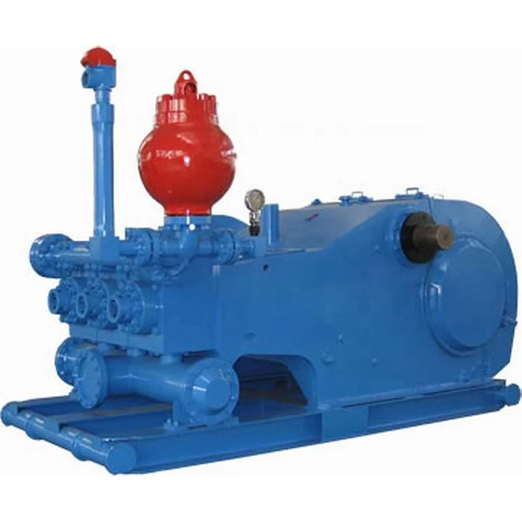
The 2,200-hp mud pump for offshore applications is a single-acting reciprocating triplex mud pump designed for high fluid flow rates, even at low operating speeds, and with a long stroke design. These features reduce the number of load reversals in critical components and increase the life of fluid end parts.
The pump’s critical components are strategically placed to make maintenance and inspection far easier and safer. The two-piece, quick-release piston rod lets you remove the piston without disturbing the liner, minimizing downtime when you’re replacing fluid parts.
Explore a wide variety of dc mud pump motor on Alibaba.com and enjoy exquisite deals. The machines help maintain drilling mud circulation throughout the project. There are many models and brands available, each with outstanding value. These dc mud pump motor are efficient, durable, and completely waterproof. They are designed to lift water and mud with efficiency without using much energy or taking a lot of space.
The primary advantage of these dc mud pump motor is that they can raise water from greater depths. With the fast-changing technology, purchase machines that come with the best technology for optimum results. They should be well adapted to the overall configuration of the installation to perform various operations. Hence, quality products are needed for more efficiency and enjoyment of the machines" full life expectancy.
Alibaba.com offers a wide selection of products with innovative features. The products are designed for a wide range of flow rates that differ by brand. They provide cost-effective options catering to different consumer needs. When choosing the right dc mud pump motor for the drilling project, consider factors such as size, shape, and machine cost. More powerful tools are needed when dealing with large projects such as agriculture or irrigation.
Alibaba.com provides a wide range of dc mud pump motor to suit different tastes and budgets. The site has a large assortment of products from major suppliers on the market. The products are made of durable materials to avoid corrosion and premature wear during operations. The range of products and brands on the site assures quality and good value for money.
Explore a wide variety of mud motor water pump on Alibaba.com and enjoy exquisite deals. The machines help maintain drilling mud circulation throughout the project. There are many models and brands available, each with outstanding value. These mud motor water pump are efficient, durable, and completely waterproof. They are designed to lift water and mud with efficiency without using much energy or taking a lot of space.
The primary advantage of these mud motor water pump is that they can raise water from greater depths. With the fast-changing technology, purchase machines that come with the best technology for optimum results. They should be well adapted to the overall configuration of the installation to perform various operations. Hence, quality products are needed for more efficiency and enjoyment of the machines" full life expectancy.
Alibaba.com offers a wide selection of products with innovative features. The products are designed for a wide range of flow rates that differ by brand. They provide cost-effective options catering to different consumer needs. When choosing the right mud motor water pump for the drilling project, consider factors such as size, shape, and machine cost. More powerful tools are needed when dealing with large projects such as agriculture or irrigation.
Alibaba.com provides a wide range of mud motor water pump to suit different tastes and budgets. The site has a large assortment of products from major suppliers on the market. The products are made of durable materials to avoid corrosion and premature wear during operations. The range of products and brands on the site assures quality and good value for money.

The Adtech Downhole Drilling Motor is a positive displacement hydraulic motor/pump powered by drilling rig mud or water. When the fluid is pumped through the tool the bit is turned at a speed proportional to the flow and remains relatively constant regardless of the load or developed horsepower. As weight is added to the motor and the bit start drilling the standpipe pressure will increase in direct proportion to the torque generated. This serves as a built-in indicator as to how the motor is performing, even if wall drag prevents an accurate response of the rig weight indicator.
Slow Speed: The motor operates at a speed more compatible with roller bits. This significantly lengthens bit life with increased on bottom time and fewer round trips.
Oil Filled - Sealed Bearing Section: Pressure compensated bearing section provides long seal life and more dependable bearing operation. Specialized Designs Adtech motors are specifically designed for the HDD market with advanced sealed bearing sections, oversized bearing packs and thick-walled stators
Design: All housings of the Adtech motor are tightened with controlled torque (breakout machines) and are locked to minimize accidental backoffs. Prior to shipment out to the field, each tool is thoroughly inspected and tested on our mud pump testing station to guarantee long, trouble-free operation.
Motor Section: The power section (rotor and stator) is the heart of the Adtech motor. The rotor is double plated with hard chrome to protect it from well bore fluids and abrasion. The stator is molded with an elastomer rubber that also resists the drilling environment. The rotor/stator configuration, stage length, and number of stages determine the speed and torque ratings of the motor. All motor parts are manufactured here at Adtech"s facility including the forming of the rotor and the injection of the rubber into the stator.
The Adtech Downhole Drilling Motor is an easy tool to operate provided it is operated within its design specifications. It should be noted that the specific use of any tool may vary from operator to operator and experience will show the most efficient and safe procedure to follow. It is recommended that a float be run above the tool to keep the bit or other parts of the tool from plugging. Though the tool is built to withstand normal wear and tear, care should be taken while running to depth since damage can occur from hitting bridges, casing shoes, junk or other obstructions in a hole. To run past these tight spots the motor should be operated at its normal speed. If a bent sub is used, the drillpipe (and motor) should be slowly rotated to prevent accidental side tracking of the main hole. As a guide, however the following steps are recommended for routine drilling operations:
Since the speed of the motor is proportional to the fluid volume it is important that the flow rate be accurately set and maintained throughout the drilling operation. When the tool has reached the correct depth and is off bottom, the flow should be set. This will establish the off bottom or no-load pressure the driller sees at the standpipe.
After proper cleaning of the hole, tool orientation, if applicable, should be performed before drilling ahead. As with all downhole drilling motors, the Adtech motor imparts a left-hand torque (tending to tighten the tool joints) into the string above/before the tool. This torque is equal and opposite to the torque generated at the bit while drilling. As weight is slowly added to the motor and the bit starts drilling, the pressure will increase in direct proportion to the torque generated. Assuming everything but the weight on the bit remains constant in any specific drilling situation, the rig pressure gage will be an indicator of the weight on the bit and especially useful piece of telemetry where wall drag prevents an accurate response of the rig weight indicator. If the rig pressure gage does not respond as indicated and the tool does not drill off as predicted, see the section titled Trouble-Shooting. As initial drilling commences a little difficulty may be encountered in getting the tool to drill smoothly. This is due to the bit seating in on the previously drilled formation and will disappear in a short time.
To obtain the best performance from the Adtech Downhole Drilling Motor, it is necessary to use the tool within the specifications and limitations for which it is designed. Care should be used in selecting the right size tool for the right job. Due to the high torque capability of the motor, there may be a tendency to use a tool that is really too small for the job resulting in unsatisfactory performance due to the flow and strength limitations. Tabled below are the general specifications of the motors that are now or soon will become available. These specifications will change from time to time as improvements are incorporated.
Sometimes due to rig or hole conditions it may be necessary to operate with flow rates other than that recommended in the table. Since the listed operating speed of the motor is directly proportional to the flow its change should also be considered. The output torque of the motor is, however, generally independent of the flow and therefore little change of the allowable weight on the bit should be realized. Changing the flow will, of course, change the bit hydraulic horsepower and this coupled with the change in bit speed will in many instances affect the drilling rate of penetration. The tool should never be operated more than 15% above the designed operating flow due to the high pressure drop and flow velocities through the tool. Also operating more than 30% below the recommended flow will result in a lower speed and therefore a decreased rate of penetration and performance. If it is desired to operate below the designed flow, it is recommended that the motor first be started with the designed flow and then adjusted back as required.
When drilling is first started, it may take 10-15 minutes for the bit to seat in the previously drilled formation before drilling will proceed smoothly. However, if the motor does not take pressure and drill off as predicted, the following outline may help in correcting the situation. It should be noted though, that most operators have acquired years of experience with drilling motors and have possibly seen every type of malfunction. In each case the operator may use his own particular trick to remedy the problem:
Is the motor sanded-up? An especially dirty hole of faulty float valve could have allowed solids to settle within the motor causing the drilling fluid to channel rather than turn the motor. Continuous pumping (15 minutes maximum) will sometimes correct such a condition. Also during this time slow rotation of the pipe (to the right) while gently tagging bottom will sometimes free the motor.
If none of the above (or other) corrective actions prove unsuccessful, it will be necessary to trip the tool from the hole. While tripping check for drill pipe and drill collar for washouts to be sure calculated flow was actually getting to the tool. Surface check the tool by pumping through at normal flow rates and watch for normal rotation. If the tool does not rotate pump through for 15 minutes to see if it clears itself. If the motor turns at about half its normal speed check the bypass valve again to be sure that it is actuating freely. Check for anything unusual, as for example, pieces of metal or rubber trapped in the bit, a bent bit sub, etc.
The bearing section of the Adtech Downhole Drilling Motor has been completely filled with oil at the factory and should not normally require any additional service at location. However, for unusually long runs the oil level should be checked in the field to be sure the bearings are operating with the proper amount of lubrication. More information on checking the oil level may be obtained from your Adtech representative.
In operating the Adtech Downhole Drilling Motor, the most important items to watch to assure a successful run are the motor and system hydraulics. It cannot be overemphasized that reliable, high performance will be obtained by close attention to the proper hydraulic requirements. If desired, the Adtech motor can run with diamond bits with one important note. The pressure drop across a diamond bit is caused by friction as the drilling fluid flows between the bit surface and the formation. This pressure drop will vary as the bit is put on bottom and increase as the fluid must pass through the small area between the fluid-courses on the bit and hole itself. In diamond drilling, it should also be noted that the difference in standpipe pressure between drilling and rotating off bottom is due to the pressure increase across the bit and the normal pressure required to produce power by the motor. By subtracting the designed bit pressure drop, the actual motor pressure increase associated with its torque generation can be determined.
The Adtech motor, being a positive displacement motor, will run at a specific speed (RPM) for a specific volume (gal/min.) throughout. The required circulation rate as discussed under Specifications should be established prior to drilling and maintained throughout the drilling program for optimum tool performance. For duplex and triplex piston pumps, the flow rate depends on the length of the pump stroke, liner size, number of strokes per minute, and efficiency. For easy reference, the circulation rate for various sizes of pumps is shown in Appendixes F and G. For duplex pumps, these tables were prepared using 95% efficiency for under 40 strokes per minute and 90% efficiency for over 40 strokes per minute. The triplex pump information is shown at 100% efficiency.
The Adtech motor is designed to effectively handle most drilling fluids including lost circulation material. However, since the long term performance of the motor depends so heavily on the mud as its source of power more attention will be given to it here. Regular and complete testing of the mud is important not only to the prevention of damage to the motor but also to the success of drilling and maintaining the hole condition as well.
Particular attention should be given to the following items: Lost Circulation Material As a general rule anything the rig pump can handle can also be handled by the drilling motor. Care should be exercised however in adding these materials to the mud system so that the system is not slugged with large quantities at one time. These could become lodged within the motor or bit passageways. Also it is advisable to run the rig pumps with screens to avoid extra large debris from entering the system. Rags and tools accidentally dropped down the circulating system will severely plug and damage drilling motor.
Just like sand and abrasive solids will damage the rig surface equipment the drilling motor will likewise be adversely affected. If possible, desanders should always be used and kept working correctly. Maximum sand content should be no more than 2% by volume with a preferred content of less than 1%. It should be noted that the standard API measurement for sand considers particles only greater than 200 mesh in size. However, smaller particles, depending on their hardness and shape will remove approximately as much material as the courser sand. These finer particles will be found in the solids content of the mud and will have to be removed if present.

There is no shortage of questions to ask yourself before purchasing, leasing or renting a mud motor for your next job. There are a lot of options available for you to choose from. Knowing your needs, as well as how to care for your tooling so you can maximize its life expectancy are invaluable to the process.
“Without a mud motor, there would be many HDD jobs that would be near impossible to complete, at least not in a productive, profitable manner,” says Peter Melsheimer, marketing director atMelfred Borzall, a pioneering company in the design and development of horizontal drilling tools. “There are a few different ways to get though solid rock using an HDD drill, but when it comes to a job that involves longer bores and the potential for a variety of formations, the mud motor is really the way to go.”
After years of use in the oilfields, the evolution of the mud motor and its impact on the HDD industry has been significant, allowing drillers to get through the toughest of formations and opening the door for more challenging projects. “Without this ability, the [HDD] industry would be extremely limited,” says Greg Wilson, president of Sharewell Inc., a Texas-based, leading supplier of downhole drilling tools, guidance systems and services for the HDD industry.
When it comes to manufacturing and supplying mud motors, the HDD industry is not in short supply. We spoke with a few mud motors manufacturers on selecting this tool, its care and maintenance, as well as some common missteps that contractors can make when operating one on the job.
Having a handle on your project needs will make selecting the proper mud motor much easier. A few things you should know include: pump volume, pilot hole diameter and bend ability. First up: pump volume, which powers the downhole motor.
“When selecting a downhole mud motor, the contractor must consider their pumps’ volume capability,” Wilson says. “While motors will operate with low volumes, it is advisable to pick a motor that has a maximum volume requirement capable of being achieved by their pump. When the flow is at the low end of the motor’s requirement, the torque, ability for the drill bit to cut the rock, is greatly reduced, causing slow or no penetration through the rock.”
A key step in the purchase process is recognizing the formation you will be drilling in, especially when you are getting a combination of tooling such as drill bits and a mud motor. “Bits are classified by IADC codes that guide a purchaser through the selection of an appropriate bit for the formation to be drilled. Different bits will be rotated at different RPMs for different formations, so knowing as much about the formation as possible is important for not only bit selection but also for the selection of an appropriate mud motor,” says Sean Teer, U.S. operations supervisor at Prime Horizontal, a provider of innovative guidance products and solutions for the steering of difficult HDD projects. “That said, different mud motors will achieve higher RPMs with different mud flow rates, therefore, a pump and mud motor must be matched appropriately for the best performance on the expected formation.”
Wilson notes that contractors need to keep in mind the size of the pilot hole they will be drilling because each motor has a specific bit range that it is capable of drilling with. “This is an important consideration because a bit that is too small could cause the drill pipe to get stuck. A bit that is too large can cause premature wear on the bearings of the motor and make it difficult to steer.”
Teer agrees, adding, “Although connection size can be adapted so that a larger bit can fit a smaller motor, typically bits of a certain connection size will be paired with mud motors of compatible or same connection size. The torque specifications for the mud motor at the desired flow rate must be taken into account when deciding on the bit and mud motor combination.”
Contractors also need to keep in mind that the mud motor has to bend because that affects steerability. “This bend is measured in degrees, and on some mud motors, it is adjustable within a range,” says Teer. “Another point about steerability that should be considered is the length of the motor. In most cases, a mud motor increases the ‘bit lead’ or distance between the guidance sensor and the bit, causing a larger distance of unknown change along the drill path.”
OK, you have the right mud motor! Having the proper equipment means nothing if you are not using it correctly, thereby inhibiting your project and possibly causing early retirement for your tooling. There are things that a driller does that will not allow the mud motor to work to its maximum capability — such as not using clean mud.
If a mud motor is rotated without mud flowing through, it can draw in fluids from downhole, says Teer. These fluids will not be the clean mud that is driving the mud motor and may contain sand, gravel, clay or other materials found downhole, all of which are problematic for the inside of the mud motor. “A mud motor operates by passing the flow of mud through lobes created between the rotating ‘rotor’ and the elastomer ‘stator,’” he explains. “If these lobes are plugged, mud will not flow and rotation will not be created. This will create a seized mud motor. For this reason, only clean mud should be pumped through mud motors and some LCMs (lost circulation material) should not be pumped when using a mud motor.”
Drillers also need to be mindful of just how much drilling fluid they are going through and the equipment required to contain and reclaim the fluid. “It’s a common mistake. A driller may be accustomed to drilling at 10 ft in just a couple minutes using about 20 gpm,” says Melsheimer. “With a small motor in rock, he may be drilling 10 ft every 20 minutes and going through 50 gpm. On a 300-ft shot that could be the difference of 1,200 gallons of drill fluid vs. 30,000 gals. This is an example on a small project, but results in a huge difference in drill fluid usage.
Melsheimer also notes this common misstep when using a mud motor: Not realizing that you need a special “high-flow” transmitter housing. “The typical ‘side-load’ housing used with conventional HDD has just one to two fluid ports. When trying to pump a maximum amount of drill fluid through the housing to ‘feed’ the mud motor, it can result in a pressure restriction,” he says. “This restriction will steal the power of the mud motor making it inoperable or at a minimum much, much less efficient. A ‘high-flow’ housing has multiple fluid ports drilled straight through the transmitter housing allowing for maximum flow with minimal restrictions. These types of housings can cost two to four times what a standard housing costs.”
So you have done your homework and you have a brand-spanking new mud motor in your drilling toolbox. What now? You want to get the maximum amount of usage out of the tool. Proper care and handling go a long way in achieving that goal.
Generally speaking, the life expectancy of a mud motor as a whole unit is fairly long. Run properly, a driller should be able to get 100 to 200 hours of operation out of their mud motor before it would need to have its routine maintenance, says Melsheimer.
Like any tool that involves rotating shafts, bearings, seals, rubber and parts with tight tolerances, how the motor is run and how it is maintained can have huge implications on its life expectancy, he says.
Mud motors are designed with wear-and-tear in mind and manufacturers recommend that it be broken down and reassembled with replacement parts, when necessary, after each job. Some of the wear parts include the bearings (which take the brunt of all the forces exerted on the mud motor), the external parts and the internal elastomer, a part that is constantly subjected to the flow of mud that will, in some cases, have a sand content that will expedite the elastomer’s normal wear and tear, Teer says.
“The fact that any overly worn parts are replaced each time the motor is returned and serviced makes the life of the motor virtually never ending,” Wilson says.
To assist in keeping your mud motor in top working condition, here are few tips, including keeping an eye on the tool’s differential pressure. “The differential pressure is the difference in the mud flow pressure when the bit is free spinning in the open hole and when the bit is actually against the rock face,” Wilson says.
“Each motor will have a maximum allowable differential pressure. Once the maximum pressure is exceeded, the bit will stall, causing excessive wear to the internal components of the motor.”
Critical to the mud motor’s upkeep is the use of clean mud. Simply stated, the more sand and solids in the drilling fluid, the faster the internal parts of the motor will wear down. “The sand content of the drilling fluids needs to be constantly monitored and kept low,” Teer says. “This will extend the life of the mud motor’s elastomer and the mud motor will behave as intended.”
There are several questions that need to be addressed before we can move forward on this topic: How hard is the rock? Do we know what type of rock it is? What rig are you considering to use? How much mud pump volume (gpm) does your pump produce? How long is the bore? These are the opening questions that if answers are known, typically produce additional questions. If the rock has been tested to be 15,000 psi, I can move to the next question, but often all that is available is blow counts from a core sample run in the area. If that’s the case, I need to make some educated assumptions and move on. Looking at the type of rock gives me an indication of the potential wear on the motor — for example, shale is far more forgiving than sandstone. My customer now tells me he plans on using an 80,000-lb drill with a 250-gpm mud pump and the bore is 800 ft long. I now have enough information to make a recommendation for a mud motor for this project. Rock hardness is 15,000 psi in strength. The formation has been determined to be shale and limestone. We have an 80,000-lb drill with 250-gpm pump. Based on this information I can recommend a 4-3/4-in. mud motor.
This mud motor, as all manufactured motors do, has a specific flow range it operates in. For this size, it is 150 to 250 gpm. We try to optimize the flow rate to the motor to utilize its optimum torque output and rotation at the bit box. This should produce the best penetration rates and steerability in the rock — two things we always want to maximize (within the limits of hole cleaning ability). Other considerations are drill pipe outer diameter (OD). We hope to have the pipe similar in OD as the motor, which should mean similar mechanical limitations.
Now we can look at a bit size. As with the recommended flow range, there is a recommended bit size (OD) range. For a 4-3/4-in. mud motor, it is 6 to 7-7/8 in. Most of the time we like to see a bit in the 6-½- to 6-¾-in. size used. This will give the motor enough annulus area to properly reside in and also allow it to have the ability to properly steer. Oversized bits, for example an 8-½-in. bit on a 4-¾-in. mud motor, will not allow the motor to steer. The motor can’t contact the inner diameter of the bore hole, which eliminates the fulcrum effect of the bend in the mud motor.
If run within the operations manual specifications, the mud motor should perform within the published parameters up to 100 to 125 hours of drilling. At that time, it is recommended to be returned to the supplier for service and inspection. Typically at that time, we see the bearings out of tolerance and needing replaced. Obviously this is what we like to see but in our industry we face situations daily that can affect operations on the jobsite. We see many motors returned with 150-plus hours on them and usually these additional hours show on the repair bill. The internal workings of the transmission section are usually affected by the added hours, which will increase repair cost.
The most expensive replacement on the mud motor is the power section. This is comprised of the stator and rotor. The rotor is typically chrome-plated steel and has one less lobe than the stator, which its inner diameter is made of a highly engineered rubber compound. The drilling mud is pumped through the rotor-stator assembly, creating torque and rotation at the drill bit. This means the drilling mud needs to be clean of solids and sand. If it is not clean, it will prematurely wear the stator and the rotor, increasing the fit between the two, which dramatically reduces the pressure and power this section is designed to produce.
We once had a customer who bought a 6-¾-in. mud motor and after a month, I called to check to see if it needed service. I was told it was doing great and was in the hole on its third bore. I reminded the customer that service of the motor was critical to the overall life of the tool, but apparently it fell on deaf hears. Six months later, the customer called and said he was sending it in for service. I asked if he knew how many hours they had on it — I was told in excess of 750! Needless to say, the tool was retired and the rotor was made into a front bumper for one of their work trucks.
Service the motor every 100 to 125 hours of use and the overall life of the motor will be extended. Minimize motor stalls — this is when the motor stops turning internally while the mud pump is still pumping mud through it. After a motor is used on a job and doesn’t require service, we recommend that fresh water be pumped through it to flush out the drilling mud which will dry out and can cause damage when the motor is reused.
As long as a rig has the required gpm and pressure rating — I can answer a qualified yes. Let’s assume a contractor has a rig with a pump rated at 150 gpm by its manufacturer. This rating is based on pumping water with a new pump. So realistically, we have a pump that will probably pump mud at 100 to 120 gpm. This is enough flow to power a 3-½-in. mud motor in its mid flow range requirements. At that flow rate, we can check the motor’s performance curve and find we have around 550 ft-lbs of torque at 150 rpm. This will work well enough in rock up to 15,000 psi. But if the project is in rock that is 25,000 psi, it will dramatically reduce the penetration rate, lowering the ROP to a point that it becomes economically not feasible. In this case, the contractor would need a larger rig with a bigger mud pump to power a larger mud motor to overcome the compressive strength of the rock.
Another issue to consider when using a mud motor is the contractor’s ability to recycle and clean his drilling mud. If you are pumping 100 gpm, you will drain a 1,000 gal mud mixing system in 10 minutes, an obvious reason to recycle drilling mud.
Probably the most common mistake is what is done when a motor stalls out. A stall-out occurs when the bit stops turning while pumping. We have three mud pump pressure readings we monitor while using a mud motor. The first is the off bottom pump pressure reading; the second is the on bottom pump pressure reading; the third is the stall pressure reading.
Let’s say our contractor has an off bottom pressure reading of 500 psi and an on bottom reading of 750 psi. While drilling, he applies too much weight on the bit, causing it to stop turning. The pressure now reads 825 psi. At this point most drillers pull the motor off bottom and resume drilling. This method will send reactive torque up the drill string and could cause the motor or drill pipe to unscrew. The correct action to take when a motor stalls is to turn the pump off, and then pull the motor off bottom. Then, restart the pump and advance to bottom.
Another area of concern is the fact that you are doing your locating behind the mud motor. You have your drill bit, mud motor and crossover sub, then your steering system. It doesn’t matter if you are using a wireline steering tool or a walkover system — if the rig is using a 4-¾-in. mud motor, your steering system is 20 ft behind the drill bit. This usually causes the driller to overreact and drill an S-curved pilot hole. He sees he is heading right of centerline so he steers left, then he sees he is heading left so he steers right so on and so on. This situation will correct itself as the operator becomes used to drilling with a mud motor.
Kverneland, Hege, Kyllingstad, Åge, and Magne Moe. "Development and Performance Testing of the Hex Mud Pump." Paper presented at the SPE/IADC Drilling Conference, Amsterdam, Netherlands, February 2003. doi: https://doi.org/10.2118/79831-MS

This invention relates to apparatus useful in connection with the drilling of wells, such as oil wells, wherein a mud pump is used to circulate drilling mud under pressure through a drill string, down to and around the drill bit and out the annulus of the bore hole of the well to a mud reservoir; the apparatus of the present invention being useful for simultaneously degassing drilling mud and supercharging the mud pump.
In the drilling of deep wells, such as oil wells, it is common practice to penetrate the earth with a drill bit supported on a drill string in the bore of the well being drilled. In order to lubricate the drill bit, protect the well against blowouts, etc., it is conventional practice to circulate mud under pressure through the drill string down to and around the drill bit and up the annulus between the drill string and the bore of the well. Mud flowing from the well is passed through a suitable device such as a shaker, etc., in order to remove drill cuttings, etc., and is then delivered to a mud reservoir, such as a mud tank, for recirculation to the mud pump for pressured injection into the well.
It is also conventional practice to use a mud pump, such as a duplex or triplex mud pump comprising reciprocating pistons mounted in cylinders for pressuring the incoming drilling mud and delivering it to the well bore under pressure. The operation and construction of mud pumps is well known to those of ordinary skill in the art, as illustrated, for example, by the textbook "Mud Pump Handbook" by Samuel L. Collier (Gulf Publishing Company, Houston, Tex., 1983).
It is known, as explained in the Collier handbook, that the efficiency of a mud pump can be significantly improved by supercharging the pump; that is, by delivering drilling mud under pressure to the mud pump inlet to the cylinders containing the reciprocating pumping pistons.
It is also known to remove occluded gasses such as air, methane, etc., from drilling mud before it is delivered to the mud pump as illustrated, for example, by Burgess U.S. Pat. No. 3,973,930, Burgess U.S. Pat. No. 3,999,965 and Burgess U.S. Pat. No. 4,084,946.
Other drilling mud degassing devices are known to the art, such as those disclosed in Phillips et al. U.S. Pat. No. 4,088,457, Brown et al. U.S. Pat. No. 4,113,452, Egbert U.S. Pat. No. 4,365,977, Gowan et al. U.S. Pat. No. 4,397,659, etc.
Mud pumps used for delivering drilling mud under pressure to the bore hole of a well are conventionally of the type wherein a reciprocating piston in a cylinder is used to pressure drilling mud delivered to the cylinder for delivery to the well bore. Normally, two or three such cylinders are used, such pumps being conventionally referred to as duplex and triplex pumps. During each stroke of the piston, the piston is initially accelerated by an appropriate drive means, such as a crank shaft, from a starting position to a midcylinder position, and then decelerated to a final position within the cylinder. This constantly changing rate of motion of a reciprocating piston can result in knocking, cavitation, etc., all of which impair the efficiency of the pump. It is known to use centrifugal pumps, commonly known as superchargers, in order to deliver drilling mud to the inlet of the cylinder under pressure in order to alleviate such problems and improve the efficiency of operation of the pump.
It is undesirable to recirculate drilling mud containing occluded gases to a well bore, and therefore it is common practice to remove a significant portion of occluded gas from the drilling mud before it is recirculated to the mud pump. Normally, separate pieces of equipment that operate independently of each other are used for supercharging the mud pump and for degassing the drilling mud.
It has been discovered in accordance with the present invention that a drilling mud degasser of the type disclosed in the Burgess patents can be modified to simultaneously degas drilling mud and to supercharge the mud pump to which the degassed mud is to be delivered.
This is accomplished in accordance with the present invention through the provision of a device for simultaneously supercharging a mud pump having pistons reciprocably mounted in cylinders while degassing drilling mud to be delivered to said pistons comprising:
vacuum chamber means for continuously accelerating and centrifuging drilling mud under vacuum to thereby substantially completely remove occluded gas from the drilling mud,
a first conduit interconnecting said vacuum chamber with a drilling mud reservoir for delivering drilling mud to be degassed to said vacuum chamber means,
a first valve controlled branch conduit interconnecting said second conduit with said drilling mud reservoir for delivering drilling mud to said drilling mud reservoir when the pressure in said second conduit exceeds a predetermined value, and
a second branch conduit containing normally closed flow control means interconnecting said second conduit with said first conduit and said drilling mud reservoir operable on loss of pressure in said second conduit to permit flow of drilling mud directly from said drilling mud reservoir to said second conduit.
Referring now to the drawing, there is shown a supercharging drilling mud degasser 10 of the present invention which comprises a degassing chamber designated generally by the number 12, a power source such as an electric powered motor or a hydraulically powered motor designated generally by the number 14, a vacuum blower such as a regenerative vacuum blower, designated generally by the number 16, a gear box designated generally by the number 18, an evacuation pump designated generally by the number 20 and a drilling mud chamber designated generally by the number 22.
In accordance with this construction, there is provided a drilling mud degasser of the type shown in Burgess U.S. Pat. No. 4,084,946, housed in a cylindrical pressure vessel 24. The motor 14 is supported on vacuum blower 16 which, in turn, is supported by vacuum motor support 26 and vacuum blower brackets 28. To facilitate movement of the degasser 10, motor handling brackets 30 may be provided on the top of the motor 14 to which the hook of a crane or other appropriate means (not shown) may be attached.
A drive shaft 32 extends from the motor 14 into driving engagement with vacuum blower impeller 34 and thence into driving engagement with the gear box 18 containing appropriate reduction gears (not shown).
Drilling mud pump impeller 42 is fixed to the centrifuge tube 40 for rotation therewith within the housing 46 of drilling mud evacuation pump 20. Cross braces 48 mounted in the cylindrical vessel 24 support lower stops 50 and upper stops 52 for an annular float 56 that surrounds the slots of the centrifuge tube 40 and partially closes them, such that the free area of the slots will be determined by the relative position of the annular float 56.
A drilling mud inlet 60 is connected to the bottom of the housing 46 for the evacuation pump 20 for the delivery of degassed drilling mud thereto. Drilling mud is delivered to the slotted centrifuge tube 40 by an inlet conduit 62 which preferably terminates inside the housing 46 for the evacuation pump 20. The top of the inlet line 62 is spaced from the bottom of the slotted centrifuge tube 40 so that the rotating centrifuge tube 40 can rotate freely without bearing upon the top of the inlet line 62. The resultant "controlled seepage" of fluid from the inlet tube 62 into the evacuation pump 20 provides a low pressure area for high effeciency scanvenging of occluded gases. Also, there is no need for bearings and seals at the bottom of the slotted centrifuge tube 40.
With this construction there is also provided an outlet line or conduit 66 connected with the discharge side of the evacuation pump 20 and extending through the wall of the cylinder 24 for connection with a suitable first conduit 68 leading, for example, to a triplex pump 70 for injecting drilling mud under pressure into a well penetrating a subterranean formation in order to lubricate the drill bit, protect the well against blow outs, etc., it is conventional practice to circulate mud under pressure through the drill string down to and around the drill bit and up the annulus beteen the drill string and the bore of the well. Mud flowing from the well is passed through a suitable device such as a shaker, etc. (not shown) in order to remove drill cuttings, etc., and is then delivered to a mud reservoir, such as a mud tank 84, for recirculation to the mud pump 70 in the manner described herein for pressured injection into the well.
The first conduit 68 may comprise, for example, a connecting pipe 72 interconnecting the outlet line 66 with the flexible hose 74 which, in turn, is connected to a mud pump inlet line 76. The flexible hose 74, which is provided for ease in alignment, may be secured to the connecting pipe 72 by a clamp 78 of any suitable construction and to the mud pump inlet line 76 by a clamp 80 of any suitable construction.
A second conduit 82 interconnects a drilling mud reservoir such as a mud tank 84 with the inlet conduit 62 leading to the slotted centrifuge tube 40 for the degasser 10.
Preferably, the second conduit 82 is provided with valve means such as a butterfly valve 86 which may be used to close the second conduit 82 when both the drilling mud degasser 10 and the mud pump 70 are to be idled for any appreciable time.
A first branch conduit 88 interconnects the first conduit 68 with the mud tank 84 and contains pressure sensitive control means such as a spring biased relief valve 90 in order to permit drilling mud to recycle from the first conduit 68 to the mud tank 84 when the pressure in the first conduit 68 exceeds a predetermined value.
A second branch conduit 92 interconnects the first conduit 68 with the inlet conduit 62 and the second conduit 82. The second branch conduit 92 contains normally closed flow control means such as a check valve 94 to permit flow of drilling mud directly from the mud tank 84 to the mud pump 70 if the pressure in the first conduit 68 falls below a predetermined value.
During drilling operations, rotation of an appropriate vacuum blower such as a regenerative vacuum blower by the drive shaft 32 for the motor 14 will generate a vacuum in the degassing chamber 12 such that drilling mud sprayed from the slots in the centrifuge tube 40 will tend to impact upon the inner sides of the degassing chamber 12 thereby initiating degassing of the drilling mud fed through the inlet line 62. Rotation of the centrifuge tube 40 will impart upward accelerating rotary motion to partially degassed drilling mud delivered thereto through the line 62 and the resultant spraying of the thus centrifuged drilling mud through the slots in the centrifuge tube 40 will result in a sheet of drilling mud being sprayed onto and impacting on the inner walls of the degassing chamber 12 to thus substantially complete the removal of gas from the drilling mud. The thus degassed drilling mud will flow downwardly past cross braces 48 and into inlet 60 leading through the housing 46 of the evacuation pump 20 where the impeller 42 will repressure the now degassed drilling mud for discharge through the outlet line 66 which is interconnected with a triplex pump 70 by first conduit 68 for supercharging the pump 70, which further pressures the degassed drilling mud for injection into a well bore penetrating a subterranean formation.
In order to prevent the entrainment of drilling mud droplets in the gases withdrawn through the gas evacuation suction pipe 98, a splatter plate 100 is provided in the degassing chamber 12 and a combination of a foam separation impeller 36 with a splatter disk 102 is provided adjacent the top of the degassing chamber 12 so that gas liberated in the vacuum chamber must follow a sinuous path arriving at the upper chamber gas evacuation suction pipe 98.
In accordance with the present invention, the motor 14 is operated such that drilling mud delivered to the first conduit 68 will be at a predetermined appropriate supercharging pressure for the mud pump 70, (e.g. a pressure of about 20 to 30 psig).
The pressure sensitive control means, such as a spring biased relief valve 90, is set to open at a predetermined pressure about 5 to 10 psi higher than the desired pressure in the first conduit 68 so that, if the indicated pressure limit is exceeded, the pressure relief valve 90 will open in order to permit drilling mud to recycle to the mud tank 84.
This will happen if the mud pump 70 malfunctions and also when the mud pump 70 is turned off, as will happen from time to time. For example, it is necessary to turn off the mud pump 70 during drilling operations when a new stand of drill pipe is to be added to the drill string. It is also necessary to turn off the mud pump 70 when the drill string is being withdrawn from the well bore in order to replace the drill bit, while well logging operations are in progress, if it is necessary to "fish" for a piece of equipment lost down the hole, etc. However, if the drilling mud in the mud tank 84 is permitted to remain quiescent for more than a limited period of time, the drilling mud may start to gel and/or to stratify. This problem is conventionally avoided by providing a separate agitator (not shown) for the mud tank 84 in order to stir the drilling mud when the mud pump 70 is idle. However, through the provision of the present invention, there is no need for a separate agitator for the mud tank 84 because recirculation of drilling mud through the first branch conduit 88 will impart a "roiling" motion or agitation to the drilling mud in mud tank 84 to inhibit gelling and/or stratification of the drilling mud while the mud pump 70 is idle.
Loss of pressure in the first conduit 68 can occur in the event of malfunction of the degasser 10 or in the event it is desired to shut the degasser 10 down for a limited period of time. In this event, drilling mud flows directly from the mud tank 84 through the second conduit 82, the second branch conduit 92 and the flexible hose 74 to the mud pump 70 so that the mud pum 70 is not "starved" for drilling mud to be injected into the well.

A mud motor (or drilling motor) is a progressive cavity positive displacement pump (PCPD) placed in the drill string to provide additional power to the bit while drilling. The PCPD pump uses drilling fluid (commonly referred to as drilling mud, or just mud) to create eccentric motion in the power section of the motor which is transferred as concentric power to the drill bit. The mud motor uses different rotor and stator configurations to provide optimum performance for the desired drilling operation, typically increasing the number of lobes and length of power assembly for greater horsepower. In certain applications, compressed air, or other gas, can be used for mud motor input power. Normal rotation of the bit while using a mud motor can be from 60 rpm to over 100 rpm.
Normal mud motor construction consists of a top sub, which connects the mud motor to the drill string; the power section, which consists of the rotor and stator; the transmission section, where the eccentric power from the rotor is transmitted as concentric power to the bit using a constant-velocity joint; the bearing assembly which protects the tool from off bottom and on bottom pressures; and the bottom sub which connects the mud motor to the bit.
When the bit is bottomed and the motor is effectively working, there is a notable increase in the pressure in the fluid system. This is caused by a restriction within the motor and is termed the "differential pressure". If this differential pressure is too high then the motor can stall which means the bit has stopped turning and this can cause severe damage to the internal surface of the stator.
A mud motor is described in terms of its number of stages, lobe ratio and external diameter. Stages are the number of full twists that the stator makes from one end to the other and the lobe ratio is the number of lobes on the stator, to the number of lobes on the rotor (the stator always has one more lobe than the rotor). A higher number of stages indicates a more powerful motor. A higher number of lobes indicates a higher torque output (for a given differential pressure), a lower number of lobes indicates a reduction in the torque produced but a faster bit rotation speed.
The operating parameters include flow rate, bit rpm and torque. The relationship between the rotor and the stator geometry determines the rotational speed and torque. The rotational speed is proportional to the flow rate and torque is proportional to the pressure drop in the fluid as it flows through the motor. The more lobes the higher the torque and the slower the rpm.
The use of mud motors is greatly dependent on financial efficiency. In straight vertical holes, the mud motor may be used solely for increased rate of penetration (ROP), or to minimize erosion and wear on the drill string, since the drill string does not need to be turned as fast.
The majority of mud motor use is in the drilling of directional holes. Although other methods may be used to steer the bit to the desired target zone, they are more time-consuming, which adds to the cost of the well. Mud motors can be configured to have a bend in them using different settings on the motor itself. Typical mud motors can be modified from 0 degrees to 4 degrees with approximately six increments in deviation per degree of bend. The amount of bend is determined by rate of climb needed to reach the target zone. By using a measurement while drilling (MWD) tool, a directional driller can steer the bit to the desired target zone.
Steerable motors are used to drill the kick-off point. When drilling the kick-off point be sure to avoid drilling a soft formation immediately below a hard one. In hard abrasive formations the high-side forces at kick off can cause severe bit shank wear. Ideally the kick-off point should be selected in a non-abrasive homogenous formation.
The PCPD stator, which is a major component of the pump, is usually lined with an elastomer. Most of PCPD pump failures are due to this elastomer part. However, the operating conditions
The mud motor may be sensitive to fouling agents. This means that certain types of drilling fluids or additives may ruin the motor or lower its performance. One particular example, as mentioned above, would be the use of oil based mud with the mud motor. Over time the oil degrades the elastomers and the seals in the motor.
Poor rotor/stator fit – improper tolerances due to degradation with time. Also if the fit is wrong then the differential pressure may be either too high or too low. Too high and it may damage the motor; too low and the motor will be weak and stall which may lead to stator chunking.

My first days as an MWD field tech I heard horror stories surrounding what is commonly referred to as “pump noise”. I quickly identified the importance of learning to properly identify this “noise”. From the way it was explained to me, this skill might prevent the company you work from losing a job with an exploration company, satisfy your supervisor or even allow you to become regarded as hero within your organization if you’ve proven yourself handy at this skill.
“Pump noise” is a reference to an instability in surface pressure created by the mud pumps on a modern drilling rig, often conflated with any pressure fluctuation at a similar frequency to pulses generated by a mud pulser, but caused by a source external to the mud pulser. This change in pressure is what stands in the way of the decoder properly understanding what the MWD tool is trying to communicate. For the better part of the first year of learning my role I wrongly assumed that all “noise” would be something audible to the human ear, but this is rarely the case.
In an ideal drilling environment surface pressure will remain steady and all pressure increases, and decreases will be gradual. This way, when the pulser valve closes(pulses), it’s easily detectable on surface by computers. Unfortunately drilling environments are rarely perfect and there are many things that can emulate a pulse thus causing poor or inaccurate data delivery to surface. The unfortunate circumstance of this means drilling operations must come to halt until data can once again be decoded on surface. This pause in the drilling process is commonly referred to at NPT or non-productive time. For those of you unfamiliar these concepts, I’ll explain some of the basics.
A mud pulser is a valve that briefly inhibits flow of drilling fluid traveling through the drill string, creating a sharp rise and fall of pressure seen on surface, also known as a “pulse”.
Depending on if the drilling fluid is being circulated in closed or open loop, it will be drawn from a tank or a plastic lined reservoir by a series(or one) mud pumps and channeled into the stand pipe, which runs up the derrick to the Kelly-hose, through the saver sub and down the drill-pipe(drill-string). Through the filter screen past an agitator or exciter, around the MWD tool, through a mud motor and out of the nozzles in the bit. At this point the fluid begins it’s journey back to the drilling rig through the annulus, past the BOP then out of the flow line and either over the shale shakers and/or back in the fluid reservoir.
Developing a firm grasp on these fundamentals were instrumental in my success as a field technician and an effective troubleshooter. As you can tell, there are a lot of components involved in this conduit which a mud pulser telemeters through. The way in which many of these components interact with the drilling fluid can suddenly change in ways that slightly create sharp changes in pressure, often referred to as “noise”. This “noise” creates difficulty for the decoder by suddenly reducing or increasing pressure in a manner that the decoder interprets a pulse. To isolate these issues, you must first acknowledge potential of their existence. I will give few examples of some of these instances below:
Suction screens on intake hoses will occasionally be too large, fail or become unfastened thus allowing large debris in the mud system. Depending on the size of debris and a little bit of luck it can end up in an area that will inhibit flow, circumstantially resulting in a sudden fluctuation of pressure.
Any solid form of drilling fluid additive, if improperly or inconsistently mixed, can restrict the flow path of the fluid resulting in pressure increase. Most notably this can happen at the pulser valve itself, but it is not the only possible outcome. Several other parts of this system can be affected as well. LCM or loss of circulation material is by far the most common additive, but the least overlooked. It’s important for an MWD technician to be aware of what’s being added into the drilling fluid regardless if LCM isn’t present. Through the years I have seen serval other improperly mixed additives cause a litany of pressure related issues.
This specifically is a term used to refer to the mud motor stator rubber deterioration, tearing into small pieces and passing through the nozzles of the bit. Brief spikes in pressure as chunks of rubber pass through one or more nozzles of the bit can often be wrongly interpreted as pulses.
Sometimes when mud is displaced or a pump suction isn’t completely submerged, tiny air bubbles are introduced into the drilling fluid. Being that air compresses and fluid does not, pulses can be significantly diminished and sometimes non-existent.
As many of you know the downhole mud motor is what enables most drilling rigs to steer a well to a targeted location. The motor generates bit RPM by converting fluid velocity to rotor/bit RPM, otherwise known as hydraulic horsepower. Anything downhole that interacts with the bit will inevitably affect surface pressure. One of the most common is bit weight. As bit weight is increased, so does surface pressure. It’s important to note that consistent weight tends to be helpful to the decoder by increasing the amplitude of pulses, but inconsistent bit weight, depending on frequency of change, can negatively affect decoding. Bit bounce, bit bite and inconsistent weight transfer can all cause pressure oscillation resulting in poor decoding. Improper bit speed or bit type relative to a given formation are other examples of possible culprits as well.
Over time mud pump components wear to the point failure. Pump pistons(swabs), liners, valves and valve seats are all necessary components for generating stable pressure. These are the moving parts on the fluid side of the pump and the most frequent point of failure. Another possible culprit but less common is an inadequately charged pulsation dampener. Deteriorating rubber hoses anywhere in the fluid path, from the mud pump to the saver sub, such as a kelly-hose, can cause an occasional pressure oscillation.
If I could change one thing about today’s directional drilling industry, it would be eliminating the term “pump noise”. The misleading term alone has caused confusion for countless people working on a drilling rig. On the other hand, I’m happy to have learned these lessons the hard way because they seem engrained into my memory. As technology improves, so does the opportunities for MWD technology companies to provide useful solutions. Solutions to aid MWD service providers to properly isolate or overcome the challenges that lead to decoding issues. As an industry we have come a lot further from when I had started, but there is much left to be desired. I’m happy I can use my experiences by contributing to an organization capable of acknowledging and overcoming these obstacles through the development of new technology.


 8613371530291