
drilling mud pump selection free sample

When choosing a size and type of mud pump for your drilling project, there are several factors to consider. These would include not only cost and size of pump that best fits your drilling rig, but also the diameter, depth and hole conditions you are drilling through. I know that this sounds like a lot to consider, but if you are set up the right way before the job starts, you will thank me later.
Recommended practice is to maintain a minimum of 100 to 150 feet per minute of uphole velocity for drill cuttings. Larger diameter wells for irrigation, agriculture or municipalities may violate this rule, because it may not be economically feasible to pump this much mud for the job. Uphole velocity is determined by the flow rate of the mud system, diameter of the borehole and the diameter of the drill pipe. There are many tools, including handbooks, rule of thumb, slide rule calculators and now apps on your handheld device, to calculate velocity. It is always good to remember the time it takes to get the cuttings off the bottom of the well. If you are drilling at 200 feet, then a 100-foot-per-minute velocity means that it would take two minutes to get the cuttings out of the hole. This is always a good reminder of what you are drilling through and how long ago it was that you drilled it. Ground conditions and rock formations are ever changing as you go deeper. Wouldn’t it be nice if they all remained the same?
Centrifugal-style mud pumps are very popular in our industry due to their size and weight, as well as flow rate capacity for an affordable price. There are many models and brands out there, and most of them are very good value. How does a centrifugal mud pump work? The rotation of the impeller accelerates the fluid into the volute or diffuser chamber. The added energy from the acceleration increases the velocity and pressure of the fluid. These pumps are known to be very inefficient. This means that it takes more energy to increase the flow and pressure of the fluid when compared to a piston-style pump. However, you have a significant advantage in flow rates from a centrifugal pump versus a piston pump. If you are drilling deeper wells with heavier cuttings, you will be forced at some point to use a piston-style mud pump. They have much higher efficiencies in transferring the input energy into flow and pressure, therefore resulting in much higher pressure capabilities.
Piston-style mud pumps utilize a piston or plunger that travels back and forth in a chamber known as a cylinder. These pumps are also called “positive displacement” pumps because they literally push the fluid forward. This fluid builds up pressure and forces a spring-loaded valve to open and allow the fluid to escape into the discharge piping of the pump and then down the borehole. Since the expansion process is much smaller (almost insignificant) compared to a centrifugal pump, there is much lower energy loss. Plunger-style pumps can develop upwards of 15,000 psi for well treatments and hydraulic fracturing. Centrifugal pumps, in comparison, usually operate below 300 psi. If you are comparing most drilling pumps, centrifugal pumps operate from 60 to 125 psi and piston pumps operate around 150 to 300 psi. There are many exceptions and special applications for drilling, but these numbers should cover 80 percent of all equipment operating out there.
The restriction of putting a piston-style mud pump onto drilling rigs has always been the physical size and weight to provide adequate flow and pressure to your drilling fluid. Because of this, the industry needed a new solution to this age-old issue.
As the senior design engineer for Ingersoll-Rand’s Deephole Drilling Business Unit, I had the distinct pleasure of working with him and incorporating his Centerline Mud Pump into our drilling rig platforms.
In the late ’90s — and perhaps even earlier — Ingersoll-Rand had tried several times to develop a hydraulic-driven mud pump that would last an acceptable life- and duty-cycle for a well drilling contractor. With all of our resources and design wisdom, we were unable to solve this problem. Not only did Miller provide a solution, thus saving the size and weight of a typical gear-driven mud pump, he also provided a new offering — a mono-cylinder mud pump. This double-acting piston pump provided as much mud flow and pressure as a standard 5 X 6 duplex pump with incredible size and weight savings.
The true innovation was providing the well driller a solution for their mud pump requirements that was the right size and weight to integrate into both existing and new drilling rigs. Regardless of drill rig manufacturer and hydraulic system design, Centerline has provided a mud pump integration on hundreds of customer’s drilling rigs. Both mono-cylinder and duplex-cylinder pumps can fit nicely on the deck, across the frame or even be configured for under-deck mounting. This would not be possible with conventional mud pump designs.
The second generation design for the Centerline Mud Pump is expected later this year, and I believe it will be a true game changer for this industry. It also will open up the application to many other industries that require a heavier-duty cycle for a piston pump application.
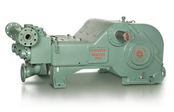
The 2,200-hp mud pump for offshore applications is a single-acting reciprocating triplex mud pump designed for high fluid flow rates, even at low operating speeds, and with a long stroke design. These features reduce the number of load reversals in critical components and increase the life of fluid end parts.
The pump’s critical components are strategically placed to make maintenance and inspection far easier and safer. The two-piece, quick-release piston rod lets you remove the piston without disturbing the liner, minimizing downtime when you’re replacing fluid parts.

A comprehensive range of mud pumping, mixing, and processing equipment is designed to streamline many essential but time-consuming operational and maintenance procedures, improve operator safety and productivity, and reduce costly system downtime.

I’ve run into several instances of insufficient suction stabilization on rigs where a “standpipe” is installed off the suction manifold. The thought behind this design was to create a gas-over-fluid column for the reciprocating pump and eliminate cavitation.
When the standpipe is installed on the suction manifold’s deadhead side, there’s little opportunity to get fluid into all the cylinders to prevent cavitation. Also, the reciprocating pump and charge pump are not isolated.
The gas over fluid internal systems has limitations too. The standpipe loses compression due to gas being consumed by the drilling fluid. In the absence of gas, the standpipe becomes virtually defunct because gravity (14.7 psi) is the only force driving the cylinders’ fluid. Also, gas is rarely replenished or charged in the standpipe.
The suction stabilizer’s compressible feature is designed to absorb the negative energies and promote smooth fluid flow. As a result, pump isolation is achieved between the charge pump and the reciprocating pump.
The isolation eliminates pump chatter, and because the reciprocating pump’s negative energies never reach the charge pump, the pump’s expendable life is extended.
Investing in suction stabilizers will ensure your pumps operate consistently and efficiently. They can also prevent most challenges related to pressure surges or pulsations in the most difficult piping environments.
Sigma Drilling Technologies’ Charge Free Suction Stabilizer is recommended for installation. If rigs have gas-charged cartridges installed in the suction stabilizers on the rig, another suggested upgrade is the Charge Free Conversion Kits.

A well-placed suction stabilizer can also prevent pump chatter. Pump chatter occurs when energy is exchanged between the quick opening and closing of the reciprocating pump’s valves and the hammer effect from the centrifugal pump. Pump isolation with suction stabilizers is achieved when the charge pumps are isolated from reciprocating pumps and vice versa. The results are a smooth flow of pumped media devoid of agitating energies present in the pumped fluid.

Drilling mud is most commonly used in the process of drilling boreholes for a variety of reasons such as oil and gas extraction as well as core sampling. The mud plays an important role in the drilling process by serving numerous functions. The main function it is utilized for is as a lubricating agent. A large amount of friction is generated as drilling occurs which has the potential to damage the drill or the formation being drilled. The mud aids in the decrease in friction as well as lowering the heat of the drilling. It also acts a carrier for the drilled material so it becomes suspended in the mud and carried to the surface.
Using a Moyno progressive cavity pump, the drilling mud with suspended material can be pumped through a process to remove the solids and reuse the cleaned mud for further drilling.

There are many different ways to drill a domestic water well. One is what we call the “mud rotary” method. Whether or not this is the desired and/or best method for drilling your well is something more fully explained in this brief summary.
One advantage of drilling with compressed air is that it can tell you when you have encountered groundwater and gives you an indication how much water the borehole is producing. When drilling with water using the mud rotary method, the driller must rely on his interpretation of the borehole cuttings and any changes he can observe in the recirculating fluid. Mud rotary drillers can also use borehole geophysical tools to interpret which zones might be productive enough for your water well.
The mud rotary well drilling method is considered a closed-loop system. That is, the mud is cleaned of its cuttings and then is recirculated back down the borehole. Referring to this drilling method as “mud” is a misnomer, but it is one that has stuck with the industry for many years and most people understand what the term actually means.
The water is carefully mixed with a product that should not be called mud because it is a highly refined and formulated clay product—bentonite. It is added, mixed, and carefully monitored throughout the well drilling process.
The purpose of using a bentonite additive to the water is to form a thin film on the walls of the borehole to seal it and prevent water losses while drilling. This film also helps support the borehole wall from sluffing or caving in because of the hydraulic pressure of the bentonite mixture pressing against it. The objective of the fluid mixture is to carry cuttings from the bottom of the borehole up to the surface, where they drop out or are filtered out of the fluid, so it can be pumped back down the borehole again.
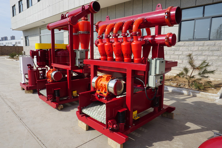
When using the mud rotary method, the driller must have a sump, a tank, or a small pond to hold a few thousand gallons of recirculating fluid. If they can’t dig sumps or small ponds, they must have a mud processing piece of equipment that mechanically screens and removes the sands and gravels from the mixture. This device is called a “shale shaker.”
The driller does not want to pump fine sand through the pump and back down the borehole. To avoid that, the shale shaker uses vibrating screens of various sizes and desanding cones to drop the sand out of the fluid as it flows through the shaker—so that the fluid can be used again.
Before the well casing and screens are lowered into the borehole, the recirculating fluid is slowly thinned out by adding fresh water as the fluid no longer needs to support sand and gravel. The driller will typically circulate the drilling from the bottom up the borehole while adding clear water to thin down the viscosity or thickness of the fluid. Once the fluid is sufficiently thinned, the casing and screens are installed and the annular space is gravel packed.
Gravel pack installed between the borehole walls and the outside of the well casing acts like a filter to keep sand out and maintain the borehole walls over time. During gravel packing of the well, the thin layer of bentonite clay that kept the borehole wall from leaking drilling fluid water out of the recirculating system now keeps the formation water from entering the well.
Some drillers use compressed air to blow off the well, starting at the first screened interval and slowly working their way to the bottom—blowing off all the water standing above the drill pipe and allowing it to recover, and repeating this until the water blown from the well is free of sand and relatively clean. If after repeated cycles of airlift pumping and recovery the driller cannot find any sand in the water, it is time to install a well development pump.
Additional development of the well can be done with a development pump that may be of a higher capacity than what the final installation pump will be. Just as with cycles of airlift pumping of the well, the development pump will be cycled at different flow rates until the maximum capacity of the well can be determined. If the development pump can be operated briefly at a flow rate 50% greater than the permanent pump, the well should not pump sand.
Mud rotary well drillers for decades have found ways to make this particular system work to drill and construct domestic water wells. In some areas, it’s the ideal method to use because of the geologic formations there, while other areas of the country favor air rotary methods.
Some drilling rigs are equipped to drill using either method, so the contractor must make the decision as to which method works best in your area, for your well, and at your point in time.
To learn more about the difference between mud rotary drilling and air rotary drilling, click the video below. The video is part of our “NGWA: Industry Connected” YouTube series:
Gary Hix is a Registered Professional Geologist in Arizona, specializing in hydrogeology. He was the 2019 William A. McEllhiney Distinguished Lecturer for The Groundwater Foundation. He is a former licensed water well drilling contractor and remains actively involved in the National Ground Water Association and Arizona Water Well Association.

Cavitation is an undesirable condition that reduces pump efficiency and leads to excessive wear and damage to pump components. Factors that can contribute to cavitation, such as fluid velocity and pressure, can sometimes be attributed to an inadequate mud system design and/or the diminishing performance of the mud pump’s feed system.
When a mud pump has entered full cavitation, rig crews and field service technicians will see the equipment shaking and hear the pump “knocking,” which typically sounds like marbles and stones being thrown around inside the equipment. However, the process of cavitation starts long before audible signs reveal themselves – hence the name “the silent killer.”
Mild cavitation begins to occur when the mud pump is starved for fluid. While the pump itself may not be making noise, damage is still being done to the internal components of the fluid end. In the early stages, cavitation can damage a pump’s module, piston and valve assembly.
The imperceptible but intense shock waves generated by cavitation travel directly from the fluid end to the pump’s power end, causing premature vibrational damage to the crosshead slides. The vibrations are then passed onto the shaft, bull gear and into the main bearings.
If not corrected, the vibrations caused by cavitation will work their way directly to critical power end components, which will result in the premature failure of the mud pump. A busted mud pump means expensive downtime and repair costs.
To stop cavitation before it starts, install and tune high-speed pressure sensors on the mud suction line set to sound an alarm if the pressure falls below 30 psi.
Although the pump may not be knocking loudly when cavitation first presents, regular inspections by a properly trained field technician may be able to detect moderate vibrations and slight knocking sounds.
Gardner Denver offers Pump University, a mobile classroom that travels to facilities and/or drilling rigs and trains rig crews on best practices for pumping equipment maintenance.
Severe cavitation will drastically decrease module life and will eventually lead to catastrophic pump failure. Along with downtime and repair costs, the failure of the drilling pump can also cause damage to the suction and discharge piping.
When a mud pump has entered full cavitation, rig crews and field service technicians will see the equipment shaking and hear the pump ‘knocking’… However, the process of cavitation starts long before audible signs reveal themselves – hence the name ‘the silent killer.’In 2017, a leading North American drilling contractor was encountering chronic mud system issues on multiple rigs. The contractor engaged in more than 25 premature module washes in one year and suffered a major power-end failure.
Gardner Denver’s engineering team spent time on the contractor’s rigs, observing the pumps during operation and surveying the mud system’s design and configuration.
The engineering team discovered that the suction systems were undersized, feed lines were too small and there was no dampening on the suction side of the pump.
Following the implementation of these recommendations, the contractor saw significant performance improvements from the drilling pumps. Consumables life was extended significantly, and module washes were reduced by nearly 85%.
Although pump age does not affect its susceptibility to cavitation, the age of the rig can. An older rig’s mud systems may not be equipped for the way pumps are run today – at maximum horsepower.
It may be impractical to flush system piping during drilling operations. However, strainer screens should be checked daily to remove any debris or other flow restrictions.

The invention relates generally to the field of measurement while drilling systems. More specifically, the invention relates to methods for reducing the effects of noise caused by “mud” pumps on the signal channel for measurement while drilling systems that use mud flow modulation telemetry or an electromagnetic telemetry.
Measurement while drilling (“MWD”) systems and methods generally include sensors disposed in or on components that are configured to be coupled into a “drill string.” A drill string is a pipe or conduit that is used to rotate a drill bit for drilling through subsurface rock formations to create a wellbore therethrough. A typical drill string is assembled by threadedly coupling end to end a plurality of individual segments (“joints”) of drill pipe. The drill string is suspended at the Earth"s surface by a hoisting unit known as a “drilling rig.” The rig typically includes equipment that can rotate the drill string, or the drill string may include therein a motor that is operated by the flow of drilling fluid (“drilling mud”) through an interior passage in the drill string. During drilling a wellbore, some of the axial load of the drill string to the drill bit located at the bottom of the drill string. The equipment to rotate the drill string is operated and the combined action of axial force and rotation causes the drill bit to drill through the subsurface rock formations.
The drilling fluid (hereinafter “mud”) is pumped through the interior of the drill string by various types of pumps disposed on or proximate the drilling rig. The mud exits the drill string through nozzles or courses on the bit, and performs several functions in the process. One is to cool and lubricate the drill bit. Another is to provide hydrostatic pressure to prevent fluid disposed in the pore spaces of porous rock formations from entering the wellbore, and to maintain the mechanical integrity of the wellbore. The mud also lifts the drill cuttings created by the bit to the surface for treatment and disposal.
In addition to the above mentioned sensors, the typical MWD system includes a data processor for converting signals from the sensors into a telemetry format for transmission of selected ones of the signals to the surface. In the present context, it is known in the art to distinguish the types of sensors used in a drill string between those used to make measurements related to the geodetic trajectory of the wellbore and certain drilling mechanical parameters as “measurement while drilling” sensors, while other sensors, used to make measurements of one or more petrophysical parameters of the rock formations surrounding the wellbore are frequently referred to as “logging while drilling” (“LWD”) sensors. For purposes of the description of the present invention, the term MWD or “measurement while drilling” is intended to include both of the foregoing general classifications of sensors and systems including the foregoing, and it is expressly within the scope of the present invention to communicate any measurement whatsoever from a component in drill string to the surface using the method to be described and claimed herein below.
Communicating measurements made by one or more sensors in the MWD system is typically performed by the above mentioned data processor converting selected signals into a telemetry format that is applied to a valve or valve assembly disposed within a drill string component such that operation of the valve modulates the flow of drilling mud through the drill string. Modulation of the flow of drilling mud creates pressure variations in the drilling mud that are detectable at the Earth"s surface using a pressure sensor (transducer) arranged to measure pressure of the drilling mud as it is pumped into the drill string. Forms of mud flow modulation known in the art include “negative pulse” in which operation of the valve momentarily bypasses mud flow from the interior of the drill string to the annular space between the wellbore and the drill string; “positive pulse” in which operation of the valve momentarily reduces the cross-sectional area of the valve so as to increase the mud pressure, and “mud siren”, in which a rotary valve creates standing pressure waves in the drilling mud that may be converted to digital bits by appropriate phasing of the standing waves.
Irrespective of the type of mud flow modulation telemetry used, detection of the telemetry signal at the Earth"s surface may be difficult because of two principal reasons. First, while drilling mud as a liquid is relatively incompressible, it does have non-zero compressibility. Consequently, as the pressure variation travels from the valve to the surface, some of the energy therein is dissipated by compression and rarefaction of the mud as the wave traverses the drill string. Second, and more importantly, the pumps used to move the drilling mud through the drill string are very large and powerful, and frequently are of the positive displacement type. As a result, the mud pumps themselves generate large pressure variations in the mud as it is pumped through the drill string, thus masking the pressure variation signal being transmitted by the MWD instrument.
U.S. Pat. No. 6,741,185 issued to Pengyu et al. describes a method exploiting the raw pressure to estimate the parameters of the noise. The estimation is carried out in two separated tasks: the estimation of the instantaneous frequency on one side, and the estimation of other parameters on the other side via an adaptive filtering approach. U.S. Patent Application Publication No. 200710192031 submitted by Jiang Li et al. describes a similar approach using a LMS algorithm to estimate the parameters of the noise. Because both estimators are completely separated, the ability of the foregoing methods to cancel mud pump noise over a broad frequency band is limited. U.S. Pat. No. 4,642,800 issued to Umeda et al. describes a mud pump noise canceling method based on the use of a set of “stroke counters” (devices which count the operating cycles of each cylinder of the pump) to estimate the instantaneous frequency of the mud pumps. However, the estimation of the instantaneous frequency is assumed to vary linearly with the stroke counter output which is not necessarily a valid assumption.
The electromagnetic telemetry signal may likewise be masked by signal noise arising from mud pump operation. The mud pumps may create either cyclical electrical interference that mimics the repetitive activity of the mud pumps, or asynchronous noise arising from, for example, electrical interference generated by power drains caused by any sort of mechanical problem.
What is needed is more reliable methods for estimating and reducing mud pump noise for use with mud pulse telemetry and electromagnetic telemetry MWD systems.
A method according to one aspect of the invention for attenuating pump noise in a wellbore drilling system includes spectrally analyzing measurements of a parameter related to operation of a pump used to move drilling fluid through the drilling system. Synthetic spectra of the parameter are generated based on a number of pumps in the pump system and a selected number of harmonic frequencies for each pump. Which of the synthetic spectra most closely matches the spectrally analyzed parameter output is determined. The most closely matching synthetic spectrum is used to reduce noise in a signal detected proximate the Earth"s surface transmitted from a part of the drilling system disposed in a wellbore.
FIG. 1 shows an example drilling system that may use a pump noise reduction method according to the invention. FIG. 1A shows an alternative example drilling system to that illustrated in FIG. 1.
A typical wellbore drilling system, including measurement while drilling (“MWD”) devices that can be used in according with various examples of the invention is shown schematically in FIG. 1. A hoisting unit called a “drilling rig” suspends a conduit of pipe called a drill string 12 in a wellbore 18 being drilled through subsurface rock formations, shown generally at 11. The drill string 12 is shown as being assembled by threaded coupling end to end of segments or “joints” 14 of drill pipe, but it is within the scope of the present invention to use continuous pipe such as “coiled tubing” to operate a drilling system in accordance with the present invention. The rig 10 may include a device called a “top drive” 24 that can rotate the drill string 12, while the elevation of the top drive 24 may be controlled by various winches, lines and sheaves (not identified separately) on the rig 10. A drill bit 16 is typically disposed at the bottom end of the drill string 12 to drill through the formations 11, thus extending the wellbore 18.
As explained in the Background section herein, drilling fluid (“drilling mud”) is pumped through the drill string 12 to perform various functions as explained above. In the present example, a tank or pit 30 may store a volume of drilling mud 32. The intake 34 of a mud pump system 36 is disposed in the tank 30 so as to withdraw mud 32 therefrom for discharge by the pump system 36 into a standpipe, coupled to a hose 26, and to certain internal components in the top drive 26 for eventual movement through the interior of the drill string 12.
The example pump system 36 shown in FIG. 1 is typical and is referred to as a “triplex” pump. The system 36 includes three cylinders 37 each of which includes therein a piston 41. Movement of the pistons 41 within the respective cylinders 37 may be effected by a motor 39 such as an electric motor. A cylinder head 40 may be coupled to the top of the cylinders 37 and may include reed valves (not shown separately) or the like to permit entry of mud into each cylinder from the intake 34 as the piston 37 moves downward, and discharge of the mud toward the standpipe as the piston 37 moves upward. Because the piston velocity is variable even at constant motor speed, the pressure in the standpipe 28 varies as the velocity of the pistons 37 changes. Typical triples pumps such as the one shown in FIG. 1 may include one or more pressure dampeners 43 coupled to the output of the pump system 36 or to the output of each cylinder to reduce the variation in pressure resulting from piston motion as explained above. In some examples, a device to count the number of movements of each piston through the respective cylinder may be coupled in some fashion to the motor or its drive output in order that the system operator can estimate the volume displaced by the pump system 36. One example is shown at 39A and is called a “stroke counter.” Such devices called stroke counters are well known in the art. It should also be noted that the invention is not limited to use with “triplex” pumps. Any number of pump elements may be used in a pump system consistently with the scope of the present invention.
As the drilling mud reaches the bottom of the drill string, it passes through various MWD instruments shown therein such as at 20, 22 and 21. One of the MWD instruments, e.g., the one at 22, may include a mud flow modulator 23 that is coupled to a controller in one of the MWD instruments to modulate the flow of drilling mud to represent signals from one or more of the MWD instruments 20, 22, 21. It should be reemphasized that “MWD” as used in the present context is intended to include “LWD” instrumentation as explained in the Background section herein. Pressure variations representative of the signals to be transmitted to the surface may be detected by one or more pressure transducers 45 coupled into the standpipe side of the drilling mud circulation system. Signals generated by the transducer(s) are communicated, such as over a signal line 44 to a recording unit 46 having therein a general purpose programmable computer 49 (or an application specific computer) to decode and interpret the pressure signals from the transducer(s) 45.
In some examples, electromagnetic telemetry may be used to communicate signals from the MWD instruments 20, 21, 22 to the surface. In such examples, the mud flow modulator may be replaced by an antenna 23A disposed in the drill string and in electrical communication with a telemetry transmitter (not shown separately) in the MWD instrumentation. Low frequency (generally up to about 25 Hz) signals are transmitted through the formations 11 where they may be detected by a surface antenna such as spaced apart electrodes 45A disposed in the ground and in communication with the computer 49 in the recording system 38. In such examples, the pump system 36 may include one or more sensors such as a current meter, Hall effect transducer, or similar device, e.g., at 39B to detect noise generated by the pump system 36.
Having explained the drilling, mud pump system and mud flow modulation telemetry system in general terms, an example mud pump noise reduction technique according to the invention will now be explained with reference to FIG. 2. The following process elements may be performed in the computer in the recording unit, or may be performed in a different computer. At 50, signals from the transducer(s) (45 in FIG. 1), and in electromagnetic telemetry examples from the sensor 39B, may be conducted to a bandpass filter, at 52 to exclude portions of the transducer/sensor signal that are unlikely to be representative of signals transmitted from the MWD instruments. The bandpass filtered signals may be conducted to one input of a summing device 66, which will be further explained below. The filtered pressure/sensor signals may also be conducted to a prediction initializer at 54. As will be further explained, a set of parameters may be initialized at the start of a pump noise signal prediction process. At 56, signals from the stroke counter (39A in FIG. 1) may be used in some examples as part of the parameter initialization. At 58, the stroke counter signals, if used, may be interpolated with respect to time to produce an approximation of certain fundamental frequency mud pump system noise signals.
After initialization, using the bandpass filtered pressure/sensor signals, a set of prediction filters is generated, as shown at 60A, 60B, 60C. For each prediction filter generated, a corresponding correction filter is generated, one such being shown at 62C that corresponds to prediction filter 60C. After generation of the correction filters, a best noise hypothesis is selected at 64. The selected best noise hypothesis is conducted to the summing device 66 to be combined with the bandpass filtered pressure signal from the transducer(s) (45 in FIG. 1). A result, at 68 is “denoised” pressure signals, that is, pressure signals with mud pump system induced noise substantially attenuated. To summarize the noise prediction/correction procedure, the following acts are performed (e.g., in the computer in the recording system). Alternatively an inverse electromagnetic noise signal may be generated and added to the signal detected by the antenna (45A in FIG. 1).
First, a selected time span of pressure data from the transducer (45 in FIG. 1) or sensor signal data (39B in FIG. 1) may be spectrally analyzed. One non-limiting example of spectral analysis is to perform a fast Fourier transform on the selected time span of pressure data. Next is to generate a set of synthetic spectra using the number of mud pumps in the pump system (36 in FIG. 1), and a selected number Mk of harmonic frequencies for the pressure signal generated by each of the pumps. The synthetic spectra may be initialized based on estimated fundamental frequencies from the stroke counter (39A in FIG. 1). Next is to adaptively filter all the foregoing synthetic spectra with a Bayesian filter approach (e.g., Kalman filters) with prediction/correction procedure. Next is to determine which synthetic spectrum most closely matches the measured spectrum (i.e., the sample of pressure data within the selected time span). Next is to synthesize a pump pressure signal from the best match synthetic spectrum. Finally, is to subtract the synthesized pump pressure signal from the pressure transducer signal. Part or all of the foregoing procedure may be repeated in the event the difference between the synthesized pump pressure signal and the measured pressure signal is greater than a selected threshold.
An explanation of the initialization, prediction filter generation, correction filter generation and best hypothesis selection follows. The harmonic structure of the noise generated by the pump system (36 in FIG. 1) can be represented by the mathematical expression:
in which M: is the number of mud pumps in the mud pump system (e.g., three as shown in the example in FIG. 1 but not limited to three); Kmis a selected number of harmonic frequencies associated with the mthpump. Such number of harmonics will depend on the characteristics of the particular pump. am,k(t) is the amplitude of the kthharmonic of the mthpump and θm,kis the initial phase of the kthharmonic of the mthpump.
One purpose of the initialization 54 is to provide an estimate of the instantaneous phase for each mud pump in the pump system. The noise attenuation process is based on automatic detection of spectral peaks with a selected harmonic relationship. The goal is to generate a set of pump output signals that have the highest probabilities to be valid fundamental frequencies of the pump noise. Based on this spectral detection, the method includes selecting a set of P frequencies that are most likely to be the fundamental frequencies of the pressure variations generated by the pump system (36 in FIG. 1).
With a set of P harmonics for M pumps, the number of unique combinations of fundamental frequencies and associated harmonics CpMis determinable by the binomial formula:
Drilling mud, also called drilling fluid, aids in the process of drilling a borehole into the earth. Such holes are drilled for oil and gas extraction, core sampling, and other purposes.
Drilling mud is used to lubricate the drill bit and transport drill cuttings to the surface. Drill cuttings are broken bits of solid material that are produced as the drill bit breaks the rock. As it circulates up from the drill bit, the drilling mud carries drill cuttings up to the surface, where the mud and the cuttings are separated.
Drilling muds have been used to improve drilling operations for much of modern history. Water was used to soften surface material and to remove clippings when groundwater wells were drilled. Contemporary drilling operations are more sophisticated and wells can reach miles below the surface in order to access oil and natural gas deposits.
There are now are three main types of drilling mud: water-based, oil-based, and synthetic-based. The synthetic-based muds are more frequently used because they have less environmental impact and are quicker to biodegrade than water- and oil-based fluids.
Throughout the drilling process, drilling mud is recirculated, which helps decrease waste by reusing as much mud as possible. When the drilling process is finished, the drilling waste must be disposed of in some way. The U.S. Environmental Protection Agency classifies drilling muds as special waste, meaning that they are exempt from many federal regulations. As a result, laws concerning the disposal of drilling muds vary by state.
California, for example, has some strict regulations regarding drilling mud. Pit burial is a very common technique, in which the waste is placed in a manmade or natural excavation. However, burial is not a good method for waste that contains high concentrations of oil and industrial chemicals. The waste can easily contaminate soil and groundwater when the hydrocarbons and other chemicals leach into the earth, and polluted groundwater can take years or even decades to dissipate and often spreads to other areas. Most water-based muds are simply disposed of after the drilling job is completed, but many oil- and synthetic-based muds can be recycled.
Drill cuttings can also be recycled and reused after the hydrocarbons are removed. Recovering drill cuttings and drilling muds is often practical and cost-effective and is an environmentally sustainable process. The most efficient and successful way to remove volatile contaminants from muds and cuttings is thermal desorption. Indirect rotary kilns are ideal for recovering drill cuttings and drilling muds.

Viscosity is critical in determining the selection and sizing of piping, valves, and motors. Using a friction loss chart will detail friction loss data for a given flow rate, pipe size, and fluid viscosity, helping you select the right components for your job. This information combined with available viscosity data will allow a proper analysis of the fluid process system characteristics. Once the fluid process system has been designed and the pump operating parameters defined, the proper pipeline selection can be made. When handling viscous fluids, it can be challenging to determine how they behave. Experience is paramount, as there is no substitute for actually working with these materials out in the field and seeing how they operate.
The EDDY Pump Corporation offers a full line of products that are specifically designed for high viscous fluids. If you are pumping slurry, high solids, extremely viscous material, paste, high abrasives (sand & gravel) and material filled with solids, then you found the best-suited pump for the job. Go to:
The EDDY Pump Corporation offers a full line of products that are specifically designed for high viscous fluids. If you are pumping slurry, high solids, extremely viscous material, paste, high abrasives (sand & gravel), and material filled with solids, then you found the best-suited pump for the job.Go to:https://eddypump.com/products/slurry-pumps/ Or Call Us!


 8613371530291