
drilling rig mud pump knocking sound manufacturer
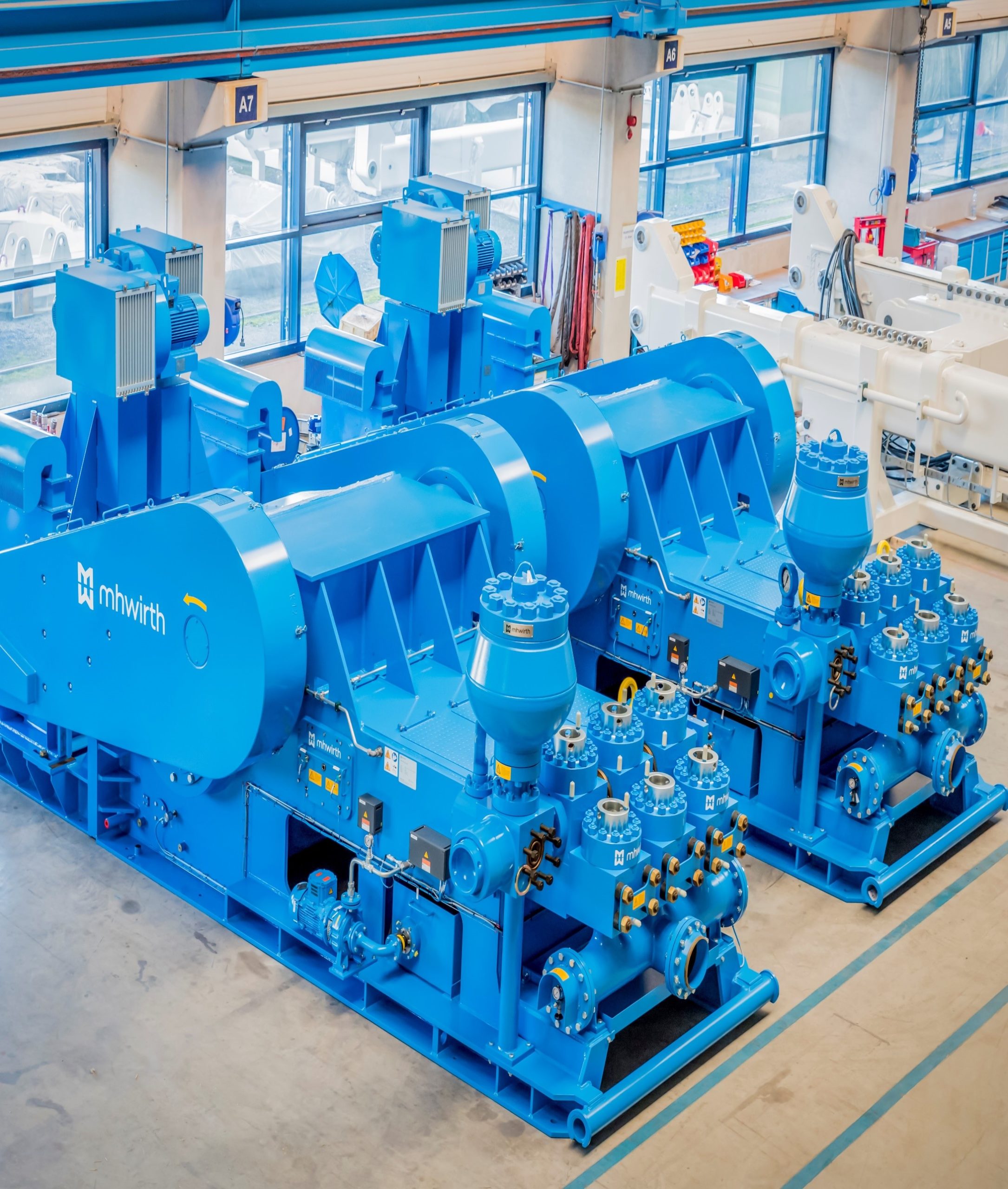
The 2,200-hp mud pump for offshore applications is a single-acting reciprocating triplex mud pump designed for high fluid flow rates, even at low operating speeds, and with a long stroke design. These features reduce the number of load reversals in critical components and increase the life of fluid end parts.
The pump’s critical components are strategically placed to make maintenance and inspection far easier and safer. The two-piece, quick-release piston rod lets you remove the piston without disturbing the liner, minimizing downtime when you’re replacing fluid parts.
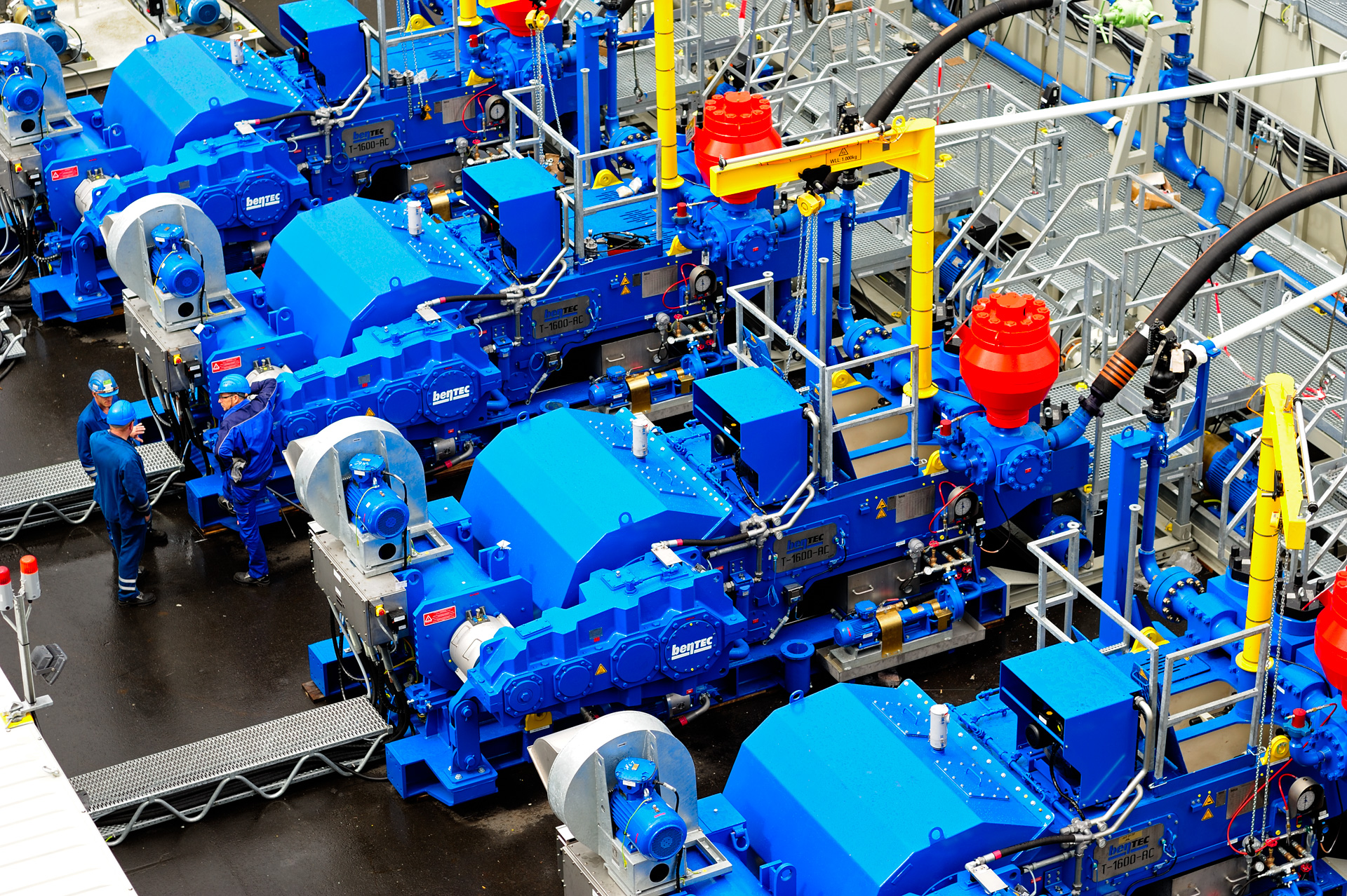
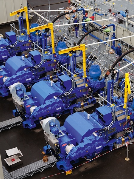
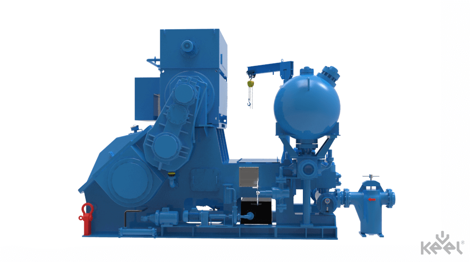
Bentec completely redeveloped the concept of Mud Pumps. Being equipped with a direct-driven gearbox, an own developed motor, and a state-of-the-art pump housing, there is no need for an internal gear coming with many disadvantages and no more belt tensioning.
Bentec Mud Pumps are light weight and have a small footprint. The AC-powered motor is top or rear mounted – suitable for any drilling rig arrangement. The pump is available with 5 000 or 7 500 psi fluid ends, and all its parts that are subject to wear and tear meet API standards and are available worldwide.
A handling crane makes it easy to handle the fluid end components. Furthermore, Bentec uses a patented liner and valve clamping technology to reduce the maintenance time significantly. A quick-change liner and piston system serves for easy maintenance. A special feature of the Bentec MUD PUMP is the side-mounted gear drive.
Liner cooling and gear oiler systems are included; a supercharge pump and a noise reduction package can be installed upon request. The Bentec MUD PUMP is the right choice especially when it comes to noise-sensitive environments such offshore or densely populated environments.
Beyond the supply of Mud Pumps, Bentec acts as system supplier. The pumps can be delivered together with a Bentec Power Control System and a Bentec Soft Pump System.
My first days as an MWD field tech I heard horror stories surrounding what is commonly referred to as “pump noise”. I quickly identified the importance of learning to properly identify this “noise”. From the way it was explained to me, this skill might prevent the company you work from losing a job with an exploration company, satisfy your supervisor or even allow you to become regarded as hero within your organization if you’ve proven yourself handy at this skill.
“Pump noise” is a reference to an instability in surface pressure created by the mud pumps on a modern drilling rig, often conflated with any pressure fluctuation at a similar frequency to pulses generated by a mud pulser, but caused by a source external to the mud pulser. This change in pressure is what stands in the way of the decoder properly understanding what the MWD tool is trying to communicate. For the better part of the first year of learning my role I wrongly assumed that all “noise” would be something audible to the human ear, but this is rarely the case.
In an ideal drilling environment surface pressure will remain steady and all pressure increases, and decreases will be gradual. This way, when the pulser valve closes(pulses), it’s easily detectable on surface by computers. Unfortunately drilling environments are rarely perfect and there are many things that can emulate a pulse thus causing poor or inaccurate data delivery to surface. The unfortunate circumstance of this means drilling operations must come to halt until data can once again be decoded on surface. This pause in the drilling process is commonly referred to at NPT or non-productive time. For those of you unfamiliar these concepts, I’ll explain some of the basics.
A mud pulser is a valve that briefly inhibits flow of drilling fluid traveling through the drill string, creating a sharp rise and fall of pressure seen on surface, also known as a “pulse”.
Depending on if the drilling fluid is being circulated in closed or open loop, it will be drawn from a tank or a plastic lined reservoir by a series(or one) mud pumps and channeled into the stand pipe, which runs up the derrick to the Kelly-hose, through the saver sub and down the drill-pipe(drill-string). Through the filter screen past an agitator or exciter, around the MWD tool, through a mud motor and out of the nozzles in the bit. At this point the fluid begins it’s journey back to the drilling rig through the annulus, past the BOP then out of the flow line and either over the shale shakers and/or back in the fluid reservoir.
Developing a firm grasp on these fundamentals were instrumental in my success as a field technician and an effective troubleshooter. As you can tell, there are a lot of components involved in this conduit which a mud pulser telemeters through. The way in which many of these components interact with the drilling fluid can suddenly change in ways that slightly create sharp changes in pressure, often referred to as “noise”. This “noise” creates difficulty for the decoder by suddenly reducing or increasing pressure in a manner that the decoder interprets a pulse. To isolate these issues, you must first acknowledge potential of their existence. I will give few examples of some of these instances below:
Suction screens on intake hoses will occasionally be too large, fail or become unfastened thus allowing large debris in the mud system. Depending on the size of debris and a little bit of luck it can end up in an area that will inhibit flow, circumstantially resulting in a sudden fluctuation of pressure.
Any solid form of drilling fluid additive, if improperly or inconsistently mixed, can restrict the flow path of the fluid resulting in pressure increase. Most notably this can happen at the pulser valve itself, but it is not the only possible outcome. Several other parts of this system can be affected as well. LCM or loss of circulation material is by far the most common additive, but the least overlooked. It’s important for an MWD technician to be aware of what’s being added into the drilling fluid regardless if LCM isn’t present. Through the years I have seen serval other improperly mixed additives cause a litany of pressure related issues.
This specifically is a term used to refer to the mud motor stator rubber deterioration, tearing into small pieces and passing through the nozzles of the bit. Brief spikes in pressure as chunks of rubber pass through one or more nozzles of the bit can often be wrongly interpreted as pulses.
Sometimes when mud is displaced or a pump suction isn’t completely submerged, tiny air bubbles are introduced into the drilling fluid. Being that air compresses and fluid does not, pulses can be significantly diminished and sometimes non-existent.
As many of you know the downhole mud motor is what enables most drilling rigs to steer a well to a targeted location. The motor generates bit RPM by converting fluid velocity to rotor/bit RPM, otherwise known as hydraulic horsepower. Anything downhole that interacts with the bit will inevitably affect surface pressure. One of the most common is bit weight. As bit weight is increased, so does surface pressure. It’s important to note that consistent weight tends to be helpful to the decoder by increasing the amplitude of pulses, but inconsistent bit weight, depending on frequency of change, can negatively affect decoding. Bit bounce, bit bite and inconsistent weight transfer can all cause pressure oscillation resulting in poor decoding. Improper bit speed or bit type relative to a given formation are other examples of possible culprits as well.
Over time mud pump components wear to the point failure. Pump pistons(swabs), liners, valves and valve seats are all necessary components for generating stable pressure. These are the moving parts on the fluid side of the pump and the most frequent point of failure. Another possible culprit but less common is an inadequately charged pulsation dampener. Deteriorating rubber hoses anywhere in the fluid path, from the mud pump to the saver sub, such as a kelly-hose, can cause an occasional pressure oscillation.
If I could change one thing about today’s directional drilling industry, it would be eliminating the term “pump noise”. The misleading term alone has caused confusion for countless people working on a drilling rig. On the other hand, I’m happy to have learned these lessons the hard way because they seem engrained into my memory. As technology improves, so does the opportunities for MWD technology companies to provide useful solutions. Solutions to aid MWD service providers to properly isolate or overcome the challenges that lead to decoding issues. As an industry we have come a lot further from when I had started, but there is much left to be desired. I’m happy I can use my experiences by contributing to an organization capable of acknowledging and overcoming these obstacles through the development of new technology.

Today"s economy requires that greater attention be given to improve performance of drilling equipment. Understanding the operation of the piston (slush) pump and the associated mud system is vital to improving operations. Improved operation of the piston pump is achieved by providing a mud supply which insures proper filling of the piston pump on each stroke. Testing in a high pressure mud pump research laboratory provided the substantiation of the analytical design approach presented in this paper.Noisy or Normal Pump Operation
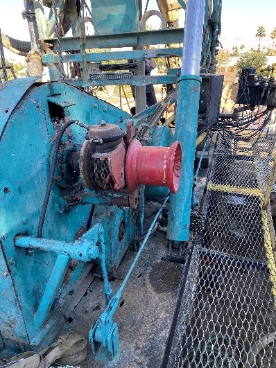
Unusual noise or knocks resulting from various problems. Some are mechanical; parts are loose or broken and must be repaired. One unusual knock is called valve hammer1; which is usually a result of valve and spring design and pump speed. This can also be the result of wear or broken springs. A common noise is hydraulic knock; this is a result of inadequate suction pressure at the operating speed. It results in separation of fluid and piston; this results in water hammer.2 Air intrusion may also cause sound effects where large amounts sometimes cause knocking and small amounts produce a quietening effect. Leaks causing air intrusion should be sealed throughout the piping system and air traps avoided. Air entering through pump packing or pistons on triplex pumps 3 can be eliminated by using new parts or by keeping the cylinder pressure above atmospheric pressure at all times throughout the stroke.Required Suction Pressure Fundamentals
A specific amount of pressure is necessary to force the mud from the tank through the suction piping system into the pump through the valves and against the piston in order to keep the line full of mud. If the line is not full at every point, a void will occur. These voids begin to occur at a particular pump speed. The piston speed varies throughout the stroke. If a void has developed, filling occurs in the last portion of the stroke. When the fluid catches the piston, a collision and knock occur.
The pressure needed to prevent a void is greatest at the start of the stroke. This happens because the piston velocity and the mud in the line to a cylinder is standing still; inertia is high and the mud is difficult to move or accelerate. A large amount of pressure is required to start motion at the rate at which the power end is moving the piston. Pressure is needed to overcome the piping friction and to overcome the inertia of the mud.
American Augers mud pumps are standardstand-alone, self-powered machines thatare the perfect accessories to use with mudmotors, large reamers or whenever moremud volume is needed down hole.* Optional Quiet Pak for optimum noise reduction controlP-600 and P-750 Mud Pumps• allow the operator to get enoughflow to keep the bore flushed cleanof cuttings• are designed with a compact skidmounting and provide a smallfootprint that are ideal for mostdrilling environments.• are compatible with any drill brandmaking them suitable for contractorsoperating a variety of sizes, makesand models of drilling equipment.www.AmericanAugers.com
P-600Mud PumpTypical Flow Rates for Popular Size Mud MotorsBe sure to allow enough extra mud flow to flood the boreMUD MOTOR SIZEFLOW RATE/MINUTEInches Millimeters U.S. Gallons Liters3 3/8 85.72 30 - 120 113.6 - 454.23 1/2 88.9 75 - 160 283.9 - 605.74 3/4 120.6 100 - 250 378.5 - 946.46 3/4 171.4 300 - 600 1,136 - 2,271
What Type of Contractor Should Use aMud Pump?• Users of drilling equipment withpumping capacities of 25 U.S.Gallons (95 L)/minute or largerregardless of soil type or conditions.• Drillers typically making bores thatare greater than 6 1/2 in. (165 mm)diameter and more than 200 ft.(61 m) long.• Owners of mud motors for rockdrilling applications.• Operators in areas where muddisposal is expensive or restricted.Both the P-600 and the P-750should be considered when workingin rock formations where the operatingdrill"s on-board mud pump has fluidlimitedcapacities and cannot produceenough pressure to drive the mud motor.www.AmericanAugers.com
MUD MOTOR SIZEP-750Mud PumpTypical Flow Rates for Popular Size Mud MotorsBe sure to allow enough extra mud flow to flood the boreFLOW RATE/MINUTEInches Millimeters U.S. Gallons Liters3 3/8 85.72 30 - 120 113.6 - 454.23 1/2 88.9 75 - 160 283.9 - 605.74 3/4 120.6 100 - 250 378.5 - 946.46 3/4 171.4 300 - 600 1,136 - 2,2718 203.2 400 - 900 1,514 - 3,407
P-600PERFORMANCE SPECIFICATIONSPower TrainEngine:Caterpillar ® C-15 Tier III Diesel* Tier III or Tier 4i determined by country of purchaseFuel Capacity: 300 U.S. Gallons (1,136 L)Rating:475 HP (354 kW)Transmission: Eaton-FRO-16210B, 10 speedMaximum Speed: 2100 RPMClutch:15 1 /2 in. (394 mm) twin diskNoise Rating: 1 meter distance 104 dB(A)3 meter distance 95 dB(A)Battery:(2) Deka 908DMF 12V, 1450 CCAPumpPump Design:Maximum Pressure:Rated Capacity:Bore x Stroke:Tri-Plex 600GPM1,505 psi (104 bar)600 U.S. Gallons* (2,067 L)/minute6 x 6 in. (152.4 x 152.4 mm)* Note: Pump capacity will vary depending on the overall mud weight,drilling fluid mixture/content and working elevationControlsRemote Controls:Instruments:Mud pump throttle, Mud pump start/stop,clutch actuator, horn remoteDigital mud flow meter (gallons/liters per minute)DimensionsLength: 20 ft. (6.096 m)Height: 9 ft. (2.7 m)Width: 8 ft. (2.49 m)WeightTotal Weight:29,800 lbs. (13,520 kg) estimated39,600 lbs. (17,962 kg) with sound enclosureAccessoriesPulsation dampener on inlet and discharge(2) 25 ft. (7.6 m) suction hoses with 6 in. (152.4 mm)kamlock fittings(2) 25 ft. (7.6 m) discharge hoses with 3 in. (76.2 mm)NPT hammer unionsLiner wash system with supply tank(2) 24 volt work lights* Note: All product performance specifications,components, weights, dimensions and otherrelated information is subject to change withoutnotice from the manufacturer.
P-750PERFORMANCE SPECIFICATIONSPower TrainEngine:Caterpillar ® C-18 Tier III Diesel* Tier III or Tier 4i determined by country of purchaseFuel Capacity: 300 U.S. Gallons (1,136 L)Rating:600 HP (447 kW)Transmission: Eaton-RTLO-22918B, 10 speedMaximum Speed: 2100 RPMClutch:15 1 /2 in. (394 mm) twin diskNoise Rating: 1 meter distance 104 dB(A)3 meter distance 95 dB(A)Battery:(2) Deka 908DMF 12V, 1450 CCAPumpPump Design:Maximum Pressure:Rated Capacity:Bore x Stroke:Quintiplex, piston and liner1,500 psi (103 bar)750 U.S. Gallons* (2,839 L)/minute5 1 /2 x 7 7 /8 in. (139.7 x 200 mm)* Note: Pump capacity will vary depending on the overall mud weight,drilling fluid mixture/content and working elevationControlsRemote Controls:Instruments:Mud pump throttle, Mud pump start/stop,clutch actuator, horn remoteDigital mud flow meter (gallons/liters per minute)DimensionsLength: 25 ft. 6 in. (7.8 m)Height: 10 ft. 3 in. (3.12 m)Width: 8 ft. (2.49 m)WeightTotal Weight:47,800 lbs. (21,680 kg)AccessoriesPulsation dampener on inlet and discharge(2) 25 ft. (7.6 m) suction hoses with 6 in. (152.4 mm)kamlock fittings4 in. (102 mm) NPT hammer union discharge connectionLiner wash system with supply tank(2) 24 volt work lights* Note: All product performance specifications,components, weights, dimensions and otherrelated information is subject to change withoutnotice from the manufacturer.
AMERICAN AUGERSThe American Augers line of underground construction equipment is second-to-none.• Auger Boring Machines• Maxi-Rig & Mid-Size Directional Drills• Oil & Gas Drilling Rigs• Mud Pump & Cleaning Systems• Product Tooling & AccessoriesAmerican Augers products are manufactured at the company’s 241,000 square-foot facility in West Salem, Ohio,in the heart of Amish country between Columbus and Cleveland.Since the founding of American Augers in 1970, there has never been a change in the company’s core value:having products developed by a can-do work force that focuses on mechanical, technological and customer-baseddesign improvements. Our goal is to always exceed customer expectations by providing products that are not acost of doing business, but an Investment in Success.Did You Know? American Augers was the first HDD manufacturer to eliminate chain and utilize a rack andpinion carriage design which is now the industry standard. Our rack and pinion drive provides smoother carriagemovement, more precise operating control, long system life and no complicated parts.American Augers machines are supported through a dedicated parts and technical service department. We are hereto help whenever you need us 24 hours a day, 7 days a week, emergency or not.www.AmericanAugers.comEnvironmental CommitmentAmerican Augers is committed to manufacturing equipment that helps to preserve the sanctity of the globalenvironment, and has done so by reducing noise and/or emissions outputs, and emphasizing the fact that ourtrenchless technology equipment requires little or no open cutting, which has very minimal impacts on naturalsurfaces, features, or habitats.1212

This invention relates to communication systems, and more particularly, to systems and methods for receiving and interpreting data signals being transmitted to the surface of the earth in a logging-while-drilling system. 2. Prior Art
Logging-while-drilling (LWD) or measurement-while-drilling (MWD) involves the transmission to the earth"s surface of downhole measurements taken during drilling. The measurements are generally taken by instruments mounted within drill collars above the drill bit. Indications of the measurements must then be transmitted uphole to the earth"s surface. Various schemes have been proposed for achieving transmission of measurement information to the earth"s surface. For example, one proposed technique transmits logging measurements by means of insulated electrical conductors extending through the drill string. This scheme, however, requires adaptation of drill string pipes including expensive provision for electrical connections at the drill pipe couplings. Another proposed scheme employs an acoustic wave that is generated downhole and travels upward through the metal drill string; but the high levels of interfering noise in a drill string are a problem in this technique.
The most common scheme for transmitting measurement information utilizes the drilling fluid within the borehole as a transmission medium for acoustic waves modulated to represent the measurement information. Typically, drilling fluid or "mud" is circulated downward through the drill string and drill bit and upward through the annulus defined by the portion of the borehole surrounding the drill string. The drilling fluid not only removes drill cuttings and maintains a desired hydrostatic pressure in the borehole, but cools the drill bit. In a species of the technique referred to above, a downhole acoustic transmitter known as a rotary valve or "mud siren", repeatedly interrupts the flow of the drilling fluid, and this causes a varying pressure wave to be generated in the drilling fluid at a frequency that is proportional to the rate of interruption. Logging data is transmitted by modulating the acoustic carrier as a function of the downhole measured data.
One difficulty in transmitting measurement information via the drilling mud is that the signal received is typically of low amplitude relative to the noise generated by the mud pumps which circulate the mud, as the downhole signal is generated remote from the uphole sensors while the mud pumps are close to the uphole sensors. In particular, where the downhole tool generates a pressure wave that is phase modulated to encode binary data, such as is disclosed in U.S. Patent #4,847,815 and assigned to the assignee hereof, and where the periodic noise sources are at frequencies which are at or near the frequency of the carrier wave (e.g. 12 Hz), difficulties arise.
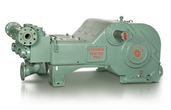
Mud pumps are large positive displacement pumps which generate flow by moving a piston back and forth within a cylinder while simultaneously opening and closing intake and exhaust valves. A mud pump typically has three pistons attached to a common drive shaft. These pistons are one hundred and twenty degrees out of phase with one another to minimize pressure variations. Mud pump noise is caused primarily by pressure variations while forcing mud through the exhaust valve.
The fundamental frequency in Hertz of the noise generated by the mud pumps is equal to the strokes per minute of the mud pump divided by sixty. Due to the physical nature and operation of mud pumps, harmonics are also generated, leading to noise peaks of varying amplitude at all integer values of the fundamental frequency. The highest amplitudes generally occur at integer multiples of the number of pistons per pump times the fundamental frequency, e.g., 3F, 6F, 9F, etc. for a pump with three pistons.
Mud pumps are capable of generating very large noise peaks if pump pressure variations are not dampened. Thus, drilling rigs are typically provided with pulsation dampeners at the output of each pump. Despite the pulsation dampeners, however, the mud pump noise amplitude is typically much greater than the amplitude of the signal being received from the downhole acoustic transmitter. To reduce or eliminate the mud pump noise so that the downhole signal can be recovered, different techniques have been proposed, such as may be found in U.S. Patent Nos. 3,488,629 to Claycomb, 3,555,504 to Fields, 3,716,830 to Garcia, 4,215,425 to Waggener, 4,215,427 to Waggener et al., 4,262,343 to Claycomb, 4,590,593 to Rodney, and 4,642,800 to Umeda. What is common to all of the techniques is that they try to eliminate the mud pump noise by adding the mud pump noise to an inverted version of itself. Most of the techniques utilize two sensors in the mud stream (usually two pressure sensors) and take the difference of signals in an attempt to cancel the mud pump noise without canceling the data signal. Various of the techniques require particular physical arrangements.
The Umeda patent #4,642,800 takes a slightly different approach to eliminating mud pump noise. Umeda teaches that an average pump signature may be found by obtaining the pump signatures in the presence of data over a certain number of pump cycles. The updated average pump signature is corrected by interpolation to match the current pump cycle length and is subtracted from the current pump signature to provide the residual data signal. While the technique disclosed in Umeda may be effective for particular arrangements, it has several drawbacks. First, because Umeda averages pump signatures which include data pulses, unless the effect of the data signal over any averaging period is zero (i.e. non-carrier frequency systems), the data signal which is to be recovered will tend to be undesirably subtracted from itself. Second, because Umeda uses only a single strobe per pump cycle, estimates (e.g. interpolations) are utilized which can introduce significant error. Third, Umeda does not disclose in detail how to treat a multi-pump system. In particular, if Umeda assumes that the pump signature for each pump of a multi-pump system is the same as it would be for a single pump system, large errors are introduced in attempting to cancel out the pump noise, as pumps which are working in multi-pump systems will have different signatures than they would if they were working in a single pump system. In addition, because estimates are required for each pump in the multi-pump system, additional error in the multi-pump system is introduced. SUMMARY OF THE INVENTION
It is therefore an object of the invention to provide methods and systems for accurately recovering data signals introduced into drilling mud in the presence of mud pump noise.
It is another object of the invention to provide methods and systems for accurately recovering logging-while-drilling (LWD) or measurement-while-drilling (MWD) information which is modulated in drilling mud by correlating mud pump piston positions to a mud pressure signature in a calibration procedure.
It is a further object of the invention to provide methods and systems for accurately obtaining LWD or MWD information in multiple mud pump systems by allocating noise attributable to each mud pump and by tracking the mud pump piston position of each mud pump.
Another object of the invention is to provide method and systems for recovering LWD or MWD information transmitted through drilling mud by varying the pressure of the drilling mud regardless of the manner in which the information is coded.
In accord with the objects of the invention, methods for recovering a LWD or MWD data signal in the presence of mud pump noise are provided, and generally comprise calibrating the drilling mud pressure as a function of the mud pump piston position, and then tracking the piston position during transmission of the LWD or MWD data signal and using the calibration information to subtract out the mud pump noise. More particularly, calibration is accomplished in the absence of the LWD or MWD data signal to provide a correlation between mud pump piston position and the drilling mud pressure; i.e., the pressure signature as a function of mud pump piston position is obtained. Then, when the LWD or MWD data signal is being provided, the mud pump piston position is tracked such that the pressure due to the pump can be subtracted; i.e., by knowing the mud pump piston position, the pressure due to the mud pump is found and subtracted from the total received signal to provide the LWD or MWD signal. Where a plurality of mud pumps are used, calibration is accomplished by running the mud pumps together in the absence of the LWD or MWD data signal, and processing the received mud pressure signals in the Fourier domain to allocate respective portions of the mud pressure signals to respective mud pumps such that each mud pump is provided with a signature as a function of its own piston position. With the piston position of each mud pump being tracked, the sum of the mud pressure signals generated by the mud pumps based on their piston positions is subtracted from the total received signal to provide the LWD or MWD signal.
According to a preferred aspect of the invention, the calibration procedure is periodically repeated, e.g., each time additional pipe is added to the drill string, thereby eliminating the effects of depth and mud property variation on the system.
Figs. 8a, 8b, and 8c are respectively the total pump signal, and the signals from pump one and pump two in the multiple pump system calibrated according to Fig. 7.
Figs. 11a and 11b are respectively drilling mud signals prior to and after noise cancellation in a multiple pump system. DETAILED DESCRIPTION OF THE PREFERRED EMBODIMENT
Referring to Fig. 1, the operation of the present invention in a typical drilling arrangement is illustrated schematically. Drilling mud 10 is picked up from mud pit 11 by one or more mud pumps 12 which are typically of the piston reciprocating type. The mud 10 is circulated through mud line 13, down through the drill string 14, through the drill bit 15, and back to the surface of the formation via the annulus 16 between the drill stem and the wall of the well bore 29. Upon reaching the earth"s surface 31, the mud is discharged through line 17 back into the mud pit 11 where cuttings of rock or other well debris are allowed to settle out before the mud is recirculated.
A downhole pressure pulse signaling device 18 is incorporated in the drill string for transmission of data signals derived during the drilling operation by the measurement instrument package 19. Signaling device 18 may be of the valve or variable orifice type which generates pressure pulses in the drilling fluid by varying the speed of flow. A preferred signaling device which generates sinusoidal signals is disclosed in U.S. Patent #4,847,815 assigned to the assignee hereof. Data signals are encoded in a desired form by appropriate electronic means in the downhole tool. Arrows 21, 22, and 23 illustrate the path taken by the pressure pulses provided by the downhole signaling device 18 under typical well conditions. Pump 12 also produces pressure pulses in the mud line 13 and these are indicated by arrows, 24, 25, 26 and 26a which also illustrate the flow of the mud through the annulus 16.
In order for the downhole pressure pulse signals to be recoverable at the surface, some means must be provided to remove or substantially eliminate the portion of the mud pressure signal due to the mud pumps. Subsystem 30, including pressure transducer 32, mud pump piston position sensors 34, and computer or processor 36, comprises such a means.
The preferred pressure transducer 32 of subsystem 30 is a piezoelectric pressure transducer which provides an analog signal which is preferably bandpass filtered by a filter (not shown) or by the computer 36. The preferred mud pump piston position sensor 34 may either comprise an LVDT which utilizes a linear position transducer, or an RVDT which utilizes a rotary position transducer. The LVDT, as shown in Fig. 2a, has an arm 40a, a rod 42a, and a linear position transducer 44a with leads 46a. Arm 40a is coupled to one of the piston rods 47 of the mud pump 12 as well as to rod 42a of the LVDT. Rod 42a moves coaxially within the linear position transducer 44a, which provides a high precision digital indication of the location of piston 48 in the mud pump 12. The RVDT, as shown in Fig. 2b, has an arm 40b, a cable 42b, and an encoder or rotary position transducer 44b with a spring loaded sheave takeup reel 45b. The RVDT also includes leads 46b. Arm 40b of the RVDT of Fig. 2b is coupled to one of the piston rods 47 of the mud pump 12 as well as to the cable 42b of the RBDT. As arm 40b moves with the pump piston rod 47, the cable 42b is let out or reeled onto the takeup reel 45b takeup reel. The rotation of the takeup reel 45b provides a high precision digital indication of the location of piston 48 in the mud pump 12.
Testing has shown that the drilling mud pressure generated by the mud pump 12 is determined by the position of the mud pump piston for a given set of operating conditions. Fig. 3 illustrates how mud pump piston position correlates to mud pump noise. By coupling the linear position transducer 44a or rotary position transducer 44b to the piston rod 47 of the mud pump, a calibration can be performed that measures the pressure generated as a function of piston position.
The preferred calibration procedure for correlating mud pressure generated as a function of piston position for a single mud pump system is seen in Fig. 4. After the pump noise stabilizes in the system, and before the LWD or MWD tool turns on (i.e. before the data signal starts), the signals output by the position sensor 34 and the signals output by the pressure transducer 32 which are bandpass filtered at 39 are preferably recorded at 52 as related position and pressure arrays 55, 57 in the computer (e.g. in computer memory). Preferably, approximately eight seconds of data (e.g., five to ten pump cycles) are accumulated. Then, averages of the pressure as a function of position are calculated (thereby reducing random pressure variations) at 58 to produce a single position vs. pump noise calibration array 59. Indications of the average calibration array or the inverse thereof are stored and used for canceling mud pump noise as is hereinafter described.
The noise cancellation procedure according to the invention is set forth in Fig. 5. Upon the turning on of the downhole tool and the transmission of LWD or MWD data (hereinafter referred to simply as LWD data for sake of brevity), the position sensor 34 and pressure transducer 32 continue to provide indications of piston location and mud pressure; except that the piston position data is used in real time to determine the electrical signal (based on the calibration array 59) which must be subtracted from the composite LWD/noise signal to cancel the noise component of the signal and leave only the LWD signal. Thus, as shown in Fig. 5, the position sensor signal is sampled at 62 (i.e. based on the position sensor signal, the average calibration array is accessed and a corresponding pump noise is provided), and the corresponding pump noise pressure 64 is subtracted at 66 from the real time sensed pressure 32 which was bandpass filtered at 67 to eliminate high frequency components. The difference between the real time sensed pressure and the pump noise pressure provides an indication of the LWD data signal 68.
Test results of a real time sensed pressure pump noise signal are seen in Fig. 6a, where the amplitude of the signal as expressed in dB (in 10dB increments) is plotted versus the frequency expressed in Hz (in 4Hz increments). As seen in Fig. 6a, the noise signal includes several peaks having amplitudes between -10dB and 0dB, and even includes a peak having an amplitude exceeding 10dB. The noise signal of Fig. 6a was then subjected to the noise cancellation procedure of Fig. 5. The noise signal remaining after mud pump noise cancellation is seen in Fig. 6b, and shows that the calibration and noise cancellation procedures reduced noise considerably. In fact, the largest remaining noise peak found at about 5Hz, has an amplitude of approximately -15dB, which is more than 25dB less than the largest peak seen in Fig. 6a prior to noise cancellation.
Turning to Fig. 7, a flow chart of the mud pump calibration procedure for a system utilizing two mud pumps is seen. After the pump noise stabilizes in the system, and before the LWD tool turns on (i.e. before the data signal starts), the signals output by each position sensor 34a, 34b and the signal output by the pressure transducer 32 and filtered at 39 by a bandpass filter which measures composite pump noise are recorded as related position arrays 55a, 55b and pressure array 57 in the computer (e.g. in computer memory). Preferably, approximately twelve seconds of data are accumulated in computer memory at 52; Fig. 8a showing an example of the analog pressure signal which is digitized and stored as part of the array. A fast Fourier transform (FFT) of the composite pump noise signal is then conducted at 70 by the computer. As a result of the FFT, the amplitude and phase of all frequencies contained in the composite mud pump noise signal is obtained at 70 (see Fig. 9a). Utilizing the operating speed of each pump which can be computed from the position sensor of each mud pump, the fundamental frequency and harmonics for each pump are calculated at 72. Then, at 75, the amplitude and phase information for each fundamental and harmonic frequency are extracted from the FFT and assigned to its source (i.e. a particular one of the mud pumps) to provide results as seen in Figs. 9b and 9c. Taking an inverse Fourier transform of the frequency spectra of Figs. 9b and 9c at 76a and 76b, signals attributable to each of the pumps are obtained as seen in Figs. 8b and 8c. As indicated in Fig. 7 at 58a and 58b, the position of each mud pump position sensor is related to the mud pressure generated by the respective mud pump, and an average of the pressure as a function of position is calculated for each mud pump to produce two position vs. pump noise calibration arrays 59a and 59b. Indications of the average calibration arrays are stored in computer memory and used for canceling mud pump noise as is described above with reference to Fig. 10.
Referring now to Fig. 10, the noise cancellation procedure for a system using multiple mud pumps is seen. Upon the turning on of the downhole tool and the transmission of LWD data, the position sensors 34a and 34b and pressure transducer 32 continue to provide indications of piston location and mud pressure; except that the piston position data is used in real time to determine the electrical signal (based on the calibration arrays 59a and 59b) which must be subtracted from the composite LWD/noise signal to cancel the noise component of the signal and leave only the LWD signal. Thus, as shown in Fig. 10, the position sensor signals are sampled at 62a and 62b (i.e. based on the position sensor signals, the average calibration arrays 59a and 59b are accessed and corresponding pump noises are provided), and the corresponding pump noise pressures 64a and 64b are subtracted at 66 from the real time sensed pressure 32 which was bandpass filtered at 67 to eliminate high frequency components. The difference between the real time sensed pressure and the pump noise pressures provides an indication of the LWD data signal 68. That signal is then decoded according to techniques known in the art which are not part of the present invention.
Test results of a real time sensed pressure containing pump noise for two mud pumps is seen in Fig. 11a where amplitude is plotted against frequency. As seen in Fig. 11a, numerous noise peaks having amplitudes of -20dB or higher are seen, with the largest peak of about -5dB at 5Hz. The pressure signal obtained after utilizing the calibration and noise cancellation steps of Figs. 7 and 10 in order to substantially cancel mud pump noise from the signal of Fig. 10a is seen in Fig. 10b. As seen in Fig. 10b, the remaining noise is substantially reduced relative to the noise of Fig. 10a, with the largest peak of about -18dB occurring at approximately 18Hz.
There have been described and illustrated herein methods and apparatus for canceling mud pump noise in order to recover a logging while drilling signal. While particular embodiments of the invention have been described it is not intended that the invention be limited exactly thereto, as it is intended that the invention be as broad in scope as the art will allow. Thus, while particular pressure transducers, position sensors, pump-types, computers, FFT programs, and the like have been disclosed, it will be appreciated that other equipment and programs can be utilized effectively. Similarly, while certain preferred data gathering time periods were disclosed prior to running the LWD or MWD tool, it will be appreciated that other time frames could be utilized. Also, while the invention was described with reference to LWD and MWD procedures, it will be appreciated that the terms LWD and MWD are intended to include any other data signaling procedure where data is transmitted in drilling mud in the presence of mud pump noise. Further, while the invention was disclosed with reference to systems utilizing one or two mud pumps, it will be appreciated that the teachings equally apply to systems utilizing additional mud pumps. All that is required is that the pressure signature of each mud pump relative to its piston position be obtained via transforming the total signal into the Fourier domain, dividing the Fourier response among the various mud pumps based on their fundamental and harmonic frequencies, and converting the responses back into respective pressure signatures. It will be understood, of course, that where two mud pumps are working in unison (i.e. at the same frequency), their signatures can be treated together. Therefore, it will be apparent to those skilled in the art that other changes and modifications may be made to the invention as described in the specification without departing from the spirit and scope of the invention as so claimed.

Drilling consumables such as mud pump systems and their components can drastically increase your uptime while reducing costs and health/safety/environmental (HSE) risks. To support your drilling needs, Forum’s patented P-Quip® mud pump system offers a single-source solution that integrates high-quality fluid end components for maximum longevity and performance.
With more than 20 years of successful operation in severe environments, P-Quip offers a proven track record for the lowest cost of ownership in the industry. As part of our commitment to quality, our mud pump parts use patented Banded Bore™ technology that significantly reduces stress concentrations and leads to longer module life.
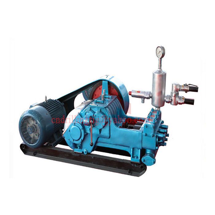
And the Chinese New Year is coming, if you need mud pumps or spare parts, please kindly prepare it in advance. Especially for Indian wholesalers, BW-600 and BW-800 mud pump"s spare parts will be a good choice for you,many of our end customers need them.

The pump is designed to circulate mud or drilling fluid under great pressure down the drill hole and back up. The pump is a reciprocating model that features five pistons, hence the name quintuplex mud pump. The right degree of pressure and precision is crucial for efficient well operations. At Shale Pumps, we understand the value of a well designed and manufactured quintuplex pump, lending great focus on robust build and superior engineering quality.
Despite the fact that all mud pumps have pulsation dampeners, noise levels are likely to be high and require modifications to keep noise pollution levels low. This is important, considering the long-running hours of equipment and the need to protect personnel from constant and high noise levels. With a quintuplex mud pump, the pulsation noise and the mud telemetry noise come down by as much as half, making operations less noisy.
At Shale Pumps the designs of quintuplex mud pumps incorporate smaller footprints making the pumps more compact. Despite the smaller size of the pumps, the quintuplex pumps are rated for continuous duty with greater efficiency. The pressurized lubrication system with lubrication pumps mounted on the outside makes it easy for maintenance, reducing downtime of the equipment.
The build quality of the quintuplex mud pumps, much like the other equipment we manufacture and assemble at Shale pumps are superior, as a result of the materials, the design, and the processes employed in the assembly line. For detailed information about the service call at 713.248.3999 or mail at sales@shalepumps.com.
Mud pumps for drilling rigs are used in most of the off-shore projects, and it is one of the essential equipment used in these types of projects. The plus point of using the mud pump is that the operation has been appropriately checked and proven in th …
Drilling mud pumps are used on rigs for mud circulation. The pumps suit the best for processing drilling oil wells. Shale Pumps offer different types of used, remanufactured, and new drilling equipment for international and domestic drilling companies. …
When you are using the good frac pump, the success of the oil and gas drilling operations is ensured. The latest equipment that is used is the quintuplex pump. This pump comes with five plungers responsible for pushing the drilling fluid into a drill s …
For the extraction of water, oil, and gas, horizontal directional drilling equipment is used. This equipment is an underground infrastructure. This technique is directed through a curvature or conducted from the surface level as well. This process invo …
Horizontal Directional Drilling Equipment (HDD) is used for installing utilities located underground. We at Shale Pumps use HDD equipment like cables and pipes. 5,000 to 100,000 lbs range of models are available with us. If you want to get well-communi …
Mud pumps are used for drilling operations and they are reciprocating plunging pumps. It works by circulating the drilling fluid or the mud on the drilling rig. Drilling mud pumps are the most important types of equipment used in the oil drilling proce …
The horizontal directional drilling (HDD) technology and pump are used for water, oil, and gas piping, in underground infrastructure. The HDD technique can be directed through a curvature or conducted from the surface level as well. The Horizontal Dire …
The drilling mud pumps are of immense utility to the oil companies, for the purposes related to oil well drilling. The pumps have the reciprocating piston for circulating the drilling fluid. These units work at high pressure and provide for low noise, …
Horizontal directional drilling HDD is one typical method needed for the installation of underground pipelines, service conduit, and cables via trenchless methods. It makes use of horizontal directional drilling machine and other related attachments fo …
Before you directly go to the topic of Drilling Mud Pump Companies in Houston, it is important for us to know about this specific pump. So what exactly is this pump and its role? Well, a mud pump is the one which is basically a reciprocating piston pu …

Mud pumps are akin to the heart, they are key equipment in oil and gas drilling that pumps and circulates the drilling mud. As a key player in the manufacture and sales of oilfield equipment, we have a complete range of triplex mud pumps with compact design, reduced carbon emission, and improved performance.
Our classes of onshore and offshore mud pumps range from 450 to 2,200 hp diesel or electric (AC or DC) powered with 3000 to 5000 psi ratings. We design our mud pumps to match different rig types, work optimally and safely both onshore and offshore.
When choosing a size and type of mud pump for your drilling project, there are several factors to consider. These would include not only cost and size of pump that best fits your drilling rig, but also the diameter, depth and hole conditions you are drilling through. I know that this sounds like a lot to consider, but if you are set up the right way before the job starts, you will thank me later.
Recommended practice is to maintain a minimum of 100 to 150 feet per minute of uphole velocity for drill cuttings. Larger diameter wells for irrigation, agriculture or municipalities may violate this rule, because it may not be economically feasible to pump this much mud for the job. Uphole velocity is determined by the flow rate of the mud system, diameter of the borehole and the diameter of the drill pipe. There are many tools, including handbooks, rule of thumb, slide rule calculators and now apps on your handheld device, to calculate velocity. It is always good to remember the time it takes to get the cuttings off the bottom of the well. If you are drilling at 200 feet, then a 100-foot-per-minute velocity means that it would take two minutes to get the cuttings out of the hole. This is always a good reminder of what you are drilling through and how long ago it was that you drilled it. Ground conditions and rock formations are ever changing as you go deeper. Wouldn’t it be nice if they all remained the same?
Centrifugal-style mud pumps are very popular in our industry due to their size and weight, as well as flow rate capacity for an affordable price. There are many models and brands out there, and most of them are very good value. How does a centrifugal mud pump work? The rotation of the impeller accelerates the fluid into the volute or diffuser chamber. The added energy from the acceleration increases the velocity and pressure of the fluid. These pumps are known to be very inefficient. This means that it takes more energy to increase the flow and pressure of the fluid when compared to a piston-style pump. However, you have a significant advantage in flow rates from a centrifugal pump versus a piston pump. If you are drilling deeper wells with heavier cuttings, you will be forced at some point to use a piston-style mud pump. They have much higher efficiencies in transferring the input energy into flow and pressure, therefore resulting in much higher pressure capabilities.
Piston-style mud pumps utilize a piston or plunger that travels back and forth in a chamber known as a cylinder. These pumps are also called “positive displacement” pumps because they literally push the fluid forward. This fluid builds up pressure and forces a spring-loaded valve to open and allow the fluid to escape into the discharge piping of the pump and then down the borehole. Since the expansion process is much smaller (almost insignificant) compared to a centrifugal pump, there is much lower energy loss. Plunger-style pumps can develop upwards of 15,000 psi for well treatments and hydraulic fracturing. Centrifugal pumps, in comparison, usually operate below 300 psi. If you are comparing most drilling pumps, centrifugal pumps operate from 60 to 125 psi and piston pumps operate around 150 to 300 psi. There are many exceptions and special applications for drilling, but these numbers should cover 80 percent of all equipment operating out there.
The restriction of putting a piston-style mud pump onto drilling rigs has always been the physical size and weight to provide adequate flow and pressure to your drilling fluid. Because of this, the industry needed a new solution to this age-old issue.
As the senior design engineer for Ingersoll-Rand’s Deephole Drilling Business Unit, I had the distinct pleasure of working with him and incorporating his Centerline Mud Pump into our drilling rig platforms.
In the late ’90s — and perhaps even earlier — Ingersoll-Rand had tried several times to develop a hydraulic-driven mud pump that would last an acceptable life- and duty-cycle for a well drilling contractor. With all of our resources and design wisdom, we were unable to solve this problem. Not only did Miller provide a solution, thus saving the size and weight of a typical gear-driven mud pump, he also provided a new offering — a mono-cylinder mud pump. This double-acting piston pump provided as much mud flow and pressure as a standard 5 X 6 duplex pump with incredible size and weight savings.
The true innovation was providing the well driller a solution for their mud pump requirements that was the right size and weight to integrate into both existing and new drilling rigs. Regardless of drill rig manufacturer and hydraulic system design, Centerline has provided a mud pump integration on hundreds of customer’s drilling rigs. Both mono-cylinder and duplex-cylinder pumps can fit nicely on the deck, across the frame or even be configured for under-deck mounting. This would not be possible with conventional mud pump designs.
Centerline stuck with their original design through all of the typical trials and tribulations that come with a new product integration. Over the course of the first several years, Miller found out that even the best of the highest quality hydraulic cylinders, valves and seals were not truly what they were represented to be. He then set off on an endeavor to bring everything in-house and began manufacturing all of his own components, including hydraulic valves. This gave him complete control over the quality of components that go into the finished product.
The second generation design for the Centerline Mud Pump is expected later this year, and I believe it will be a true game changer for this industry. It also will open up the application to many other industries that require a heavier-duty cycle for a piston pump application.


 8613371530291