
drywall taping mud pump manufacturer

{"links":[{"url":"https://www.graco.com/us/en/contractor/solutions/articles/how-to-mix-drywall-mud-for-texture-spraying.html", "anchor_text":"How to Mix Drywall Mud for Texture Spraying"},{"url":"https://www.graco.com/us/en/contractor/products/drywall-finishing-interior-texture/interior-texture-sprayers.html", "anchor_text":"Interior Texture Sprayers"},{"url":"https://www.graco.com/us/en/contractor/products/drywall-finishing-interior-texture/drywall-finishing-tools-accessories.html", "anchor_text":"Drywall Finishing Tools & Accessories"}]}

Drywall Master Taping Tools Extended Quick Clean Mud Pump is used to fill automatic taping tools with mud compound. DrywallMaster pump uses gooseneck (sold separately) to fill automatic taper. Box filler (also sold separately) attaches to pump to fill all other finishing tools. Industry exclusive double o-ring head seal on Drywall Master mud pump keeps mud from seeping between head and pump tube for better seal and easier separating, cleaning or maintenance.
Unique dual o-ring head seal keeps mud from getting between head casting and pump tube. This makes pump easier to separate for cleaning or maintenance.
The Loading Pump, with appropriate accessories (Gooseneck and/or Filler Adapter), is used to fill the following tools: Automatic Taper, Corner Applicator/Corner Box, Nail Spotter, and Flat Box. Attach the Gooseneck to fill the Automatic Taper. Attach the Filler Adapter to fill the Nail Spotter, Corner Applicator, and Flat Box. Simply hang the tube of Loading Pump into a bucket of mud, leaving the leg of the Pump on the floor. Attach the appropriate accessory to the pump. Prime the Pump by pumping the handle a couple of times. Now you should be ready to fill your tool.

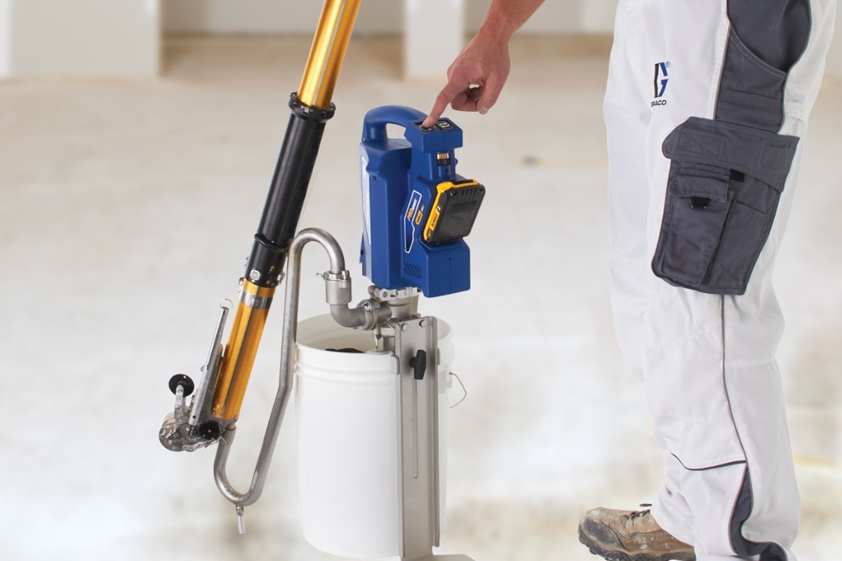
Introducing the industry’s first cordless powered loading pump for drywall mud. Designed to fill all automatic taping and finishing tools. PowerFill totally eliminates the need to manually pump. Now you can quickly fill with just the push of a button.
Never Hand Pump Again. Single-button pumping eliminates fatigue and injury associated with manual pumping. Pumps up to 3.5 gpm for lightning-fast filling and up to 55 gallons on a single battery charge for all-day filling. Programmable to refill tools automatically with Precision Fill.
Automatic Taping Tools are more powerful and efficient than traditional hand tools. Whether you"re a drywall professional, remodeler, or DIY, automatic taping tools achieve better results in half the time. Drywall Loading Pumps (mud pumps) are compound pumps that use Gooseneck and Box Fillers Adaptors to fill drywall taping and finishing tools. All-Wall offers the largest selection of Loading Pumps from top brands such as TapeTech, Columbia, Asgard, Graco, and Drywall Master.

Drywall loading pumps are used to load drywall joint compound into the automatic taping tools. The box filler attachment is used for filling the flat boxes, corner boxes, nail spotters, the MudRunner®, and some compound tubes. The gooseneck attachment is used for filling the automatic drywall taper. Most Drywall loading pumps can be used interchangeably with other manufacturers, with the exceptions of BlueLine and TapeWorm.

© Copyright 2023. Pictures and descriptions are not to be copied or distributed without written consent from Great Lakes Taping Tools™. All Rights Reserved.

Platinum Drywall Tools 3.5 Inch Corner Flusher Platinum Drywall Tools 3.5″ Corner Flusher is the perfect choice for your base coat or finish coat. Made from surgical stainless spring steel that holds its form, this flusher was built to last! … Read More

This Invention relates to tools used to install and finish drywall in buildings and to hand pumps for pumping viscous fluids. BACKGROUND OF THE INVENTION
Drywall, also known as gypsum board, wallboard, and plasterboard, is a building material used to finish the interior surfaces of walls and ceilings in houses and other buildings. Rigid sheets or panels of drywall are formed from gypsum plaster, the semi-hydrous form of calcium sulphate (CaSO4.½× H2O), which is typically sandwiched between two layers of heavy paper or fiberglass mats. Drywall sheets are about ½ inch thick and are nailed or screwed in place to form the interior surfaces of the building, and provide fire resistance and sound deadening, among other benefits.
The joints between drywall sheets are typically filled and sealed with strips of paper or fiberglass mat and drywall joint compound, also called “joint compound”, “drywall mud”, or just “mud”. Joint compound may be made, for example, of water, limestone, expanded perlite, ethylene-vinyl acetate polymer and attapulgite. Joint compound is applied as a viscous fluid that is thick enough to maintain its shape while it hardens. In addition to forming joints, drywall mud is used to cover nail or screw heads, form a smooth or flat surface, and provide a texture over the surface. Paint or wall paper is typically applied over the drywall and joint compound.
Workers often specialize in the installation of drywall, and in large projects different crews install the drywall panels (drywall hangers) from those who finish the joints and apply the joint compound (tapers or mudmen). Workers who specialize in drywall installation often use specialized tools to increase their productivity including flat boxes that are tools used to hold joint compound and apply it to drywall joints. Joint compound is often mixed (e.g., with water) or stored in buckets, and drywall mud pumps have been used to pump the mud from the buckets into flat boxes or other tools or containers.
U.S. patent application Ser. No. 11/292,238, publication 2007/0122301 (also by Werner Schlecht) describes a drywall mud pump. However, it was found that in operation pumping drywall joint compound that friction developed within the pump making it difficult to use. Thus, needs or potential for benefit exist for drywall mud pumps that have less internal friction. In addition, needs and potential for benefit exist for drywall mud pumps that are inexpensive to manufacture, reliable, easy to use, that have a long life, that are easy to service and clean, and that are simple in operation so that typical operators can effectively maintain them. Room for improvement exists over the prior art in these and other areas that may be apparent to a person of ordinary skill in the art having studied this document. Summary of Particular Embodiments of the Invention
This invention provides, among other things, certain drywall mud (drywall joint compound) pumps with particular features or capabilities. Various embodiments provide, as objects or benefits, for example, that they have less internal friction than certain prior art pumps. In addition, particular embodiments provide, for instance, as objects or benefits, drywall mud pumps that are inexpensive to manufacture, reliable, easy to use, that have a long life, that are easy to service and clean, that are simple in operation, or a combination thereof. Other benefits of certain embodiments may be apparent to a person of ordinary skill in the art.
In specific embodiments, this invention provides certain drywall mud pumps that include a main cylinder and a rod having two ends, a first end and a second end. In many embodiments, when the drywall mud pump is assembled, the second end of the rod is located within the main cylinder, for example. Various embodiments also include a piston which, when the drywall mud pump is assembled, is also located within the main cylinder and is attached to the second end of the rod. In some embodiments, there is a connection structure between the piston and the second end of the rod, which is configured to allow the second end of the rod to move relative to the piston in a direction that is substantially perpendicular to the axis of the rod. A number of embodiments include a means for allowing the second end of the rod to move laterally relative to the piston within the main cylinder. Further, in some embodiments the piston specifically includes an elongated hole that receives the second end of the rod, and the elongated hole allows the second end of the rod to move laterally relative to the piston.
Various such embodiments further include a pump head, which may have an output aperture, and when the drywall mud pump is assembled, the pump head may be connected to the main cylinder and the rod may pass through the pump head. In some embodiments, the drywall mud pump further includes a handle and a linkage, and when the drywall mud pump is assembled, the handle may be pivotably connected to the first end of the rod, and the linkage may be pivotably connected to the pump head and pivotably connected to the handle, as examples. Moreover, some embodiments may include (e.g., in the pump head) a means for guiding the rod, a means for allowing the rod to pivot as the second end of the rod moves laterally relative to the piston, or both. Further, particular embodiments include a guide having a hole through which the rod slidably passes. Some embodiments include just one guide in the pump head, which may serve as both a guide and as a pivot point for the rod, and in some embodiments, the guide may be shortened to provide for pivoting.
In a number of embodiments, the piston includes an elastomeric piston cup having a first hole, which may be elongated, a top rigid support having a second elongated hole, a bottom rigid support having a third elongated hole, and a flapper having a fourth elongated hole. In some embodiments, when the drywall mud pump is assembled, the second end of the rod passes through each of the first, second, third, and fourth holes, for example. Further, certain embodiments include a means for preventing the piston from rotating about the rod. In some embodiments, as an example, the second end of the rod has a flattened portion, at least the second and third elongated holes are substantially the same size and have substantially the same shape, and, when the drywall mud pump is assembled, are held in a particular orientation by the flattened portion of the second end of the rod.
Even further, in some embodiments, when the drywall mud pump is assembled, the second end of the rod is attached to the piston with a nut (e.g., a lock nut), an elongated washer, or both. Moreover, in some embodiments, the piston cup, the top rigid support, and the bottom rigid support each have at least one passageway therethrough for passage of the drywall mud, and when the drywall mud pump is assembled, the flapper covers the (at least one) passageway substantially blocking passage of the drywall mud when the piston is moving in the main cylinder toward the pump head.
In various embodiments, the piston cup, the top rigid support, and the bottom rigid support each have multiple passageways therethrough for passage of the drywall mud, and the multiple passageways substantially surround the first, second, and third elongated holes. In addition, in some such embodiments, a plurality of the multiple passageways for passage of the drywall mud have at least one curved side and at least one straight side. Additionally, in particular embodiments wherein an elongated washer is provided, when the drywall mud pump is assembled, the washer substantially blocks the elongated hole in the piston to prevent drywall mud from passing through the elongated hole in the piston. In a number of such embodiments, the drywall mud pump may also include a means for controlling the rotational position of the washer.
Further, in some embodiments, the second end of the rod includes a first reduced diameter flattened section and a second reduced diameter flattened section. In some such embodiments, for example, the second reduced diameter flattened section has a smaller diameter, thickness between flats, or both, than the first reduced diameter flattened section. Further, in some embodiments, the second end of the rod also includes a threaded section. Further still, in some embodiments, when the drywall mud pump is assembled, the second end of the rod passes through each of the first, second, third, and fourth elongated holes such that the fourth elongated hole is located at the first reduced diameter flattened section, and the first, second and third elongated holes are located at the second reduced diameter flattened section. In addition, various other embodiments of the invention are also described herein. BRIEF DESCRIPTION OF THE DRAWINGS
FIG. 7 is an isometric exploded view of the piston, rod, and pump head of the example of a mud pump of the previous figures, except that the piston in FIG. 7 is not shown exploded;
FIG. 1 illustrates an example of an assembled drywall mud pump, pump 10. Parts and features that are visible from the outside in this view include output aperture 11 in pump head 14 where drywall mud emerges from pump 10 when handle 12 is moved, for example, by an operator of drywall mud pump 10. In some embodiments, a detachable high filler (not shown) may attach to aperture 11 (e.g., with the nuts 11 nshown) and may extend the location where the mud emerges to a higher elevation to enhance ergonomics. FIG. 2 is an exploded view of the same embodiment of drywall mud pump 10 shown in FIG. 1.
In the embodiment illustrated, rod 13 passes through pump head 14 (visible in FIG. 1 through aperture 11) into main cylinder 15. Pump head 14 is mounted on or connected to main cylinder 15, in this embodiment, with clips 25. Also in this embodiment, handle 12 is pivotably connected to the top or first end 21 of rod 13 with pin 23, and linkage 16 is pivotably connected at the top (of linkage 16) to handle 12 and at the bottom (of handle 16) to pump head 14 with bolts 26.
Other visible parts of pump 10 include foot plate 18, which is connected to pump head 14 with bolts 28, in this embodiment, and foot valve 19, which is connected to the bottom end of cylinder 15 with pin 29.
When in use, main cylinder 15 may extend into a bucket of drywall joint compound or mud while foot plate 18 may extend outside of the bucket to the floor. The operator may place his foot on foot plate 18 to steady pump 10 while moving handle 12. Foot valve 19, in the bottom of the bucket, may form or include a check valve that may allow mud to flow upward into cylinder 15, but may substantially prevent mud from flowing downward out of cylinder 15 through foot valve 19. Rod 13 also passes through shortened guide 17, in this embodiment, and guide 17 is attached to pump head 14 with bolts 27. Thus, guide 17 is easily removable and replaceable.
FIG. 2 also introduces piston 20, which, in this embodiment, includes several different components that will be discussed in more detail with reference to other figures. In this embodiment, when drywall mud pump 10 is assembled, piston 20 is located within main cylinder 15 and is attached to the bottom or second end 22 of rod 13. In addition, when drywall mud pump 10 is assembled, second end 22 of rod 13 is also located within main cylinder 15. When an operator pushes handle 12 down, piston 20 goes up toward pump head 14, pushing drywall mud that is in cylinder 15 out through aperture 11. During this process, a vacuum is created below piston 20, which draws more drywall mud into cylinder 15 through foot valve 19. When the operator pulls handle 12 up, piston 20 goes down, away from pump head 14, foot valve 19 prevents the drywall mud below piston 20 from exiting cylinder 15 through the bottom, and drywall mud flows through piston 20, as will be described in more detail below.
During the operation of mud pump 10, horizontal or lateral forces are exerted on rod 13. Even if the operator only exerts vertical forces on handle 12, since linkage 16 is not vertical during most of the stroke of piston 20, linkage 16 exerts lateral forces on handle 12, which are carried by handle 12 to rod 13. These horizontal or lateral forces on rod 13 are believed to cause increased friction or binding within prior art drywall mud pumps. In a number of embodiments, drywall mud pump 10, and various other drywall mud pumps in accordance with this invention, allow rod 13 to move laterally without binding (or with reduced binding) and in a manner that reduces friction (e.g., within mud pump 10). In different embodiments, such a reduction in friction makes the drywall mud pump (e.g., 10) easier to use. In addition, in many embodiments, reduced friction reduces wear, thus increasing pump life, maintaining a level of pump performance for a longer time, reducing the need for replacement of parts, reducing the need for servicing of the pump, or the like.
In a number of embodiments, piston cup 44 may be an elastomeric material such as rubber or a synthetic equivalent thereof. Other components shown in FIGS. 3 and 4 may be metal, such as steel, stainless steel, brass, bronze, aluminum, or the like, or may be made of a plastic, a polymer, or nylon, for example. In the embodiment illustrated, piston cup 44 has an outside diameter that is slightly larger than the inside diameter of main cylinder 15. Thus, an interference fit may exist between piston cup 44 and main cylinder 15, and when piston 20 is inside main cylinder 15 (e.g., when drywall mud pump 10 is assembled), the outside diameter of piston cup 44 may contact the inside surface of main cylinder 15.
Flapper 46, in this embodiment, has an outside diameter that is less than the outside diameter of piston cup 44, less than the inside diameter of main cylinder 15, and may be less than the outside diameter of bottom wiper support 43, top wiper support 45, or both. In this embodiment, Flapper 46 has a diameter that is sufficiently small to allow drywall mud to flow between flapper 46 and the inside surface of main cylinder 15, for example, when piston 20 is traveling downward (e.g., away from pump head 14). In the embodiment illustrated, flapper 46 is rigid. In other embodiments, flapper 46 may be flexible. In some embodiments, flapper 46 (or an alternative flapper) may bend or pivot out of the way of the flow of drywall mud when piston 20 is traveling downward, for example. In some embodiments, a flapper or component analogous to flapper 46 may be made of two or more pieces, which may be different materials and may have different stiffnesses.
In the embodiment illustrated, piston cup 44 of piston 20 has a first elongated hole 44 h, top support 45 has a second elongated hole 45 h, bottom support 43 has a third elongated hole 43 h, and flapper 46 has a fourth elongated hole 46 h. In the embodiment shown, when drywall mud pump 10 is assembled, second end 22 of rod 13 passes through each of the first, second, third, and fourth elongated holes (i.e., 43 h, 44 h, 45 h, and 46 h). Further, the embodiment illustrated includes a means for preventing piston 20 from rotating about rod 13. Specifically, in the embodiment illustrated, second end 22 of rod 13 has first and second flattened portions 49 and 48, which, in this embodiment, each have a reduced diameter from the remainder of rod 13. In this embodiment, the second and third elongated holes (i.e., holes 45 hand 43 hin top and bottom supports 45 and 43) are substantially the same size and have substantially same shape, and, when drywall mud pump 10 is assembled, are held in a particular orientation by second flattened portion 48 of second end 22 of rod 13.
In the embodiment illustrated, second reduced diameter flattened section 48 has a smaller diameter and thickness between flats than first reduced diameter flattened section 49. Other embodiments may have different sections that just have different diameters or different thicknesses between flats. Further, in the embodiment shown, second end 22 of rod 13 also includes threaded section 47, which in this embodiment, receives nut 41. Further still, when drywall mud pump 10 is assembled, second end 22 of rod 13 passes through each of first, second, third, and fourth elongated holes 43 h-46 hsuch that fourth elongated hole 46 his located at first reduced diameter flattened section 49, and first, second and third elongated holes 43 h-45 hare located at second reduced diameter flattened section 48.
In the embodiment shown, flattened portion 49 has a sufficient dimension in the axial direction (i.e., of the longitudinal axis of rod 13) to allow flapper 46 to move away from top support 45 when piston 20 is traveling downward away from pump head 14. This allows room for the drywall mud to flow outward between flapper 46 and top support 45 before flowing around the outside of flapper 46. When piston 20 travels in upward, toward pump head 14, flapper 46 moves in the axial direction to the other end of flattened portion 49 until flapper 46 makes contact with top support 45.
As used herein, a means for allowing an end of a rod to move laterally relative to a piston does not include motion resulting from prior art magnitude clearance between the rod and the piston in a drywall mud pump, movement resulting from deformation of an elastomeric piston cup, or deformation of the rod or other components resulting from stress imposed thereon. Rather, a means for allowing an end of a rod to move laterally relative to a piston requires a structure that provides for substantially more lateral movement of the rod under substantially less force than prior art mud pump technology provided. In this context, as used herein, “substantially” means by a factor of at least two.
In different embodiments, the second end 22 of rod 13 may be able to move laterally relative to piston 20 by at least or about 1/16, ⅛, 3/16, ¼, 5/16, ⅜, 7/16, ½, 9/16, ⅝, ¼, ⅞, 1, 1 ⅛, 1 ¼, or 1 ½, inch, or 2 inches, for example, under lateral forces normally present within such a drywall mud pump. In the embodiment illustrated, the elongated hole (e.g., 43 h) in piston 20 is centered within piston 20. But in other embodiments, the elongated hole may extend from the center of piston 20 in one direction, or may extend farther on one side of center than the other, as examples.
Bottom support 43 also includes multiple passageways 53, 54, 55, and 56 therethrough for passage of drywall mud. These passageways 53, 54, 55, and 56 substantially surround (third) elongated hole 43 h. As shown in FIG. 4, in the embodiment illustrated, corresponding passageways having substantially the same shape extend through piston cup 44 and top support 45 and substantially surround (first and second) holes 44 hand 45 h, as well. Drywall mud flows through these passageways (e.g., 53-56), between top support 45 and flapper 46, and around the outside of flapper 46 (i.e., between flapper 46 and the inside of main cylinder 15) when piston 20 is moving downward (i.e., away from pump head 14).
Still referring to FIG. 5, in the embodiment illustrated, all four of the multiple passageways 53, 54, 55, and 56 for passage of drywall mud have at least one curved side 57 and at least one straight side 58, as labeled, for example, for passageway 56. In the embodiment illustrated, the shape of passageways 53, 54, 55, and 56 provides for essentially as much area for the flow of drywall mud therethrough as possible, while maintaining adequate structural strength of the components (e.g., bottom support 43, piston cup 44, etc.).
As mentioned, when piston 20 is traveling upward (i.e., toward pump head 14) in cylinder 15, flapper 46 makes contact with top support 45, blocking or substantially blocking passageways 53, 54, 55, and 56, thus preventing significant quantities of the drywall mud from flowing back through passageways 53, 54, 55, and 56. As used herein, in the context of blocking the flow of drywall mud, “substantially blocking” means blocking more than 90 percent of the cross sectional area (e.g., of passageways 53, 54, 55, and 56), and “blocking” (i.e., without being preceded by “substantially”) means blocking more than 99 percent of the cross sectional area (e.g., of passageways 53, 54, 55, and 56). Blocking or substantially blocking of passageways 53, 54, 55, and 56, in the embodiment illustrated, causes the drywall mud within cylinder 15 to exit through pump head 14 and orifice 11 when piston 20 travels upward (i.e., toward pump head 14).
Further, as shown for example in FIG. 3, in the embodiment illustrated, when drywall mud pump 10 is assembled, washer 42 blocks or substantially blocks the elongated hole (e.g., 43 h, 44 h, 45 h, and 46 h) in piston 20 to prevent drywall mud from passing through the elongated hole in piston 20 (e.g., when piston 20 is moving upward toward pump head 14). In a number of such embodiments, the drywall mud pump (e.g., 10), piston (e.g., 20), or rod (e.g., 13) may also include a means for controlling the orientation or rotational position (i.e., about the longitudinal axis of rod 13) of the washer (e.g., 42). This may facilitate washer 42 blocking or substantially blocking the elongated hole (e.g., 43 h).
FIG. 6 illustrates piston 20, rod 13, pump head 14, and shortened guide 17, all assembled. In this view, flapper 46 is shown against upper guide 45 (not visible) blocking or substantially blocking passageways 53, 54, 55, and 56, as would be the case when piston 20 is moving toward pump head 14. FIG. 7 shows these same components of drywall mud pump 10 in an exploded view, except that piston 20 is not separated into components or separated from rod 13. FIG. 7 shows, among other things, that below guide 17 is a wiper or rod seal 77, which may be made of an elastomeric material or synthetic rubber, for example, and may serve to prevent or substantially prevent drywall mud from within main cylinder or pump head 14 from traveling up along rod 13 through guide 17. Rod seal 77 may have a U-shaped cross section, for example, with the opening of the U pointed downward (i.e., toward piston 20). In other embodiments, rod seal 77 may have a cross section that is square, rectangular, triangular, trapezoidal, a parallelogram, or round, as examples, and may be solid or hollow.
FIGS. 8 and 9 illustrate more detail of the example of guide 17 of the embodiment illustrated. Guide 17, in this embodiment, includes hole 80h through which rod 13 passes when drywall mud pump 10 is assembled. Some embodiments may include (e.g., in pump head 14) a means for guiding rod 13, a means for allowing rod 13 to pivot (e.g., without binding) as second end 22 of rod 13 moves laterally relative to piston 20, or both. In the embodiment illustrated, guide 17 is a shortened guide, and rod 13 slidably passes through hole 80 hwhen pump 10 is assembled. Prior art guides for drywall mud pumps typically have a gland nut with a dimension 90 t(shown in FIG. 9) in the direction of the longitudinal axis of rod 13 that is ¾ inch or more. In the embodiment illustrated, guide 17 has a dimension 90 tof 0.300 inches. Other embodiments may have a dimension 90 tthat is more than ⅛, 3/16, or ¼ inch, and less than ½, ⅜ or 5/16 inch, or the like, as examples. As used herein, a “shortened guide” has a dimension 90 tthat is less than ½ inch.
In some embodiments, guide 17 serves both as a guide and as a pivot point for rod 13. In some such embodiments, the outside diameter of rod 13 and the inside diameter of hole 80 hare selected to provide sufficient clearance between rod 13 and hole 80 hto allow second end 22 of rod 13 to move laterally over, for instance, the full range of the elongated hole (e.g., 43 h, 44 h, 45 h, 46 h, or a combination thereof) in piston 20 without causing binding between rod 13 and hole 80 h, for example, within guide 17. Further, in the prior art, upper and lower guides were used at the top and bottom of the pump head (e.g., otherwise similar to pump head 14). This provided little opportunity for the rod (e.g., similar to rod 13) to pivot in the pump head, and (as used herein) no means for allowing the rod to pivot as the second end of the rod moves laterally relative to the piston. In the embodiment shown, only one (i.e., a single) guide (17) is provided, and guide 17 is shortened, which (as used herein), if sized or shaped in certain ways, may provide a means for allowing rod 13 to pivot without binding as second end 22 of rod 13 moves laterally relative to piston 20.
In some embodiments, hole 80 his manufactured as a right circular cylinder (e.g., a drilled hole), but quickly “wears in” when in use, to a shape that is elongated, for instance, with the most pronounced elongation at the top or bottom surface (or both) of guide 17. In some such embodiments, guide 17 is made of a relatively soft material, such as brass, and rod 13 is made of a harder material, such as stainless steel, which may be grade 420 stainless steel, and may be hardened to 35 Rockwell C (HRC), for example. In particular embodiments, rod 13 has an outside diameter of 0.626±0.005 inches, and hole 80 hin guide 17 has an inside diameter of 0.640±0.003 inches, for instance. In various such embodiments, friction in the operation of pump 10 may be greater when pump 10 is new, but may decrease once guide 17 wears in and binding between guide 17 and rod 13 declines or ceases. Such a shortened guide 17 that is configured to “wear in” to a shape that does not bind against rod 13, as used herein, is another example of a means for allowing rod 13 to pivot as second end 22 of rod 13 moves laterally relative to piston 20.
In the embodiment illustrated, once guide 17 wears in, and binding between guide 17 and rod 13 declines or ceases, the rate at which guide 17 wears may decrease substantially. However, in cases of frequent use of pump 10, guide 17 may continue to wear over time with continued use. At some point, guide 17 may be replaced. In the embodiment shown, guide 17 and seal 77 are easily replaceable by removing pin 23 and bolts 27.


 8613371530291