
duplex mud pump formula factory

Rig pump output, normally in volume per stroke, of mud pumps on the rig is one of important figures that we really need to know because we will use pump out put figures to calculate many parameters such as bottom up strokes, wash out depth, tracking drilling fluid, etc. In this post, you will learn how to calculate pump out put for triplex pump and duplex pump in bothOilfield and Metric Unit.

Oil and Gas drilling process - Pupm output for Triplex and Duplex pumpsTriplex Pump Formula 1 PO, bbl/stk = 0.000243 x ( in) E.xample: Determine the pump output, bbl/stk, at 100% efficiency for a 7" by 12". triplex pump: PO @ 100%,= 0.000243 x 7 x12 PO @ 100% = 0.142884bbl/stk Adjust the pump output for 95% efficiency: Decimal equivalent = 95 + 100 = 0.95 PO @ 95% = 0.142884bbl/stk x 0.95 PO @ 95% = 0.13574bbl/stk Formula 2 PO, gpm = [3(D x 0.7854)S]0.00411 x SPM where D = liner diameter, in. S = stroke length, in. SPM = strokes per minute Determine the pump output, gpm, for a 7" by 12". triplex pump at 80 strokes per minute: PO, gpm = [3(7 x 0.7854) 1210.00411 x 80 PO, gpm = 1385.4456 x 0.00411 x 80 PO = 455.5 gpm
Example:Duplex Pump Formula 1 0.000324 x (liner diameter, in) x ( stroke lengh, in) = ________ bbl/stk -0.000162 x (rod diameter, in) x ( stroke lengh, in) = ________ bbl/stk Pump out put @ 100% eff = ________bbl/stk Example: Determine the output, bbl/stk, of a 5 1/2" by 14" duplex pump at 100% efficiency. Rod diameter = 2.0": 0.000324 x 5.5 x 14 = 0.137214bbl/stk -0.000162 x 2.0 x 14 = 0.009072bbl/stk Pump output @ 100% eff. = 0.128142bbl/stk Adjust pump output for 85% efficiency: Decimal equivalent = 85 100 = 0.85 PO@85%)= 0.128142bbl/stk x 0.85 PO@ 85% = 0.10892bbl/stk Formula 2
PO. bbl/stk = 0.000162 x S[2(D) - d] where S = stroke length, in. D = liner diameter, in. d = rod diameter, in. Example: Determine the output, bbl/stk, of a 5 1/2". by 14". duplex pump @ 100% efficiency. Rod diameter = 2.0in.: PO@100%=0.000162 x 14 x [ 2 (5.5) - 2 ] PO @ 100%)= 0.000162 x 14 x 56.5 PO@ 100%)= 0.128142bbl/stk Adjust pump output for 85% efficiency: PO@85%,= 0.128142bb/stkx 0.85 PO@8.5%= 0.10892bbl/stk Metric calculation Pump output, liter/min = pump output. liter/stk x pump speed, spm. S.I. units calculation Pump output, m/min = pump output, liter/stk x pump speed, spm. Mud Pumps Mud pumps drive the mud around the drilling system. Depending on liner size availability they can be set up to provide high pressure and low flow rate, or low pressure and high flow rate. Analysis of the application and running the Drill Bits hydraulics program will indicate which liners to recommend. Finding the specification of the mud pumps allows flow rate to be calculated from pump stroke rate, SPM. Information requiredo Pump manufacturer o Number of pumps o Liner size and gallons per revolution Weight As a drill bit cutting structure wears more weight will be required to achieve the same RoP in a homogenous formation. PDC wear flats, worn inserts and worn milled tooth teeth will make the bit drill less efficiently. Increase weight in increments of 2,000lbs approx. In general, weight should be applied before excessive rotary speed so that the cutting structure maintains a significant depth of cut to stabilise the bit and prevent whirl. If downhole weight measurements are available they can be used in combination with surface measurements to gain a more accurate representation of what is happening in the well bore.

NOTE: Max RPM in the above equation varies according to type of pump, size of stroke, and other variables. Duplex pumps often run about 100 RPM Max. while triplex pumps will run somewhere between 100 RPM Max and 400 RPM Max.
I have a reciprocating pump and I know what my max rated rod load is (in foot pounds). I also know what size plunger size my pump has. What PSI will my pump produce?
Specific Gravity is used when sizing a centrifugal pump. Liquids with a specific gravity greater than 1.0 are heavier than water and conversely, liquids with a specific gravity lower than 1.0 are lighter weight than water and will generally float on water.

Centerline Manufacturing is committed to the highest level of customer service quality. Every Centerline pump is comprehensively and repeatedly tested at diverse pressure levels to assure that it goes to our customer in perfect operational order. Centerline technicians work to ensure that our customers fully understand the operation of the model being delivered. If a customer"s pump is down, we understand the importance of timely response and parts availability. Centerline technicians will assess the problem and make repairs to bring the pump back into new specification. The Centerline mud pump technicians are well versed and qualified to operate and repair any product that is provided to the customer.

Pump Output per Stroke (PO): The calculator returns the pump output per stroke in barrels (bbl). However this can be automatically converted to other volume units (e.g. gallons or liters) via the pull-down menu.
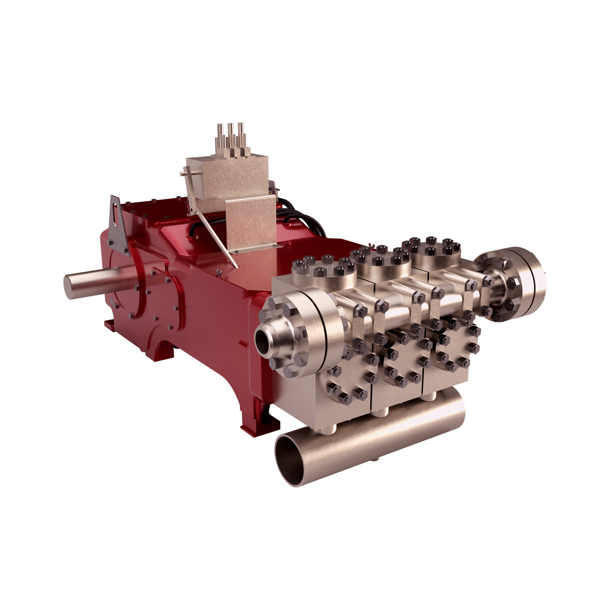
A triplex mud (or slush) pump has three horizontal plungers (cylinders) driven off of one crankshaft. Triplex mud pumps are often used for oil drilling.

10.Condensate or Duplex Heater (Liquid- Liquid Heater) heating surface, number of tubes, tube plate dia, pressure drop calculation formulas with online calculation sheet.
13. Formulas for calculating steam Percent cane and heating surface of the individual evaporator bodies in multiple effect evaporator with powerful online calculator.

2High hardness, wear resistance, it can resist high pressure mud of sharp or abrasive resistance of the solid particles grinding or scour, such as rock debris,quartz sands,iron ores,scrap iron.
I am often asked to visit plant sites to consult on problems regarding inadequate flow rates in two-pump systems. These plants are usually more than 10 years old, and the commissioning operators and engineers are no longer present. Plant output requirements have increased, and/or the equipment is simply old and less efficient. Either way, the desired outcome is to obtain more flow through the system.
In a typical scenario, someone observes there is an additional installed pump and decides the solution is to simply start and operate the second pump. To an untrained person who sees two pumps installed in the same system, it seems logical that operating the second pump in parallel will increase the flow. This may work in some instances but often does not. When the system is not designed for two (or more) pumps to operate at the same time (in parallel), it will not take long for both pumps to experience issues.
Two pumps set up to run individually and/or in parallel. In other words, pumps can run in parallel or separately, covering a wide range of expected flows.
To find the solution to the problem, the first thing I ask for is the system curve. The curve is often not available, so I work with plant personnel to calculate and develop the system curve. Once we overlay the system curve on the pump curves, the issue and possible solutions become readily apparent.
In many cases, the system designer may have designed the system to have one pump do all of the required work (100 percent duty pump) with a second pump (also known as the redundant pump, installed spare, 100 percent spare or backup pump) ready for operation so the first pump can be removed from service without disturbing the production process. The pumps and their associated motors and controllers are each designed for 100 percent duty.
The intersection of the single pump curve and the system curve should be near the best efficiency point (BEP) for the pump. In these types of cases, the piping system is not designed for both pumps to operate at the same time. The pipe size is typically too small to efficiently handle the higher flows and presents a huge friction loss if both pumps are operated. Another way to think of this situation is the system curve is steep—not flat—for two-pump operation.
If the system is designed for both pumps to operate at the same time, then the system curve will, by design, be flatter overall and present less friction. You can also think of undesired friction as wasted horsepower, which translates to higher electrical costs.
This column is not meant to explain in detail why one curve is steep and the other is flat. The important point to note is the steeper curves represent more friction loss as you attempt to pump more flow through the pipe. For this article, it is sufficient to say that if the system is designed for parallel pumping, the system curve will tend to be flatter.
Figure 1 depicts a properly designed system for parallel pump operations. With one pump operating (Intersection Point 1), the system curve remains relatively flat, and flow is X with corresponding head Y.
When the second pump is started (Intersection Point 2), the friction presented by the higher flows yields a slightly steeper system curve. While the flow will be more than X, please note that it will not attain magnitude 2X.
Figure 2 shows that if one of the pumps is an installed spare and both pumps are operated at the same time, then the additional flow is too much for the given pipe diameter, and the result is a high friction loss.
Looking at Operating Point 2, you can see that starting the second pump has yielded little additional flow. It could be in the range of X flow plus 10 percent, but in many cases it is even worse. This is why starting the second pump can actually kill both pumps.
In these situations, there will always be a strong pump and a weak pump. Even if the pumps were designed and manufactured to be identical, there is always some nuance in one of the pumps and in the system that will prevent the pumps from being identical.
The stronger pump will attempt to take the full load (as presented by the system). The stronger pump will run far right on its curve (a condition called runout) and have issues with vibration and cavitation (net positive suction head [NPSH] and flow angle incidence recirculation) that will manifest as damaged impellers as well as short-lived bearings and mechanical seals. At the same time, the weak pump will run at low to no flow and have similar issues because it is operating at the far left side of the curve. It is not uncommon for the stronger pump to develop sufficient pressure to close the discharge check valve on the weaker pump, consequently forcing it to operate at a shutoff head (zero flow rate).
Figure 3 shows the operation of Pump 1 (Intersection Point 1) and the subsequent parallel operation of Pump 2. A common misunderstanding is that if you start the second pump, the flow rate will double to Intersection Point 2. In reality, the actual operating point will be at Intersection Point 3. In a centrifugal pump system, the pump will always operate where the system curve dictates.
Pumps in a system that is not designed for parallel operation should not be operated at the same time except for brief intervals during switching operations. To do otherwise is likely to prematurely damage both pumps.
Often, a good system design is to have pumps in parallel because they can provide flexibility to match the flow to the load. This setup is also more reliable because it provides standby protection for a relatively high percentage of the full load in the event of one pump loss.
Different pump designs/models can operate together in parallel, but it is important that they have an identical shutoff head and similar specific speeds.
If the system is designed for parallel pumps, determine which pump is the stronger one by running one at a time and measuring the head at various flows. As a general rule, always start the weaker pump first.
You can overcome some of the mismatches in pump and system designs by using variable speed drives and carefully monitoring where each pump is on the curve, changing speeds as required to keep the load balanced.
When running one pump for small loads and then starting the second pump to pick up larger loads, do not let the first pump run out on its curve too far before the second pump is started. The first pump may be cavitating for some time before the second pump picks up. I see this happen often on systems designed to operate automatically. The designer often overlooks the NPSH margins at the right side of the curve.
Whether the pumps are in parallel or it is just two pumps in a one-pump system, I always recommend installing hour meters to track the operating hours. I have witnessed many mistakes resulting from decisions based on someone"s memory or record-keeping habits. Hour meters are inexpensive insurance. (Do you know when to change the oil in the pump?)
In a parallel pump system, whichever pump is started first must be capable of covering the full load presented by the system curve without overloading the driver or running out on its own curve.


 8613371530291