duplex mud pump formula quotation

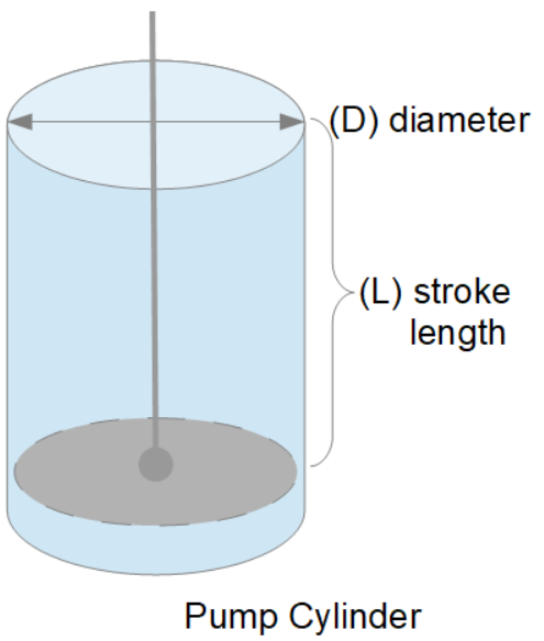
Rig pump output, normally in volume per stroke, of mud pumps on the rig is one of important figures that we really need to know because we will use pump out put figures to calculate many parameters such as bottom up strokes, wash out depth, tracking drilling fluid, etc. In this post, you will learn how to calculate pump out put for triplex pump and duplex pump in bothOilfield and Metric Unit.

Pump Output per Stroke (PO): The calculator returns the pump output per stroke in barrels (bbl). However this can be automatically converted to other volume units (e.g. gallons or liters) via the pull-down menu.
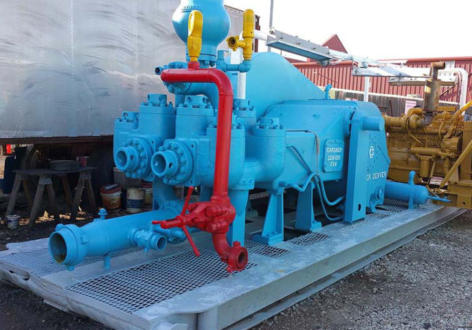
A triplex mud (or slush) pump has three horizontal plungers (cylinders) driven off of one crankshaft. Triplex mud pumps are often used for oil drilling.

When two (or more) pumps are arranged in serial their resulting pump performance curve is obtained by adding theirheads at the same flow rate as indicated in the figure below.
Centrifugal pumps in series are used to overcome larger system head loss than one pump can handle alone. for two identical pumps in series the head will be twice the head of a single pump at the same flow rate - as indicated with point 2.
With a constant flowrate the combined head moves from 1 to 2 - BUTin practice the combined head and flow rate moves along the system curve to point 3. point 3 is where the system operates with both pumps running
When two or more pumps are arranged in parallel their resulting performance curve is obtained by adding the pumps flow rates at the same head as indicated in the figure below.
Centrifugal pumps in parallel are used to overcome larger volume flows than one pump can handle alone. for two identical pumps in parallel and the head kept constant - the flow rate doubles compared to a single pump as indicated with point 2
Note! In practice the combined head and volume flow moves along the system curve as indicated from 1 to 3. point 3 is where the system operates with both pumps running
In practice, if one of the pumps in parallel or series stops, the operation point moves along the system resistance curve from point 3 to point 1 - the head and flow rate are decreased.

Pivotal to drilling and production, multiplex drilling pumps for sale have increased operational efficiency through the ability to ferry large volumes of fluid. At the heart of the quintuplex drilling pump developed by ShalePumps, lies a design that exploits the output of additional cylinders to curb pulsation variance.
Packed into physically smaller dimensions, the power packed quintuplex drilling pump assures a steady flow at the surface. With proven reliability, the quintuplex pump keeps the fluid in circulation, maintaining optimal pressure and volume, fetching debris effortlessly from the wellbore.
The featured quintuplex drilling pump combines structural superiority and engineering knowhow for enhanced life expectancy in continuous operations. Additionally, Measurement While Drilling (MWD) and Logging While Drilling (LWD) operations are substantially improved by the increased data transfer rate bandwidth.
The design accomplishes the added objective of extending life of downhole tools through operational precision of the quintuplex drilling pump. Improved rate of flow helps in cutting overall costs, dispensing with the need for many pumps. ShalePumps, possessing the technical expertise with an extensive range of proven solutions, takes great care to incorporate high quality components in every quintuplex drilling pump. The crankshafts, piston rods, liners, connecting rods, bearings etc are all of the highest quality. Each quintuplex drilling pump, despite the composition of high wear components, is guaranteed to offer longer continuous life.
ShalePumps is proud to bring the quintuplex design to a new level. Built to be smaller, lighter and smoother than any conventional triplex design. The addition of a fourth and fifth cylinder decreases pulsation variance to a minimal level. This increases accuracy and precision during LWD and MWD applications and increases the life expectancy of down-hole tools.

The installation of properly sized pulsation dampeners minimize vessel costs while protecting the pump and piping system and improving process efficiency and accuracy.
A pulsation dampener reduces or eliminates the variations in pressure and flow produced by reciprocating pumps. In many applications, low frequency pressure waves cause problems within a given piping system and/or process. Eccentric, cam-driven pumps are probably the most commonly applied for services that require pulsation dampening, e.g., metering pumps and reciprocating (power) pumps.
Pulsation dampeners are found in a variety of designs, but for our purposes we will focus on only gas-charged pulsation dampeners, which rely on a calculated volume of compressed gas, usually Nitrogen, which is alternately compressed and expanded in synchronization with the pump plunger to reduce or eliminate pressure pulsations. This gas volume is normally separated from the process fluid by a flexible membrane. Common membrane designs include elastomeric bladders, PTFE diaphragms, PTFE bellows or stainless steel bellows.
Pressure waves or pulses are a consequence of the alternating acceleration and deceleration of fluid velocity corresponding to the travel of the piston or plunger. The pattern and amplitude of these pulses varies with pump configuration, specifically the number and size of pistons, as well as fluid compressibility factors.
It is precisely the fluid volume above mean on the discharge cycle of each stroke, which induces these pressure pulsations into a piping system. The number of pistons offered by the pump-given that all are of identical diameter and equally phased-displace a known peak volume above mean. These constants may be influenced by fluid compressibility, but for the purpose of this explanation we’ll assume none at this point. A pulsation dampener absorbs only that portion of piston displacement above mean flow, and then stores it momentarily before discharging it during the portion of the cycle below mean flow (on the suction stroke).
A simplex pump displaces a volume of fluid above mean that is equal to about 60 percent of total displacement. A duplex pump displaces a lower fluid volume above mean, approximately half that of a simplex pump. Pumps of three or more pistons of equal diameter, stroke length and proportionally phased will always present a very small fluid volume above mean to the piping system. A triplex pump, for example, produces about a 4 percent peak, as long as fluid compressibility factors and pump efficiencies are not at issue.
These smaller fluid volumes are accounted for by the crank angle of each of the cylinders. Triplex pumps are offset by 120-deg. Quadruplex pumps are set apart at 90-deg offsets; quintuplex pumps are offset 72-deg, and so on. It is the resulting overlap in pulses that yield the smaller fluid volumes above mean.
Note: A pulsation dampener removes pulses only from the line downstream of the dampener-not upstream. That’s why it’s always recommended that discharge dampeners be installed as close to pump discharge nozzles as possible. In an application of a dampener for suction stabilization (reduction of acceleration head losses), it is the velocity gradient between the supply vessel and the suction nozzle that is minimized.
Let’s begin by defining the pump details required to properly size a pulsation dampener. We will use these values in a sample calculation to help clarify the process.
We recommend that the gas pre-charge pressure be set to 80 percent of system pressure. Lower pre-charge pressures may be specified elsewhere, but our experiences show that this is a low enough pressure to allow the membrane to move freely during operation while maximizing the gas volume. We will use 0.80 in the formula as the “% Pre-Charge” for 80 percent.
The result of the previous calculation is then divided by a constant. As noted previously, the constant is a function of pump configuration. We use a conservative 1.5 for simplex pumps, 2 for duplex pumps, and 7 for triplex pumps. Remember-if the fluid is compressible, then the constant may have to be adjusted downward.
Fluid volumes above mean are well within the range of these constants. The fluid pulse above mean flow from a simplex pump, for example, is about 60 percent. When we divide full stroke displacement by 1.5 the result is a conservative 67 percent. The divisor 7 that we use for triplex pumps allows for a nominal 14 percent fluid volume above mean. While 14 percent is far above the actual 4 percent produced by triplex pumps, the higher volume is an allowance for practical reasons, specifically size and nozzle limits. Otherwise, the result would be a very small dampener relative to pump size.
Some fluids are highly compressible, such as cryogenics, olefins, liquefied gases, anhydrous ammonia, etc. In these instances, the benefit of lower pulsations from multiple piston pumps may be somewhat compromised. Fluid compression occurs during the leading edge of the (eccentric) crank angle. Given sufficient pressure and a high enough compressibility factor, there may be little or no overlap of pulses at all-in which case, adjustments have to be made and pulsation dampeners with larger gas volumes should be selected.
By installing a properly-sized pulsation dampener, users can reduce or eliminate pipe shake, vibration and noise. The result is a continuous flow of product which is required in many metering, mixing and spraying applications. Reduced pressure pulsations minimize long-term damage to instrumentation and pump components while improving the accuracy of many flowmeters and increasing pump efficiency.

The design of a slurry pump is critical to making sure that the abrasive and often corrosive aspects of the slurry does not destroy the impeller. Additionally, slurry and sludge may contain large unforeseen solids that will inevitably clog many types of pumps. Since most centrifugal pumps have an impeller with a close tolerance to the volute, the abrasive and sometimes corrosive nature of the slurry will quickly wear the volute and ruin the tolerance. This, in turn, causes the pump to lose its suction capability. This causes massive downtime with slurry pumps along with costly maintenance and spare parts.
For this reason, the EDDY Pump is ideal for slurry pumping applications. The EDDY Pump does not have an impeller, but instead a rotor that does not have any critical tolerances. This allows it to pump slurry at rates of 30% and solids up to 12 inches. This is far more than what centrifugal pumps can handle without any failure or need to change wear parts.

GDEP is the original creator of the drilling pump and continues to set the standard for durable, high-quality drilling pumps that can withstand the world’s toughest drilling environments. Starting with our PZ7 and rounding out with the market"s most popular pump, the PZ1600, our PZ Series of pumps are the perfect choice for today"s high-pressure drilling applications.


 8613371530291