
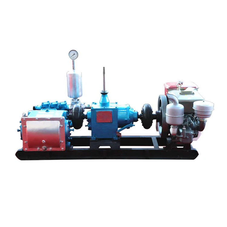
duplex mud pump operation free sample

AN OPERATIONAL SAFETY RELIEF VALVE MUST BE INSTALLED IN THE DISCHARGE LINE BETWEEN PUMP AND ANY OTHER PIPE FITTINGS. THIS RELIEF VALVE MUST BE SET AT THE RECOMMENDED RELIEF PRESSURE DESIGNATED ON THE PUMP APPLICATION TAG. CATASTROPHIC DESTRUCTION OF PUMP, PIPING, OR PERSONAL INJURY MAY RESULT IF DISCHARGE LINES ARE CLOSED WHEN THE PUMP IS STARTED, OR AFTER THE PUMP IS RUNNING.
Gears, connecting rod bearings and crossheads in all geared piston type pumps are lubricated by splash from lubricant in the crankcase. Crankshaft bearings and pinion shaft bearings in series 1800, 1500, 1600, 1700, 1900, and 2600 pumps are also lubricated from this same oil in the crankcase by splash. Shaft bearings in Series 1550-C, 1654-C, 2000 and 2200 pumps and in pumps with Serial Number 24523 and below are sealed off from the crankcase lubricant by oil seals and run in a separate bath of oil retained in the respective bearing housing.
WARNING -The crankcase is drained after testing pump at the factory. Remove crankcase cover or crosshead guide hand hole cover and fill with sufficient lubricant before starting the pump for the first time.
Quantity and type of lubricant required to fill crankcase to proper level is shown below. For chain and sprocket driven pumps use an SAE 30 high grade mineral oil in Crankcase.
For herringbone gear driven pumps operating in average climates, use SAE 90EP, AGMA 5EP, or AGMA 6EP gear lubricants. Be sure, however, to use an EP lubricant that will not have a corrosive action on Bronze and that it contains rust, oxidation and foam inhibitors. multi-purpose multi-viscosity gear lubricants are UNSATISFACTORY for use in GASO pumps.
For worm driven pumps, use an SAE 140 EP Gear Lubricant. Running temperature of crankcase oil should not exceed 180 degrees Fahrenheit. If higher temperatures occur and mechanical fits are found to be correct the use of a separate oil cooler is recommended. In addition, SAE EP 140 Gear Lubricant should be placed in separate bath bearings on pump where they are standard.
LUBRICATION OF SHAFT BEARINGS IN SERIES 1550-C, 16540C, 2000 and 2200 - (AND FOR PUMPS #24523 AND BELOW) These pumps are equipped with inner oil seals on pinion shaft and crankshaft, so they run in a separate bath of SAE EP 90 Gear Lubricant or SAE 50 high grade motor oil or mineral oil. The correct amount of oil is put into the bearing housings when pump is shipped from factory, but a check should be made to see that none has leaked out or been removed. Proper oil level is even with pipe plug in lower part of bearing housing flange or cover plate.
Pumps with herringbone gears #24523 and up do not have inner oil seals installed for the pinion and crankshaft bearings as standard equipment however, you pump may have these seals installed as special equipment. if your pump has inner oil seals installed, the amount of oil required for the crankcase is as follows:
To check for wear, place a wrench on the top connecting rod bolt and shake the rod parallel to the crankshaft. (The pressure must be relieved from the liquid end of the pump so that the pump"s mechanism is free to move.) If the rod bearing moves without resistance, the bearing may be too loose and need adjusting. If the bearing does need adjusting, remove shims until you cannot shake the rod, then add .005"" shims one at a time until there is a little side movement. Be sure to torque rod bolt nuts to proper value for each adjustment. (NOTE: If you are making this adjustment after having had the crossheads out, be sure that the oil holes in the rod are pointing up. The ""up"" side is indicated by matching numbers stamped on the cap and rod at the split between them. These numbers should be the same on each rod and should be on the top side of the crankshaft.) Turn the shaft by hand and if there is any hard drag or tight spots in the bearing, add another .005"" shim. After this bearing is properly adjusted, loosen bolts a few turns and repeat the above operation on the other bearings. After all bearings have been adjusted, torque all connecting rod bolt nuts back to proper amount. Again turn the pump by hand to check for excessive drag and tight spots. If none, the pump should then be ready for operation.
If the pump cannot be rotated by hand due to the drive being enclosed, the bearings may be completely adjusted by shaking the bearing on the shaft as stated above. Care must be taken not to over-tighten the bearings since they cannot be checked by rotating the pump by hand. When bearings are adjusted by this method, they must be watched carefully for overheating when the pump is put into operation.
Alternatively, plastic gauge strips, found in most parts stores may be used to adjust these bearings. It is usually better to have a bearing a little too loose than too tight. A slightly loose bearing will cause very little trouble because of the slow operating speeds of the pump, but a tight bearing will overheat and the babbitt may melt or pull. with experience, an operator can tell by feel when the bearings are properly adjusted. Normal precautions must be taken to insure cleanliness of parts upon their assembly. All wrenches used in adjusting these bearings are standard wrenches.
Bearings in the crosshead end are bronze bushings. To replace these bushings, remove connecting rod and crosshead assembly from pump. Press out the crosshead pin, and then remove and replace bushing. After the new bushing has been pressed into the connecting rod, it should be reamed for a loose fit on the crosshead pin as follows: .002"" for pumps Series 1500, 1800, and 1700, .0025"" for pumps Series 1600, and .004"" for pumps Series 2600.
Crankcase bearings for Series 1800, 1500, 1600, and 1700 pumps should have an end play in the crankshaft of: .001"" to .003"" for 1800 pumps .002"" to .004"" for 1500 pumps & 1600 pumps .003"" to .005"" for 1700 pumps
This end play is measured when pump is cold to allow for expansion due to heat under operating conditions. Bearings may be adjusted from one side only. To adjust bearings for end play, disconnect connecting rods, remove several shims (more than necessary) from under the bearing housing, tighten up on crankshaft bearing housings until bearings bind slightly when shaft is rotated by hand. Then measure the shim gap with a feeler gauge and add its equivalent plus from .001"" to .003"" of shim (for normal clearance) and tighten up on crankshaft bearing housing cap screws.
Crankshaft bearings for series 2600 Pumps have a .012"" to .013"" pre-load. To get this pre-load, try different thicknesses of shims until a slight drag is felt while rolling the shaft and then remove .012"" to .013"" of shims. When necessary to install new bearing cones on crankshaft, heat them in oil at 280 degrees Fahrenheit for easy installation. Be sure they are firmly against the shoulder on the crankshaft.
Please note: Improper application of heat to these bearings during their installation in GASO pumps will automatically revoke the warranty on the bearings. It is suggested that the procedures outlines above be closely followed when changing bearings. PINION SHAFT BEARINGS - The pinion shaft bearings are self-contained ball or roller bearings and have no adjustment for wear. Their load ratings are far above the load applied and will therefore have very little wear if properly lubricated.
Although pumps may run backwards without adversely affecting operation, always run them faster than 75 strokes per minute or install inner oil seals for pinion shaft and crankshaft bearings.
In worm-driven pumps, the main or ring gear, is of special nickel alloy bronze with internal flange for bolting to center disc of crankshaft. The driving worm and shaft is one piece, of chrome nickel steel, hardened and ground. This worm and shaft is removable through the end of worm case toward the liquid end of pump but it will first be necessary to remove the flexible coupling, stuffing box, and thrust bearing jam nut from other end of shaft. The thrust bearings will slide off when shaft is withdrawn.
Series 1550-C and 1654-C pumps use quadruple row internal sprockets with specially made heavy duty quadruple row chain. The driving pinion shaft and sprocket is one piece with Nitride Hardened sprocket teeth.
The piston rod stuffing boxes in power end of pump are packed at the factory. The purpose of this packing is to wipe the piston rod clean and thus prevent contamination of lubricant in the crankcase and also to prevent loss of oil from the crankcase. Adjust this packing by evenly tightening the packing gland cap screws until leakage is minimized.
Over a period of time, beginning may, 1978, all liquid end bodies for Duplex Piston Pumps were gradually redesigned to accept an O-ring mounted in a bevel at the opening of the valve covers, cylinder heads and stuffing boxes. This re-design allowed the flange of the valve cover, cylinder head, or stuffing box to fit metal-to-metal with the liquid body. Prior to this re-design most of these liquid ends were counter-bored to accept a flat gasket which caused a gap between the flanges of the valve covers, cylinder head, or stuffing boxes and the liquid end. BEFORE YOU REPAIR YOUR PUMP, MAKE A VISUAL CHECK TO SEE WHAT TYPE OF VALVE COVER, CYLINDER HEAD, AND STUFFING BOXES ARE ON THE PUMP.
The list of serial numbers below will serve as a general guide to the first pumps fitted with o-rings, but does not guarantee that your pump has them. You must check your pump before ordering parts for it. The first number is the pump serial number, the second number is the liquid end serial number:
Liquid end stuffing boxes on a new pump must be packaged by the user before the pump is put into service. The necessary packing will be found in small sacks packed in a box with other pump accessories. Standard packing consists of lip type packing rings. These function best when not squeezed up too tight. Special packing sometimes furnished consists of square graphited duck and rubber packing rings. These require more pressure to seal off fluid satisfactorily, but care should be exercised to avoid over-tightening. Good practice is to let packing leak slightly.
Standard pistons for crude oil service consist of cast iron or steel bodies with special patented cast iron porous chrome faced piston rings. Cast iron or steel piston bodies with nylon glass filled piston rings are furnished pumping crude oil products. Cup type pistons are furnished for pumping saltwater and rubber inserted pistons are used for slush and cementing service.
To replace pistons, remove crosshead jam nuts and power end and liquid end stuffing box glands and packing. Remove cylinder heads and pull rod, piston and liner through front of liquid end. Install new pistons, rings or cups is required. Insert pistons on to rod and into liners, oriented with front of piston toward flange end of liner. Install new liner gasket, and slip liner, piston and rod assembly into pump. Be sure to slip packing glands over rod before pushing rod thru power end stuffing box. Run crosshead jam nut onto rod as far as possible, positioned so flat face of nut will bear upon face of crosshead. Run rod into crosshead until jam nut touches crosshead, then tighten jam nut against crosshead. Be sure all mating surfaces are dry and clean before tightening nuts against pistons or crossheads. Note: torque all nuts holding pistons to rod to 7.200 in.-lbs.
Holding liner in place, roll pump one complete revolution to verify that piston is centered in the liner (end of cast iron piston may stroke out of liner), and adjust as necessary by repositioning the crosshead jam nut on the rod. Once centered, install the packing, glands, and cylinder heads. (See instructions for tightening liner set screws below.) Slush type pistons generally require more frequent attention than other types of pistons.
standard liners for crude oil service are cast iron. Liners for saltwater service are corrosion resistant material. Hardened steel liners are recommended for slush pump service. Always use new gaskets when changing liners.
There are four Liner Set Screws with jam nuts in each cylinder head. These are to hold the liner against the liner gasket. When installing cylinder head, back the liner set screws out a little and then tighten all nuts on cylinder head studs first. Be sure to work around the cylinder head from nut to nut until all are tightened evenly. Then tighten set screws against the liner, torque to 2880 in.-lbs. with the exception of Fig. 1849 pumps which are torqued to 2400 in.-lbs. again working evenly. Lastly, tighten the jam nuts on these set screws. Be sure that packing or lead gasket is in the cupped space on underside of jam nut.
Standard equipment for crude oil service consists of hardened and ground steel wing guided valves and seats. Bronze wing guided valves and seats are usually furnished for fresh or saltwater service. Tops of valve stems are slotted so that valve can be rotated in the pump to regrind valve and seat faces with grinding compound. When worn too badly, they can be removed and faced off in a lathe.
Slush pump valves require frequent replacement of rubber inserts due to the very abrasive material being pumped. Valves and seats should be inspected before starting and when finishing any drilling job. When replacing valve seats, clean valve seat and mating taper in liquid end with a cleaner that does not leave an oil film or residue. Wipe with a clean, dry rag.
Note: If the pump is EVER overloaded (loaded above maximum recommended published pressures) or if a stud EVER fails for any reason whatsoever, REPLACE ALL STUDS IN THE LIQUID BODY BEFORE USING THE PUMP AGAIN.
Pumps are equipped with O-Ring gaskets for valve covers, cylinder heads, and stuffing boxes, and with flat fiber gaskets for suction and discharge flanges. Separate lantern rings and ""tattle-tale"" packing is furnished as gaskets for liners in recently manufactured slush fitted pumps, while pumps fitted for other applications are equipped with spacers and flat fiber liner gaskets. Always be sure that all gasket surfaces are smooth and dry and free of any particles which would scratch or otherwise interfere with efficient operation of the gasket.
Piston displacement and recommended working pressure for continuous duty and with various size liners are shown in the current GASO catalog. When pumping relatively incompressible liquids, volumetric efficiency of pump when valves and liners and pistons are in good shape should be from 95% to 96%. If actual output of pump does not equal 95% of displacement figures shown at the respective speeds, cause o£ trouble may be foreign matter lodged under valve, bad valve facing, worn liners, worn piston rings, or blown liner gasket. Too small a suction line may also be cause of shortage. SUCTION LINES -- (REFER TO DIAGRAM)
Flush suction lines thoroughly before starting pump. Always provide ample capacity suction lines to the pump. This is the first requisite when installing a GASO pump. The pump cannot function properly if an inadequate quantity of fluid is furnished it. For suction lines leading directly to the pump, select a size line so that the velocity of the fluid will not exceed 12 feet per second, or one that is two sizes larger than the pump suction connection, whichever gives the slower line velocity. The last to to 15 feet of this line is preferably flexible hose and should always be connected to the pump inlet with an eccentric reducer (with straight portion on top). Always size ""headers"" feeding more than one pump so that the maximum velocity in the header with all pumps running will not exceed 1 foot per second.
NEVER USE PLUG-TYPE VALVES IN A SUCTION LINE. USE FULL OPENING VALVES. Keep the number of turns to a minimum. When turns are required, use long radius ells. In pumping gasoline or light volatile liquids such as butane and propane, design your system so that the positive suction head at the pump is at least 35 pounds per square inch (psi) above the vapor pressure of the fluid. When pumping water or average crude oils, 10 to 15 psi gauge pressure at the pump will usually be sufficient if pump speed does not exceed 54 RPM. If pump is running at higher speeds, provide for a minimum additional pressure of 15 psi at the pump inlet. Always connect to two sides of pumps with multiple suction inlets. This will help insure proper filling of the pump. If unable to connect to two sides, use a properly sized suction stabilizer, mounted and charged according to instructions with stabilizer.

Rig pump output, normally in volume per stroke, of mud pumps on the rig is one of important figures that we really need to know because we will use pump out put figures to calculate many parameters such as bottom up strokes, wash out depth, tracking drilling fluid, etc. In this post, you will learn how to calculate pump out put for triplex pump and duplex pump in bothOilfield and Metric Unit.
The 2,200-hp mud pump for offshore applications is a single-acting reciprocating triplex mud pump designed for high fluid flow rates, even at low operating speeds, and with a long stroke design. These features reduce the number of load reversals in critical components and increase the life of fluid end parts.
The pump’s critical components are strategically placed to make maintenance and inspection far easier and safer. The two-piece, quick-release piston rod lets you remove the piston without disturbing the liner, minimizing downtime when you’re replacing fluid parts.
If you run a mud rig, you have probably figured out that the mud pump is the heart of the rig. Without it, drilling stops. Keeping your pump in good shape is key to productivity. There are some tricks I have learned over the years to keeping a pump running well.
First, you need a baseline to know how well your pump is doing. When it’s freshly rebuilt, it will be at the top efficiency. An easy way to establish this efficiency is to pump through an orifice at a known rate with a known fluid. When I rig up, I hook my water truck to my pump and pump through my mixing hopper at idle. My hopper has a ½-inch nozzle in it, so at idle I see about 80 psi on the pump when it’s fresh. Since I’m pumping clear water at a known rate, I do this on every job.
As time goes on and I drill more hole, and the pump wears, I start seeing a decrease in my initial pressure — 75, then 70, then 65, etc. This tells me I better order parts. Funny thing is, I don’t usually notice it when drilling. After all, I am running it a lot faster, and it’s hard to tell the difference in a few gallons a minute until it really goes south. This method has saved me quite a bit on parts over the years. When the swabs wear they start to leak. This bypass pushes mud around the swab, against the liners, greatly accelerating wear. By changing the swab at the first sign of bypass, I am able to get at least three sets of swabs before I have to change liners. This saves money.
Before I figured this out, I would sometimes have to run swabs to complete failure. (I was just a hand then, so it wasn’t my rig.) When I tore the pump down to put in swabs, lo-and-behold, the liners were cut so badly that they had to be changed too. That is false economy. Clean mud helps too. A desander will pay for itself in pump parts quicker than you think, and make a better hole to boot. Pump rods and packing last longer if they are washed and lubricated. In the oilfield, we use a petroleum-based lube, but that it not a good idea in the water well business. I generally use water and dish soap. Sometimes it tends to foam too much, so I add a few tablets of an over the counter, anti-gas product, like Di-Gel or Gas-Ex, to cut the foaming.
Maintenance on the gear end of your pump is important, too. Maintenance is WAY cheaper than repair. The first, and most important, thing is clean oil. On a duplex pump, there is a packing gland called an oil-stop on the gear end of the rod. This is often overlooked because the pump pumps just as well with a bad oil-stop. But as soon as the fluid end packing starts leaking, it pumps mud and abrasive sand into the gear end. This is a recipe for disaster. Eventually, all gear ends start knocking. The driller should notice this, and start planning. A lot of times, a driller will change the oil and go to a higher viscosity oil, thinking this will help cushion the knock. Wrong. Most smaller duplex pumps are splash lubricated. Thicker oil does not splash as well, and actually starves the bearings of lubrication and accelerates wear. I use 85W90 in my pumps. A thicker 90W140 weight wears them out a lot quicker. You can improve the “climbing” ability of the oil with an additive, like Lucas, if you want. That seems to help.
Outside the pump, but still an important part of the system, is the pop-off, or pressure relief valve. When you plug the bit, or your brother-in-law closes the discharge valve on a running pump, something has to give. Without a good, tested pop-off, the part that fails will be hard to fix, expensive and probably hurt somebody. Pop-off valve are easily overlooked. If you pump cement through your rig pump, it should be a standard part of the cleanup procedure. Remove the shear pin and wash through the valve. In the old days, these valves were made to use a common nail as the shear pin, but now nails come in so many grades that they are no longer a reliable tool. Rated shear pins are available for this. In no case should you ever run an Allen wrench! They are hardened steel and will hurt somebody or destroy your pump.
One last thing that helps pump maintenance is a good pulsation dampener. It should be close to the pump discharge, properly sized and drained after every job. Bet you never thought of that one. If your pump discharge goes straight to the standpipe, when you finish the job your standpipe is still full of fluid. Eventually the pulsation dampener will water-log and become useless. This is hard on the gear end of the pump. Open a valve that drains it at the end of every job. It’ll make your pump run smoother and longer.

When choosing a size and type of mud pump for your drilling project, there are several factors to consider. These would include not only cost and size of pump that best fits your drilling rig, but also the diameter, depth and hole conditions you are drilling through. I know that this sounds like a lot to consider, but if you are set up the right way before the job starts, you will thank me later.
Recommended practice is to maintain a minimum of 100 to 150 feet per minute of uphole velocity for drill cuttings. Larger diameter wells for irrigation, agriculture or municipalities may violate this rule, because it may not be economically feasible to pump this much mud for the job. Uphole velocity is determined by the flow rate of the mud system, diameter of the borehole and the diameter of the drill pipe. There are many tools, including handbooks, rule of thumb, slide rule calculators and now apps on your handheld device, to calculate velocity. It is always good to remember the time it takes to get the cuttings off the bottom of the well. If you are drilling at 200 feet, then a 100-foot-per-minute velocity means that it would take two minutes to get the cuttings out of the hole. This is always a good reminder of what you are drilling through and how long ago it was that you drilled it. Ground conditions and rock formations are ever changing as you go deeper. Wouldn’t it be nice if they all remained the same?
Centrifugal-style mud pumps are very popular in our industry due to their size and weight, as well as flow rate capacity for an affordable price. There are many models and brands out there, and most of them are very good value. How does a centrifugal mud pump work? The rotation of the impeller accelerates the fluid into the volute or diffuser chamber. The added energy from the acceleration increases the velocity and pressure of the fluid. These pumps are known to be very inefficient. This means that it takes more energy to increase the flow and pressure of the fluid when compared to a piston-style pump. However, you have a significant advantage in flow rates from a centrifugal pump versus a piston pump. If you are drilling deeper wells with heavier cuttings, you will be forced at some point to use a piston-style mud pump. They have much higher efficiencies in transferring the input energy into flow and pressure, therefore resulting in much higher pressure capabilities.
Piston-style mud pumps utilize a piston or plunger that travels back and forth in a chamber known as a cylinder. These pumps are also called “positive displacement” pumps because they literally push the fluid forward. This fluid builds up pressure and forces a spring-loaded valve to open and allow the fluid to escape into the discharge piping of the pump and then down the borehole. Since the expansion process is much smaller (almost insignificant) compared to a centrifugal pump, there is much lower energy loss. Plunger-style pumps can develop upwards of 15,000 psi for well treatments and hydraulic fracturing. Centrifugal pumps, in comparison, usually operate below 300 psi. If you are comparing most drilling pumps, centrifugal pumps operate from 60 to 125 psi and piston pumps operate around 150 to 300 psi. There are many exceptions and special applications for drilling, but these numbers should cover 80 percent of all equipment operating out there.
The restriction of putting a piston-style mud pump onto drilling rigs has always been the physical size and weight to provide adequate flow and pressure to your drilling fluid. Because of this, the industry needed a new solution to this age-old issue.
As the senior design engineer for Ingersoll-Rand’s Deephole Drilling Business Unit, I had the distinct pleasure of working with him and incorporating his Centerline Mud Pump into our drilling rig platforms.
In the late ’90s — and perhaps even earlier — Ingersoll-Rand had tried several times to develop a hydraulic-driven mud pump that would last an acceptable life- and duty-cycle for a well drilling contractor. With all of our resources and design wisdom, we were unable to solve this problem. Not only did Miller provide a solution, thus saving the size and weight of a typical gear-driven mud pump, he also provided a new offering — a mono-cylinder mud pump. This double-acting piston pump provided as much mud flow and pressure as a standard 5 X 6 duplex pump with incredible size and weight savings.
The true innovation was providing the well driller a solution for their mud pump requirements that was the right size and weight to integrate into both existing and new drilling rigs. Regardless of drill rig manufacturer and hydraulic system design, Centerline has provided a mud pump integration on hundreds of customer’s drilling rigs. Both mono-cylinder and duplex-cylinder pumps can fit nicely on the deck, across the frame or even be configured for under-deck mounting. This would not be possible with conventional mud pump designs.
The second generation design for the Centerline Mud Pump is expected later this year, and I believe it will be a true game changer for this industry. It also will open up the application to many other industries that require a heavier-duty cycle for a piston pump application.
This invention relates generally to piston pumps for the water well drilling industry, and more particularly to a hydraulic cylinder powered double acting duplex piston pump.
Double acting duplex piston pumps are well known and have been used in the water well drilling industry for many years. Typically they employ a crankshaft and flywheel driven in various ways, a reciprocating engine or a hydraulic motor being examples. Typically, they are heavy units with a large component of cast iron. Today"s well drilling trucks carry lengths of drilling pipe, as well as derricks, motors, pumps of various kinds, and the “mud” pump. The current double acting duplex piston pumps with crankshaft and flywheel, being very heavy, contribute significantly to the weight and space requirements of the truck. They impact the ability of a truck to meet federal highway weight restrictions. Also, the mechanical crank throw design imparts a variable speed to the mud pump piston. In such designs, the piston is either accelerating or decelerating during a large part of its design stroke. So the piston operates at its full design capacity during only a portion of the stroke. Therefore, it is an object of the present invention to provide a duplex piston pump useful as a mud pump on a water well drilling machine, but without a motor, crankshaft, flywheel, gearing, and/or belts, for a significant weight reduction.
Described briefly, according one embodiment of the present invention, a mud pump is provided with two working cylinders for pumping mud, and two sets of double-acting hydraulic driving cylinders. One set of two driving cylinders has the piston of each connected to the piston of one double-acting mud pump cylinder. The other set of two driving cylinders has the piston of each connected to the piston of the other double-acting mud pump cylinder. The connection of a set of driving cylinder pistons to the mud pump piston is through a member which allows side-by-side, or over and under parallel arrangement of the driving cylinders and mud pump cylinders, so the overall length is minimal. An electro-hydraulic control system is provided to coordinate the action of the pump driving cylinders with the mud pumping cylinders for contributing to steady flow of mud from the mud pump.
FIG. 2 is a schematic elevational view of one of the two pump assemblies of the duplex piston pump according to one embodiment of the present invention.
FIG. 3 is a schematic diagram of a system according to the illustrated embodiment and showing both of the duplex mud pump cylinders, with one of two hydraulic driving cylinders for each of the mud pump cylinders, and including an organization of hydraulic flow divider, rod position sensing, proximity-type electrical switches and associated electrical relays for solenoid-operated hydraulic fluid directing spool valves associated with the hydraulic cylinders.
FIG. 6 is an example of a flow chart relating mud pump speed to mud pump output volume capacity and hydraulic driving oil volume requirement for a pump according to the illustrated embodiment of the present invention.
FIG. 7 is a diagram showing theoretical pump driving cylinder piston performance of the two sets of mud pump driving cylinders operating according to the illustrated embodiment of the present invention.
FIG. 1 shows, schematically, a normal environment in which the mud is pumped by duplex piston pump 5 of the present invention from the chip separation tank 6 through the pump and the discharge the line 7 into the top of drill pipe 8 and down in the drill pipe and out into the well casing at the drill bit 10. The mud flows upward through the casing and back into the separation tank 6. The pump itself includes two mud pumping cylinders 1 and 2 fixed relative to a base 3 (FIGS. 5A and 5B) by mounting to four housings 4L, 4F, 4R and 4B which are fixed to the base.
As suggested above, according to the present invention, an all-hydraulic drive for the two mud-pumping pistons in cylinders 1 and 2 is achieved. For that purpose, and referring to FIG. 3, a variable volume hydraulic pump P is used. It can be set, for example, at a rate of 36 gallons per minute at 1,000 psi. A motor M can be used to drive such a pump, and such pumps and drives for them are known in the art and readily available. The pump output is fed to a flow divider D. This is not merely a device to split the flow. Instead, it has a piston inside which will shift in either direction to the extent necessary as it tries to be sure that the exact same volume flow rate is delivered at both output ports of the flow divider. An example of such a flow divider is Model MH2FA by Rexroth Worldwide Hydraulics.
Before proceeding further with this description, it is important to understand that each half of the duplex piston pump includes a double-acting mud pump cylinder and piston assembly. FIG. 2 shows one of the halves including mud pump cylinder 1. The other half, including a mud pump cylinder and associated hydraulic driving cylinders is identical. FIG. 5A shows, schematically, a rod end view of the duplex piston mud pump 5 including the mud pump cylinders 1 and 2 and associated driving cylinders of both halves.
The mud pump cylinders and their associated driving cylinders may be fixed relative to each other and mounted to the base 3 by any suitable means. The schematics of FIGS. 5A and 5B show, as an example, the four valve housings 4F, 4L,4B and 4R fixed to base 3. Except for right and left ports, each of these housings is the same as the others, and includes therein a chamber such as 41C having an opening 41A communicating with a port of a mud pump cylinder such as cylinder 1 or 2. Each chamber 41C also has two other openings. One of them is fitted with a one-way, spring loaded outlet valve such as 16 to enable mud to move from chamber 41C into the upper end of housing 4L and out through port 41D into the discharge plenum 7A. The other opening 41E of chamber 41C is fitted with a spring loaded inlet valve such as 14 communicating with the lower end of housing 4L and enabling mud entering suction inlet 6A of the mud suction manifold 6B to enter through port 41E in housing wall and into chamber 41C. The mud pump cylinders are attached to their respective valve housings in conventional manner with the ports of the cylinders communicating with the respective chambers of the housings.
Referring now to FIGS. 2 and 5A and 5B together, FIG. 2 shows schematically mud pump cylinder 1 and inlet and outlet valves 11 and 12, respectively, associated with the pump port at one end of cylinder 1, and inlet and outlet valves 14 and 16, respectively, associated with the pump port at the opposite end of cylinder 1, the rod-end of the cylinder. In practice since there would normally be only one port at each end of the cylinder, the valves would be in the housings 4L and 4F for cylinder 1. There is a packing gland 17 at the rod-end of the cylinder. In FIG. 5B the top of housing 4L is cut away to show discharge valve 16. Suction or inlet valve 14 below chamber 41C is shown larger in dashed lines to be able to see it in FIG. 5B, as it is the bottom of chamber 41C, FIG. 5A.
According to one feature of this invention, there are two hydraulic driving cylinder/piston assemblies 19 and 21 arranged in a way to drive the mud pump piston 1P in cylinder 1. As suggested above, cylinders 1, 19, and 21 are all connected relative to each other by some suitable means (brackets and/or clamps, for example) so that they are longitudinally immovable relative to one another. This is represented schematically for both sets of mud pump and driving cylinders at the valve housing 4L, 4R and associated inlet and outlet and base in FIGS. 5A and 5B, to which all of the six cylinders of both halves of the duplex pump are rigidly, but removably connected. Each of the two driving cylinder assemblies for piston 1P has a piston rod such as 19R and 21R bolted to a rod connector plate 22. Each rod may extend through the piston and exit the driving cylinder at the end opposite the plate-connected rod end, as indicated at 19S and 21S. The respective pistons 19P and 21P are affixed and sealed to the rod in a suitable way and may be of any suitable construction. Of course, the same effect may be achieved using separate colinear rods secured to opposite faces of the pistons. The piston rods 19R and 21R of the driving cylinders for mud pump cylinder 1, and rod 1R of the mud pump cylinder 1 itself, are bolted to the rod connector plate 22. Each of the rods 19R, 19S and 21R, 21S is supported at opposite ends of the respective cylinder by bearings and seals at 19B and 21B, respectively. Using double rod cylinders provides equal working area on the two sides of the piston, enabling equal oil flow and thrust capacity in both directions of piston travel. One or the other of the driving cylinder rods for mud pump cylinder 1 is associated with a set of proximity sensing switches A-1, B-1, C-1, and D-1 to operate a relay to shift a hydraulic solenoid valve spool to control hydraulic fluid to and from the set of two driving cylinders 19 and 21 to drive the mud pump 1. The same kind of arrangement is provided for mud pump cylinder 2. For each set, the driving cylinder which has the associated proximity switches, may be referred to hereinafter from time-to-time, as the control cylinder.
In this particular arrangement, only as an example of cylinder and rod size, the mud pump cylinder may be six inches in diameter with a twelve inch stroke, using the pistons of two driving cylinders of two inch diameter each to drive the one mud pump piston. A significant advantage can be achieved by making the rods of the driving cylinders larger in diameter (1.375 inches, for example) than that of the mud pump cylinder rod (1.25 inches, for example). It enables use of larger and longer wearing bearings in the driving cylinders, and enables the use of a relatively small piston rod and packing gland 17 in the mud pump cylinder, thus minimizing exposure to wear of the packing gland. The combination of the large diameter rods in the driving cylinders, fixed to a rigid rod connector plate 22 to which the mud pump cylinder rod is bolted, contributes to a very rigid structure. It avoids the necessity of a very long arrangement and long piston rod spans which would be necessary if the mud pump cylinder was driven by a single piston in a hydraulic cylinder on the same longitudinal axis. That would require a more complicated bearing arrangement to support the mud pump cylinder rod. In the present arrangement, the cylinder rod bearings are relatively close to the mud pump packing gland, helping extend the life of the gland by minimizing radial working and resulting loading of the mud pump rod on the packing gland. Also, with the present arrangement, the driving cylinder rods are in tension when the mud pump rod is in compression, which reduces the bending moment.
The proximity sensor switches A-1 through D-1 are responsive to movement of an actuator such as flange 19F on rod 19R, 19S. These switches may be normally-closed or normally-open switches as a matter of convenience in the construction of the circuitry. It should be understood, of course, that the other half of the duplex double acting pump assembly which includes cylinder 2, has driving cylinders such as 29 and 31 associated with it, and proximity switches associated with the piston rod of one (29, for example) of those driving cylinders, (shown in FIGS. 3 and 5A) in the same manner as for the assembly shown in FIG. 2. The position of the piston in cylinder 1 is preferably in a different location and/or it is moving in a different direction, from that of the piston in cylinder 2.
Referring now to FIG. 3, mud pump cylinder 1 and mud pump cylinder 2 are shown schematically, as is one cylinder of each set of two driving cylinders for each of the two mud pump cylinders 1 and 2, respectively. Since the mud pump cylinders are virtually identical and the two driving cylinders of the set for each of the mud pump cylinders are virtually identical, a description of one driving cylinder and associated controls will suffice for both.
The output from flow divider D enters the center input port of a two-position, solenoid-actuated, spring-return hydraulic valve V-1. This valve is electrically coupled to a relay switch R-1 which is bi-stable and electrically coupled to the proximity sensor switch A-1. An example of a suitable relay is No. 700-HJD32Z12 by Allen-Bradley. It is a DPDT latching relay. One switched position of this relay switch R-1 causes the solenoid to be energized to open the valve and supply pressurized oil from valve V-1 through line L-1 to the one end of cylinder 19 and likewise cylinder 21 of FIGS. 2 and 5 to drive the pistons in the direction of the arrow 23. This occurs in both driving cylinders 19 and 21, so rod 13R, being mechanically fixed to the two driving cylinder rods 19R and 21R by rod connector plate 22, is likewise driven in the direction of the arrow 23. When relay R-1 is reset by a signal from another proximity switch which can be recognized upon study of FIGS. 4A through 4D, it de-energizes the solenoid for valve V-1, enabling the spring therein to return the solenoid to position where the supply to the cylinder 19 is through line L-2, to reverse the direction of the piston in that cylinder and its companion driving cylinder, thus reversing the direction of the mud pump piston 1P. Whichever side of the piston is not pressurized at any time is enabled to dump through the valve V-1 to sump S-1. Essentially the same arrangement exists for control and drive of mud pump cylinder 2. In this instance, the proximity switches are designated A-2, B-2, C-2 and D-2. The relay switch is R-2 and the control valve is V-2 operated by a solenoid. It should be mentioned at this point, however, that while the pistons in the driving cylinders for one of the mud pump cylinders are located in the same relationship to each other as the mud pump cylinder with which they are associated, they are typically out of phase with respect to the mud pump piston and pistons of associated drive cylinders of the other mud pump cylinder. This is intentional in an effort to be sure that the flow out of the mud pump assembly 5 is as stable and constant as possible. That is the goal to which the organization of the proximity switches and associated relay switches are directed. Also with reference to FIGS. 2 and 3, it should be mentioned that the supply lines L-1 and L-2 to cylinder 19 are larger than the lines from cylinder 19 to cylinder 21. This is because the lines from valve V-1 go directly to only one of the two driving cylinders and from that point, are directed to the other driving cylinder. Thus, the supply lines L-1 and L-2 must be large enough to drive both driving cylinders 19 and 21 with essentially equal pressure and volume capacity. This is shown schematically in FIG. 2 with lines B-1 and B-2 from cylinder 19 to cylinder 21.
Referring now to FIGS. 4A through 4D, along with FIG. 3, FIG. 4A is a simplified portion of FIG. 3. It includes a driving cylinder 19 for mud pump cylinder 1, and driving cylinder 29 for mud pump cylinder 2. It also shows the proximity switches A-1 and B-1 associated with the piston rod portion 19S of cylinder 19. Similarly, proximity switches A-2 and B-2 associated with the piston rod 29S of driving cylinder 29, are shown. The position of the rod 19S relative to rod 29S is only for purposes of example, as it is not expected that the pistons of cylinders 1 and 2 will ever be positioned at the same longitudinal location relative to each other unless they are passing as one goes in one direction and the other goes in the other direction. But the purposes of the proximity switches A-1 and B-1 is to limit the travel of the piston in the two directions. Thus, either the switch A-1 or the switch B-1 can set or reset relay R-1 to cause the valve V-1 to shift and switch the high pressure from valve V-1 to either line L-1 to move the driving piston and thereby the mud pump piston 1P to the right, or apply the high pressure to line L-2 and drive the driving piston and thereby, the mud pump piston 1P to the left. Regardless of which direction the mud pump piston is moving, it will be drawing mud from the chip separation tank 6 and discharging it to the manifold connected to discharge line 7. The arrangement and operation is true regarding driving cylinder 29 and the proximity switches and relay R-2 and valve V-2 associated with that piston rod 29S.
To assure that the pistons of the two mud pump cylinders are never at either end limit of their strokes simultaneously, two additional proximity switches C-1 and D-1 (FIGS. 4B and 4D) are added. Each of these can be located about 2 inches, for example, from the proximity switches A-1 and B-1 and functions in the same way as described above with respect to switches A-1 and B-1.
The control system of FIG. 4D provides the combination of components to achieve two objectives. The first, and probably the more important, is to insure that the set of power cylinders 19 and 21 for mud pump cylinder No. 1 will cycle independently of the set of power cylinders 29 and 31 for mud pump cylinder 2, providing a 12 inch stroke for each of the mud pump cylinder rods independently of the other rod. A scheme for accomplishing this is shown generally in FIG. 4A where the sensor A-1 or the sensor B-1 can energize the latching relay R-1 at opposite ends of the piston rod stroke.
Another objective is to build a system which will insure that the piston 1P for mud pump cylinder 1 does not reach the end of its individual stroke at the same time as the piston 2P for mud pump cylinder 2. That could occur when both pistons are side-by-side and going in the same direction (FIG. 4B, for example) or when they are phased 180 degrees apart, so going in opposite directions and nearing the ends of their strokes (FIG. 4C, for example). These conditions are more complex and are addressed by the additional components shown in FIGS. 4B and 4C.
In addressing this problem, it should be recognized that the mud pump pistons could arrive at the ends of their strokes at the same time even if not necessarily together mid-stroke, but they would probably have been together at least a short distance before they reached the ends of their strokes. In FIGS. 4B and 4C and the above description, a two inch distance from the end of the stroke is mentioned and shown, but this distance could be one inch or some other suitable distance. If the two pistons are together a short distance from the end of their strokes, it is likely that they would reach the end of their strokes at essentially the same time.
Since reaching the end of the stroke simultaneously for both mud pump pistons is not desirable, the present invention reverses one of the two pistons prior to reaching the normal end of the stroke. When one piston reverses, its stroke has been limited at 10 inches. This will place the two mud pump pistons out of phase for an extended period. For this purpose, the additional proximity switches C-1 and D-1 for piston rod 19S, and C-2 and D-2 for piston rod 29S, are added, as mentioned above. For the right combination of signals, to correctly use the proximity switches C-1, C-2, D-1 and D-2, additional relays R-3, R-4, R-5 and R-6 can be used. An example is a DP/DT, a stable (non-latching) relay by Siemens, Potter & Brumfield Division.
The combination of the foregoing components for the control functions as described above and shown in FIGS. 4A, 4B and 4C, results in the control component organization of FIG. 4D which is a consolidation of the systems of FIGS. 4A, 4B and 4C, to achieve the above-mentioned goals of having the power cylinder set for mud pump cylinder 1, cycle independently of the power cylinder set for mud pump cylinder 2, and avoiding the simultaneous arrival at the end of their strokes of mud pump piston 1 and mud pump piston 2. At this point it should be understood that specific implementation of controls is not limited to the above-described organization of proximity switches, activators for them, types of valves or relays, whether electrically or pneumatically controlled, or the specific organization of an electrical, pneumatic, or optical control circuit, for example, portions of which may be solid state discrete devices, or integrated circuit organizations, as it will depend largely on the preference of and choices by a control circuit designer and well within the skill of the art of one who understands the organization and intentions and implementation described above, according to the present invention.
Initially, in the practice of the present invention according to the illustrated embodiment, it is intended that valving and control as shown in FIG. 4D and described above, or in such other scheme as may be preferred, be used so that when a constant flow of hydraulic oil is delivered into the system by the hydraulic pump P, relatively constant mud flow from the double acting duplex mud pump will be possible. With the present invention, the flow divider D (FIG. 1) is truly a flow divider, attempting to deliver the same volume at both outlet ports. To do so, it attempts to adapt to any difference in operation of one of the mud pump pistons relative to the other, by adjusting the pressure. For example, if the piston rod packing in one mud pump cylinder is tighter on the rod than on the other mud pump cylinder, the flow divider spool centering springs will tend to move the spool in a direction attempting to establish the same amount of flow to both of the hydraulic oil driving cylinders. Also, when one mud pump driving cylinder set piston reaches the end of its stroke, what would otherwise appear to be a sharp rise in pressure to be handled by the flow divider, can be tolerated by the flow divider itself so as to avoid damaging mechanical or hydraulic shock. This effect is somewhat mirrored in FIG. 7 which shows in the solid lines, the wave form of pressure available from the mud pump cylinder 1 for one stroke cycle, that being a full stroke from left to right, and a full return stroke from right to left in FIG. 3, for example. The dashed wave form represents the available pressure from mud pump cylinder No. 2. In this illustration, the discharge pressure in cylinder 1 begins a sharp rise from 0 at point A to a maximum available pressure at point M and then drops sharply beginning at point N to 0 at point R. Then it rises on the opposite side of the piston sharply at point R to the same maximum level and then drops again to 0 at point S. Meanwhile, if the pistons of the two mud pump cylinders happen to be operating at 90° phase relationship, the available pressure from the cylinder No. 2 follows the dashed line. Both of these pressure “curves” are essentially a square wave, in contrast to the somewhat sinusoidal output of a conventional, crankshaft-driven duplex piston pump. At point A, when the pistons in the driving cylinders for cylinder 1 get to the end of their stroke, the hydraulic pressure on the driving pistons rises sharply until the pistons begin moving in the opposite direction. This is because of the fact that, when the pistons of either driving cylinder set reach the end of their stroke, and the related solenoid valve is shifting to change the direction of the piston, there is no flow of oil through this valve. With a constant input flow of oil, it must be re-routed to prevent pressure build-up in the system and popping pressure relief valve, and also to prevent a volume drop in the discharge of the mud pump. The flow divider D has tolerance to enable this temporary re-routing to the driving cylinders 29 and 31. At the same time, with the additional pressure on these cylinders driving pump 2, a pressure spike may result in mud pump cylinder 2 such as shown in the dashed line at A and R and S in FIG. 7. The spike could be at other locations, depending upon the phase relationship of the cylinder set for mud pump cylinder 1 and the cylinder set for mud pump cylinder 2. Thus with a less than 100% accuracy-style flow divider D, the excess oil from one shifting solenoid valve is routed to the other (open) solenoid valve and driving cylinder set, which increases in speed and keeps the mud pump discharge constant. The oil itself becomes an accumulator and pressure relief system, operating at the exact same pressure over the full range of the operating system and produces the effect of constant velocity pistons in the mud pump.
Since these driving pistons are not driven by a crank shaft, they operate at essentially constant velocity. In other words, whereas a piston driven by a rotating crank shaft moves according to a harmonic sine wave pattern, a piston driven according to the present invention defines essentially a square wave pattern. In a conventional pump where the piston is driven by a rotating crank shaft, the inlet and outlet valves must be designed and sized to permit maximum flow, which typically occurs at the time of maximum travel of the piston, which occurs when the crank pin axis and rotational axis of the crank shaft are in a plane perpendicular to the axis of the piston. In contrast with construction according to the present invention, the inlet and outlet valves are sized to a maximum flow which is essentially constant regardless of where the piston is during its stroke, and which is only limited by the flow available from the flow divider. Therefore, as an example, where a conventional 5×6 mechanically driven pump using 5×6 valves, would handle about 150 gallons per minute, a pump according to the present invention with a 5″ diameter bore and 6″ stroke could be expected to produce on the order of 300 gallons per minute although using the same size “5×6” valves. Accordingly, the present invention provides the possibility of approximately twice the volume capacity with significantly less space and weight by virtue of the essentially constant velocity pistons, and significantly less overall length.
Referring again to FIG. 3, with the pump P delivering 36 gallons per minute, for example, the flow divider delivers approximately 18 gallons per minute through each output port, and which is delivered to the hydraulic driving cylinders. It should be understood that pumps having other capabilities in terms of volume and pressure can be employed. The 36 gallon per minute number is selected to match one combination of pump valves and suction hose size. Other combinations can be made for other sizes of suction hose, valves, and operating speeds, and are within the skill of the art. If there is no imbalance in the loads on the pistons of these sets of hydraulic cylinders, each of them can move at the rate determined by 18 gallons per minute flow into the cylinder at 1,000 psi (ignoring friction losses in the lines).
Because of the relative differences in sizes of the driving cylinders and the mud pump cylinders, and again, ignoring friction losses, the mud pump cylinders will be able to deliver 100 gallons per minute at 200 psi.
As suggested above, in the practice of the present invention, the oil of the piston pump system is used to absorb the undesirable pressure peaks of the primary hydraulic system. Resistance of the mud pump hydraulic system can offset the inertia of the traveling pistons and the piston rods when they reach the end of their stroke. The problem of moving excess oil during the time the valve spools are shifting, is addressed to avoid pressure peaks and consequent opening of the relief valves on each stroke. This problem of moving excess oil is solved by using an open system between the two sets of driving pistons. When the control valves close to change the direction of one set of pistons, the oil is free to flow to the other set of pistons which may be in the middle of their stroke operating at the same pressure. The volume of liquid lost in one mud pump cylinder is made up by the increase in the other, insuring that the mud pump discharge remains constant.
The pressurized side of a hydraulic cylinder is free to accelerate, based on the flow of oil being supplied. But the suction side of a mud pump piston has additional forces. Such piston velocity can only accelerate at a rate based on the flow of liquid moving through the suction valve. When a force is applied to increase the piston to a speed exceeding the incoming flow, increased vacuum forces or cavitation develops and the mud pump cylinder walls tend to deteriorate. Using an open-type system according to the present invention, some portion of supplied driving oil is free to move from the driving cylinder set for the starving cylinder through the flow divider to the driving cylinder set, reducing the acceleration rate and damage to the starving mud pump cylinder walls. Thus in the present invention, the primary hydraulic system can constructively interact with pressures of the secondary, mud management system.
In the water well drilling field, the application of a mud pump requires it to operate from zero to maximum pressure and zero to maximum flow as the drilling proceeds. This eliminates the opportunity to use standard accumulators and limit switches, as such devices must always be preset or designed for a given pressure. By using the open-to-atmosphere concept in the present invention, one of the two hydraulic piston sets is always working against the pressure developed by the resistance of the liquid (mud) being pumped. This liquid thus serves as an accumulator which is always working at the exact pressure required. Since the pressure is a function of the resistance of the fluid and the atmosphere, no relief valve is required.
While, the hydraulic driving cylinders are shown on top and bottom of a mud pump cylinder, other embodiments of the invention might have them beside or otherwise related to the mud pump cylinder as long as the piston rods of the hydraulic cylinders are somehow connected to the piston rod of the mud pump cylinder, so as to drive the mud pump piston. Also, some inventive aspects can be implemented with only a single hydraulic power cylinder for each mud pump cylinder, but using the accommodating flow divider and valve control system disclosed herein. While it is possible to make the cylinders the movable components, and other mixes and mechanical arrangements of rods and cylinders are possible, it is believed that making the rods the movable components simplifies the organization. In summary, the introduction of hydraulic power cylinders into a mud pump according to the present invention, eliminates the use of the complete power end (crankshaft, flywheel, etc.) of a conventional mechanically powered mud pump. Instead the cylinder power source provides a relatively constant velocity piston to move fluid at the piston"s rated flow essentially the full length of its design stroke. This permits a pump design with much smaller operating valves than would otherwise be required for the capacity required, contributing to a much smaller unit in size and weight.

The NOV FC-1600 Triplex Mud Pump is made of rugged Fabriform construction and designed for optimum performance under extreme drilling conditions. It is compact and occupies less space, yet delivers unequaled performance. The pumps are backed by several decades of design and manufacturing experience, and are considered leaders in the field.
NOV FC-1600 Triplex Mud Pump is conservatively rated at relatively low rpm. This reduces the number of load reversals in heavily stressed components and increases the life of the fluid end parts through conservative speeds and valve operation.
The NOV FC-1600 Triplex Mud Pump design provides an inherently balanced assembly. No additional counterbalancing is required for smooth operation. No inertia forces are transmitted to the pumps’ mountings.
A Triplex Mud Pump sometimes referred to as a drilling mud pump or mud drilling pump. NOV FC-1600 Triplex Mud Pump is a reciprocating piston/plunger pump designed to circulate drilling fluid under high pressure (up to 7,500 psi) down the drill string and back up the annulus. A mud pump is an important part of the equipment used for oil well drilling.

Choose a used Emsco FB-1600 Triplex Mud Pump from our inventory selection and save yourself some money on your next shallow drilling oilfield project. This Emsco FB-1600 Triplex Mud Pump is used and may show some minor wear.
We offer wholesale pricing on new Emsco FB-1600 Triplex Mud Pump and pass the savings on to you. Contact us to compare prices of different brands of Mud Pump. This equipment is brand new and has never been used.
Our large network often has surplus Emsco FB-1600 Triplex Mud Pump that go unused from a surplus purchase or a project that was not completed. Contact us to see what Emsco FB-1600 Triplex Mud Pump we have in inventory. The surplus Emsco FB-1600 Triplex Mud Pump are considered new but may have some weathering depending on where it was stored. Surplus oilfield equipment is usually stored at a yard or warehouse.
We have refurbished Mud Pumpthat have been used and brought up to functional standards. It is considered a ready to use, working Mud Pump. Please contact us for more information about our refurbished Emsco FB-1600 Triplex Mud Pump. These Mud Pump have been used and brought up to functional standards. It is considered a working Mud Pump. Please contact us for more information about the product.

If you ended up on this page doing normal allowed operations, please contact our support at support@mdpi.com. Please include what you were doing when this page came up and the Ray ID & Your IP found at the
This invention relates to apparatus useful in connection with the drilling of wells, such as oil wells, wherein a mud pump is used to circulate drilling mud under pressure through a drill string, down to and around the drill bit and out the annulus of the bore hole of the well to a mud reservoir; the apparatus of the present invention being useful for simultaneously degassing drilling mud and supercharging the mud pump.
In the drilling of deep wells, such as oil wells, it is common practice to penetrate the earth with a drill bit supported on a drill string in the bore of the well being drilled. In order to lubricate the drill bit, protect the well against blowouts, etc., it is conventional practice to circulate mud under pressure through the drill string down to and around the drill bit and up the annulus between the drill string and the bore of the well. Mud flowing from the well is passed through a suitable device such as a shaker, etc., in order to remove drill cuttings, etc., and is then delivered to a mud reservoir, such as a mud tank, for recirculation to the mud pump for pressured injection into the well.
It is also conventional practice to use a mud pump, such as a duplex or triplex mud pump comprising reciprocating pistons mounted in cylinders for pressuring the incoming drilling mud and delivering it to the well bore under pressure. The operation and construction of mud pumps is well known to those of ordinary skill in the art, as illustrated, for example, by the textbook "Mud Pump Handbook" by Samuel L. Collier (Gulf Publishing Company, Houston, Tex., 1983).
It is known, as explained in the Collier handbook, that the efficiency of a mud pump can be significantly improved b


 8613371530291