
eq-2200 mud pump pricelist
What sets us apart? Superior customer service. Laser-focused expertise. And, of course, our comprehensive line of pumps—from the industry-standard E-447
With their superior design, Ellis-Williams pumps last longer and work harder than their competition - FACT. Each has been designed to fit customer needs, and all are rated for 24/7 continuous duty. Our Ellis-Williams premium pumps deliver the maximum performance with minimum weight at a total cost of ownership and ESG impact, that makes sense today.
Regardless of the size or scope of your project, EW Pumps has the experience and resources to handle the job. And because we’re the OEM, you can count on us for fast, flexible, and personalized service—customized to your needs, and your budget.

AMC is a full service distributor of Weatherford Mud Pumps along with Weatherford’s new Ellis Williams mud pump line. We can offer either of these pumps under our distributorship agreement with Weatherford.Table of Contents
EWECO OVERVIEW 1-2 EWECO EQ MODEL PUMPS 17-22• EWECO Story • EQ-750• EWECO Advantage • EQ-1000• EWECO Mud Pumps • EQ-1300• EWECO Pumps Offer • EQ-1700 • EQ-2200 • EQ-3000EWECO PUMP INDEX 3• EWECO Quick Reference Pump Index EWECO FORMS 23-24 • ISO-9001 Certification • EWECO Order FormEWECO E MODEL PUMPS 4-12• E-447 Back EWECO TABLES & CHARTS• E-600 Cover• E-800 • Conversion Table• E-1100 • Miscellaneous Equations• E-1300• E-1600• E-1700-14• E-2200
EWECO EH MODEL PUMPS 13-16• EH-750• EH-1000• EH-2200-14• EH-2200-15The EWECO Story.Ellis Williams began his life’s work with mud pumps in All EWECO pumps are manufactured in the USA. We cut1942. Researching, designing, testing—he was relentless our own patented herringbone gears which contribute toin his efforts to build pumps with greater efficiency and the longer life span of EWECO pumps. Our crankshaftsdurability for rugged oilfield operations. are also a cut above. Instead of the automotive style, we make all eccentric crankshafts with anti-friction bearingsOver the next 30 years, Ellis pioneered single-acting for 25 percent greater efficiency. And while others use casttriplex pumps for oilfield drilling. He built many of these iron, EWECO’s longer-lasting crankshafts are constructedground-breaking pumps for Brewster (the Skytop Brewster with forged steel.Triplex pumps). By the 1970s, most pumps in the industrywere designed by Ellis Williams. Clearly, he was ready In addition to our renowned triplex pumps, EWECOto design and build superior mud pumps under his own is one of the few companies in the industry to offerbanner. And thus, in 1974, the Ellis Williams Company quintuplex pumps. In drilling situations where sizewas born. and weight are critical, these innovative pumps can be extremely cost efficient.For the last 30-plus years, the name Ellis Williams hasbeen synonymous with efficient, innovative and extreme- No matter which models are right for your projects,ly durable pumps. We originated the use of all-roller you can depend on EWECO for quality, efficiency andbearings, eccentric crankshaft and internal gears. Ellis longevity. Indeed, EWECO pumps deliver 95-99 percentWilliams wrote the AGMA Standard (424.01) Practice mechanical efficiency.for Helical and Herringbone Gearing for Oilfield MudPumps. And we have continued to design and build A big advantage for your company, and for thedrilling pumps without comparison in the industry. environment, too.
Today, Ellis Williams Engineering Company (EWECO) EWECO Mud Pumpsis a full-service engineering and consulting company. From design to construction, EWECO pumps are intendedSpecializing in pumps and pump packages, we bring to meet tough and exacting standards. Manufactured into our customers over 130 years of experience. We also our own machine shop, every EWECO pump is fabricatedprovide consultation on pump applications, field service with a high-strength, heat-treated alloy steel power frame.analysis and pump maintenance. This method allows for easy modification of pump designs to meet your custom applications.At EWECO, we wrote the book onmud pumps. But our book is a workin progress. As dynamic and reward-ing as our history has been, our mostexciting chapters lie ahead.
The EWECO Advantage.It’s all about performance. AtEWECO, our pumps are designedto deliver maximum performancewith minimum pump weight. Forus, that means greater horsepowerper pound. Higher horsepowerpumps—with a smaller footprint andlighter weight—shorten completiontime. And because of superior design,EWECO pumps have a longer lifeexpectancy and work a lot harder. Infact, our pumps are rated for 24 hour-a-day true continuous duty.
1With over 125 utilization methods,EWECO can provide complete pumppackages, including prime movers,controls, manifolds, piping,accessories and so on. We can mountequipment on heavy-duty oilfieldor industrial type skids. We can alsosupply portable-trailer mountedunits, top drive electric motor-drivenunits, or whatever your particularrequirements demand.
EWECO includes the suctionstabilizer on all units. We canalso provide each with suctionequipment, including dischargedampeners, gauges, relief valves,charge pumps and the like.
Regardless of the size or scope of your project, EWECO The “EH” series of lightweight and Light-Lifthas the experience and resources to handle the job. At continuous duty triplex pumps, 800 hp-1600 hp arethe same time, you can count on us for fast, flexible and also available. These pumps are excellent choices forpersonal service. helicopter lift, trailer-mounted packages, offshore platforms and any application where weight and• Single-acting triplex piston and plunger pumps size must be kept to a minimum. for true, continuous duty up to 3000 hp
• Single-acting all roller-bearing quintuplex piston Worldwide Applications For EWECO Pumps: and plunger mud pumps up to 3000 hp with all fluid end interchangeability options • Oil Well Drilling Mud Pumps• Up to 20,000 psi continuous-duty fluid ends • Well Servicing/Workover• Interchangeable fluid-end styles with all other • Water Flood types, including linear bore • Cutting Reinjection• All EWECO pumps deliver maximum performance per pound. • Saltwater Disposal
• CementingAll EWECO Pumps Offer: • Crude Oil TransferAnti-friction roller bearings throughout withoutcompromise: • Hydraulic Press Water Supply
Pump Pump Diameter Maximum Maximum Maximum Maximum Type Model & Stroke Horse Power PSI Flow (gal/min) RPM
EQ-1000 6” x 8 ½” 1000 5000 1040 200 Single Acting EQ-1300 7” x 10 ½” 1300 5000 1399 160Quintuplex Piston & EQ-1700 7” x 11” 1700 7500 1283 140 Plunger EQ-2200 7 ½” x 12” 2200 7500 1492 130
Strokes Classification General Duty E-447 per min. 220 200 170 140 110 80 Rated Input HP 440 High Performance Input HP** Pump Speed 220 7” Stroke Triplex Rating 440 400 340 280 220 160 Stroke Length 7” Discharge Piston Output Maximum Piston Size 6” Size Pressure Gal/Rev Output – Gallons Per Minute* Rating Fluid End Working 5000 PSI Pressure Rating 6” 1267 2.570 565 514 437 360 283 206 Discharge Connection Size 4” Flange 5½” 1508 2.160 475 432 367 302 238 173 Suction Connection Size 8” Flange
Linerwash Capacity 40 gal. 4” 2851 1.142 251 228 194 160 126 91 Pump Weight Complete, 13,080 lbs. Less Skid 3½” 3723 0.875 192 175 157 122 87 61 Gear Ratio 4.71 to 1 3” 5000* 0.643 141 129 109 90 71 51 Drive Shaft Diameter 4¼”
Strokes Classification General Duty E-600 per min. 135 125 115 105 95 80 Rated Input HP 600 High Performance Input HP** Pump Speed 135 8½” Stroke Triplex Rating 600 556 511 467 422 356 Stroke Length 8½” Discharge Piston Output Maximum Piston Size 7” Size Pressure Gal/Rev Output – Gallons Per Minute* Rating Fluid End Working 5000 PSI Pressure Rating 7” 1703 4.248 574 531 489 446 404 340 Fluid End Type PZ9 6” 2319 3.121 421 390 359 328 297 250 Crankcase Oil Capacity 55 gal.
Linerwash Capacity 35 gal. 5” 3339 2.168 293 271 249 228 206 173 Pump Weight Complete, 18,500 lbs. Less Skid 4½” 4122 1.756 237 219 202 184 167 140 Gear Ratio 4.04 to 1 4” 5000* 1.387 187 173 160 146 132 111 Drive Shaft Diameter 6”* BASED ON 100% VOLUMETRIC EFFICIENCY; **BASED ON 95% MECHANICAL EFFICIENCY
Strokes Classification General Duty E-800 “PZ Style” 150 140 130 120 100 80 per min. Rated Input HP 800 High Performance Input HP** 8½” Stroke Triplex 800 747 693 640 533 427 Pump Speed 150 Rating
7” 2044 4.248 637 595 552 510 425 340 Fluid End Working 5000 PSI Pressure Rating 6½” 2371 3.663 549 513 476 440 366 293 Crankcase Oil Capacity 55 gal. 6” 2782 3.121 468 437 406 375 312 250 Linerwash Capacity 35 gal. 5½” 3311 2.623 393 367 341 315 262 210 Pump Weight Complete, 19,500 lbs. 5” 4007 2.168 325 303 282 260 217 173 Less Skid Gear Ratio 4.04 to 1 4½” 4946 1.756 263 246 228 211 176 140 Drive Shaft Diameter 6” 4” 5000* 1.387 208 194 180 166 139 111 * BASED ON 100% VOLUMETRIC EFFICIENCY; **BASED ON 95% MECHANICAL EFFICIENCY
Strokes Classification General Duty E-800 per min. 150 140 130 120 100 80 Rated Input HP 800 High Performance Input HP** Pump Speed 150 8½” Stroke Triplex Rating 800 747 693 640 533 427 Stroke Length 8½” Discharge Piston Output Size Pressure Gal/Rev Output – Gallons Per Minute* Maximum Piston Size 6¼” Rating Fluid End Working 5000 PSI 6¼” 2564 3.387 508 474 440 406 339 271 Pressure Rating
Crankcase Oil Capacity 55 gal. 6” 2782 3.121 468 437 406 375 312 250 Linerwash Capacity 35 gal. 5” 4007 2.168 325 303 282 260 217 173 Pump Weight Complete, 19,500 lbs. Less Skid 4½” 4946 1.756 263 246 228 211 176 140 Gear Ratio 4.04 to 1 4” 5000* 1.387 208 194 180 166 139 111 Drive Shaft Diameter 6”
Strokes Classification General Duty E-1100 per min. 135 125 115 105 95 85 Rated Input HP 1100 High Performance Input HP** Pump Speed 135 10” Stroke Triplex Rating 1100 1019 937 856 774 693 Stroke Length 10” Discharge Piston Output Maximum Piston Size 7” Size Pressure Gal/Rev Output – Gallons Per Minute* Rating Fluid End Working 5000 PSI Pressure Rating 7” 2655 4.998 675 625 575 525 475 425 Fluid End Style “PZ-11”
Pump Weight Complete, 28,700 lbs. 5½” 4300 3.086 417 386 355 324 293 262 Less Skid Gear Ratio 4.21 to 1 5” 5000* 2.550 344 319 293 268 242 217 Drive Shaft Diameter 7¾”
Strokes Classification General Duty E-1300 per min. 120 110 100 90 70 50 Rated Input HP 1300 High Performance Input HP** Pump Speed 120 12” Stroke Triplex Rating 1300 1192 1083 975 758 542 Stroke Length 12” Discharge Piston Output Maximum Piston Size 7” Size Pressure Gal/Rev Output – Gallons Per Minute* Rating Fluid End Working 5000 PSI Pressure Rating 7” 2941 5.998 720 660 600 540 420 300 Discharge Connection Size 5” Flange
5½” 4764 3.703 444 407 370 333 259 185 Pump Weight Complete, 58,500 lbs. Less Skid Gear Ratio 4.4688 to 1 5” 5000* 3.060 367 337 306 275 214 153 Drive Shaft Diameter 8½”
Strokes Classification General Duty E-1600 per min. 120 110 100 90 70 50 Rated Input HP 1600 High Performance Input HP** Pump Speed 120 12” Stroke Triplex Rating 1600 1354 1231 1108 862 615 Stroke Length 12” Discharge Piston Output Maximum Piston Size 7” Size Pressure Gal/Rev Output – Gallons Per Minute* Rating Fluid End Working 5000 PSI Pressure Rating 7” 3620 5.998 720 660 600 540 420 300 Discharge Connection Size 5” Flange
Linerwash Capacity 65 gal. 5½” 5000* 3.703 444 407 370 333 259 185 Pump Weight Complete, 58,500 lbs. Less Skid Gear Ratio 4.4688 to 1 5” 5000* 3.060 367 337 306 275 214 153 Drive Shaft Diameter 8½”* BASED ON 100% VOLUMETRIC EFFICIENCY; **BASED ON 95% MECHANICAL EFFICIENCY
Strokes Classification General Duty E-1700-14 per min. 120 110 100 90 80 60 Rated Input HP 1700 High Performance Input HP** Pump Speed 120 14” Stroke Triplex Rating 1700 1558 1417 1275 1133 850 Stroke Length 14” Discharge Piston Output Size Pressure Gal/Rev Output – Gallons Per Minute* Rating Maximum Piston Size 8”
6” 4487 5.141 617 565 514 463 411 308 Pump Weight Complete, 58,500 lbs. Less Skid
Strokes Classification General Duty E-2200 per min. 110 100 90 80 70 60 Rated Input HP 2200 High Performance Input HP** Pump Speed 110 15” Stroke Triplex Rating 2200 2000 1800 1600 1400 1200 Stroke Length 15” Discharge Piston Output Maximum Piston Size 9” Size Pressure Gal/Rev Output – Gallons Per Minute* Rating Fluid End Working 7500 PSI Pressure Rating 9” 2628 12.393 1363 1239 1115 991 868 744 Discharge Connection Size 5” Flange 8½” 2946 11.054 1216 1105 995 884 774 663 Suction Connection Size 12” Flange 8” 3326 9.792 1077 979 881 783 685 588 Valve Size API 7 7½” 3784 8.606 947 861 775 689 602 516 Liner Style EWECO 7” 4344 7.497 825 750 675 600 525 450 Crankcase Oil Capacity 210 gal.
6” 5912 5.508 606 551 496 441 386 330 Pump Weight Complete, 82,490 lbs. Less Skid 5½” 7036 4.628 509 463 417 370 324 278 Gear Ratio 4.85 to 1 5” 7500* 3.825 421 382 344 306 268 230 Drive Shaft Diameter 9¾”
Strokes Classification General Duty EH-750 per min. 175 155 135 115 95 75 Rated Input HP 750 High Performance Input HP** Pump Speed 175 8½” Stroke Triplex Rating 750 664 579 493 407 321 Stroke Length 8½” Discharge Piston Output Maximum Piston Size 7” Size Pressure Gal/Rev Output – Gallons Per Minute* Rating Fluid End Working 5000 PSI Pressure Rating 7” 1643 4.248 743 658 574 489 404 319 Valve Size API 5
Linerwash Capacity 35 gal. 4½” 3975 1.756 307 272 237 202 167 132 Pump Weight Complete, 12,800 lbs. Less Skid 5” 5000* 1.387 243 215 187 160 132 104 Gear Ratio 5.05 to 1
Strokes Classification General Duty EH-1000 per min. 160 150 130 90 70 50 Rated Input HP 1000 High Performance Pump Speed 160 Input HP** 10” Stroke Triplex Rating 1000 938 813 563 438 313 Stroke Length 10” Discharge Maximum Piston Size 7” Piston Output Size Pressure Gal/Rev Output – Gallons Per Minute* Rating Fluid End Working 5000 PSI Pressure Rating
7” 2036 4.998 800 750 650 450 350 250 Discharge Connection Size 4” Union Suction Connection Size 8” Flange 6” 2771 3.672 588 551 477 330 257 184 Accessory Connection Size 2” or 3” Valve Size API 6 5½" 3298 3.086 494 463 401 278 216 154 Piston Rod End API SA-4 Crankcase Oil Capacity 55 gal. 5” 3991 2.550 408 383 332 230 179 128 Linerwash Capacity 36 gal. Pump Weight Complete, 17,500 lbs. 4½” 4927 2.066 330 310 269 186 145 103 Less Skid
Strokes Classification General Duty EH-2200-14 per min. 125 115 105 90 80 70 Rated Input HP 2200 High Performance Pump Speed 125 Input HP** 14” Stroke Triplex Rating 2200 2024 1848 1584 1408 1232 Stroke Length 14” Discharge Maximum Piston Size 8” Piston Output Size Pressure Gal/Rev Output – Gallons Per Minute* Rating Fluid End Working 7500 PSI Pressure Rating 8” 3136 9.139 1142 1051 960 823 731 640 Piston Rod End SA-4
6” 5575 5.141 643 591 540 463 411 360 Pump Weight Complete, 51,500 lbs. Less Skid 5½” 6634 4.320 540 497 454 389 346 302 Gear Ratio 4.7353 to 1
Strokes Classification General Duty EH-2200-15 per min. 120 110 100 90 80 70 Rated Input HP 2200 High Performance Pump Speed 120 Input HP** 15” Stroke Triplex Rating 2200 2017 1833 1650 1467 1283 Stroke Length 15” Discharge Maximum Piston Size 8” Piston Output Size Pressure Gal/Rev Output – Gallons Per Minute* Rating Fluid End Working 7500 PSI Pressure Rating 8” 3049 9.792 1175 1077 979 881 783 685 Piston Rod End SA-4
6” 5420 5.508 661 606 551 496 441 486 Pump Weight Complete, 51,500 lbs. Less Skid 5½” 6450 4.628 555 509 463 417 370 324 Gear Ratio 4.7353 to 1
Strokes Classification General Duty EQ-750 per min. 240 210 180 150 120 100 Rated Input HP 800 High Performance Input HP** Pump Speed 240 7½” Stroke Quintuplex Rating 800 700 600 500 400 333 Stroke Length 7½” Discharge Piston Output Size Pressure Gal/Rev Output – Gallons Per Minute* Maximum Piston Size 6” Rating Suction Size 8” 6” 1182 4.590 1102 964 826 689 551 459 Discharge Size 4” 5½” 1407 3.857 926 810 694 579 463 386 Fluid End Working 5000 PSI Pressure Rating 5” 1703 3.188 765 669 574 478 383 319 Crankcase Oil Capacity 42 gal. 4” 2661 2.040 490 428 367 306 245 204 Pump Weight Complete, 14,000 lbs. 3” 4730 1.148 275 241 207 172 138 115 Less Skid
Strokes Classification General Duty EQ-1000 per min. 200 170 140 110 80 50 Rated Input HP 1000 High Performance Input HP** Pump Speed 200 8½” Stroke Quintuplex Rating 1000 850 700 550 400 250 Stroke Length 8½” Discharge Piston Output Size Pressure Gal/Rev Output – Gallons Per Minute* Maximum Piston Size 6” Rating Discharge Connection Size 4” 6” 1565 5.202 1040 884 728 572 416 260 Suction Connection Size 8” 5” 2254 3.613 723 614 506 397 289 181 Fluid End Working 5000 PSI Pressure Rating 4½” 2782 2.926 585 497 410 322 234 146 Crankcase Oil Capacity 75 gal.
Pump Weight Complete, 25,500 lbs. 3” 5000* 1.301 260 221 182 143 104 65 Less Skid* BASED ON 100% VOLUMETRIC EFFICIENCY; **BASED ON 95% MECHANICAL EFFICIENCY
Strokes Classification General Duty EQ-1300 per min. 160 150 140 120 100 80 Rated Input HP 1300 High Performance Input Pump Speed 160 10½” Stroke Quintuplex HP** Rat- 1300 1219 1138 975 813 650 Stroke Length 10½” Discharge Piston Output Size Pressure Gal/Rev Output – Gallons Per Minute* Maximum Piston Size 7” Rating Fluid End Working 5000 PSI Pressure Rating 7” 1513 8.747 1399 1312 1225 1050 875 700 Discharge Connection Size 4” 6” 2059 6.426 1028 964 900 771 643 514 Suction Connection Size 10”
Linerwash Capacity 85 gal. 4” 4632 2.856 457 428 400 343 286 228 Pump Weight Complete, 29,940 lbs. 3½” 5,000* 2.187 350 328 306 262 219 175 Less Skid
Strokes Classification General Duty EQ-1700 per min. 140 120 100 90 80 60 Rated Input HP 1700 High Performance Input HP** 11” Stroke Quintuplex Rating 1700 1457 1214 1093 971 729 Pump Speed 140
Strokes Classification General Duty EQ-2200 per min. 130 120 110 100 80 60 Rated Input HP 2200 High Performance Input 12” Stroke Quintuplex HP** Rat- 2200 2031 1862 1692 1354 1015 Pump Speed 130
Strokes Classification General Duty EQ-3000 per min. 140 130 110 100 80 60 Rated Input HP 3000 High Performance Input HP** 12” Stroke Quintuplex Rating 3000 2786 2357 2143 1714 1286 Pump Speed 140
3 7.07 7-1/2 44.18 UNITS OF FLOW3-1/8 7.67 7-3/4 47.17 GPM (U.S. Gal/Min) 0.2271 Cubic Meters/Hours (m3/hr) GPM (U.S. Gal/Min) 0.0631 Liters/Sec GPM (U.S. Gal/Min) 34.280 BPD (BBL (42 Gal.)/Day)) BPD (BBL (42 Gal.)/Day)) 0.00662 Cubic Meters/Hours(m3/hr) BPD (BBL (42 Gal.)/Day)) 0.00184 Liters/Second BPD (BBL (42 Gal.)/Day)) 0.02917 GPM (U.S. Gal/Min) 1. Calculate Rod Load UNITS OF PRES- Plunger Load or Piston Load = 6.895 KPA (Kilo-Pascals) SURE Pd x Face Area or Piston or Plunger 0.070307 KG/CM2 2 PSI (lb/in ) 14.2233 PSI (lb/in2) 2. Calculate Horsepower (input HP required at pump PSI (lb/in2) 1.4696 PSI (lb/in2) pinion shaft or crankshaft) KG/CM2 1.0332 KG/CM2 Atmospheres Horsepower for Single Acting Pump= 0.03048 KG/CM2 Atmospheres (GPM)(PD)(100) - (GPM)(Ps)(Em-5%) 0.43353 PSI (lb/in2) Feet of Water (20°C) (1714)(Em) (1714)(100) 1.0197 KG/CM2 Feet of Water (20°C) 14.504 PSI (lb/in2) Horsepower for Double Acting Pump= Bar Bar (GPM)(Pd-Ps)(100) (1714)(Em) UNITS OF POWER 1.014 Metric Horsepower 0.7457 Kilowatts (KW) Nomenclature: Horsepower (HP) 1.341 Horsepower (HP) Horsepower (HP) Pd = Pump Discharge Pressure (PSI) Kilowatts (KW) MISCELLANEOUS Ps = Pump Suction Pressure (PSI) Torque = (HP)(5252) Em = Pump Mechanical Efficiency RPM (in decimal form: i.e. (0.9), (0.85)) Degrees Celsius (°C) = (F-32°)(5/9)° GPM = U.S. Gallons Per Minute Degrees Farenheit (°F) = (9/5)°C + 32° RPM = Revolutions Per Minute Of Pump Crankshaft Belt Length (Pitch Diameter Pump Sheave + Pitch Diameter Driver)AMC is a full service distributor of Weatherford Mud Pumps along withWeatherford’s new Ellis Williams mud pump line. We can offer either ofthese pumps under our distributorship agreement with Weatherford.
If you’d like to know more about EWECO’s superior, “Made-In-The USA” pumps andpump packages, give us a call, or visit our web site. You’ll not only be impressed with ourgreat mud pumps; you’ll also appreciate the way we do business.
AMC EQUIPMENT Ellis Williams EngineeringLOCATION Company • 339* 11951-C FM 529 Magnolia Business *Houston, Park TX 77041 Drive • Magnolia, Texas 77354 PH: 281-598-9980 281-252-PUMP * FX: (7867) • Toll 281-598-9985 FREE: * www.appmach.com 866-94EWECO (39326) • Fax: 281-766-1982 • www.eweco.com

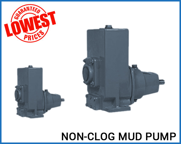
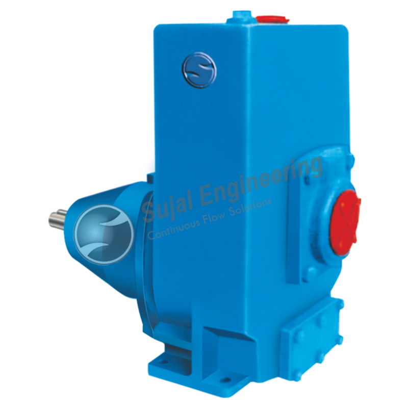
The 2,200-hp mud pump for offshore applications is a single-acting reciprocating triplex mud pump designed for high fluid flow rates, even at low operating speeds, and with a long stroke design. These features reduce the number of load reversals in critical components and increase the life of fluid end parts.
The pump’s critical components are strategically placed to make maintenance and inspection far easier and safer. The two-piece, quick-release piston rod lets you remove the piston without disturbing the liner, minimizing downtime when you’re replacing fluid parts.
The operation of formation testers may be more readily understood with reference to the structure of a conventional wireline formation tester shown in FIGS. 1A and 1B. As shown in FIG. 1A, the wireline tester 100 is lowered from an oil rig 2 into an open wellbore 3 filled with a fluid commonly referred to in the industry as “mud.” The wellbore is lined with a mudcake 4 deposited onto the wall of the wellbore during drilling operations. The wellbore penetrates a formation 5.
During this type of test operation for a wireline-conveyed tool, pressure data collected downhole is typically communicated to the surface electronically via the wireline communication system. At the surface, an operator typically monitors the pressure in flowline 119 at a console and the wireline logging system records the pressure data in real time. Data recorded during the drawdown and buildup cycles of the test may be analyzed either at the well site computer in real time or later at a data processing center to determine crucial formation parameters, such as formation fluid pressure, the mud overbalance pressure, i.e. the difference between the wellbore pressure and the formation pressure, and the mobility of the formation.
Despite the advances made in developing methods for performing pretests, there remains a need to eliminate delays and errors in the pretest process, and to improve the accuracy of the parameters derived from such tests. Because formation testing operations are used throughout drilling operations, the duration of the test and the absence of real-time communication with the tools are major constraints that must be considered. The problems associated with real-time communication for these operations are largely due to the current limitations of the telemetry typically used during drilling operations, such as mud-pulse telemetry. Limitations, such as uplink and downlink telemetry data rates for most logging while drilling (LWD) or measurement while drilling (MWD) tools, result in slow exchanges of information between the downhole tool and the surface. For example, a simple process of sending a pretest pressure trace to the surface, followed by an engineer sending a command downhole to retract the probe based on the data transmitted may result in substantial delays which tend to adversely impact drilling operations.
Formation pressure while drilling (FPWD) measurements, wherein a two phase test protocol is implemented, illustrates the need for real-time formation testing data communication. For example, a FPWD pretest may comprise a first phase, perhaps including drawdown and buildup cycles, conducted as an investigation phase and a second phase, perhaps again including drawdown and buildup cycles, conducted as a measurement phase. Data from the investigation phase may used to configure/perform the measurement phase. If the data from the investigation phase is not provided uphole, appropriate analysis and/or control with respect to configuring the measurement phase, continuing the test, etc. may not be possible. Similarly, if data from the measurement phase is not provided uphole, appropriate analysis and/or control with respect to continued drilling operations, further testing, etc. may not be possible. A 5 minute time-limited pretest having a 15 Hz sampling rate with 16 bits/sample, for example, produces 72000 bits per data channel. However, where mud pulse telemetry is implemented, the communication channel capacity is typically limited to between 0.5 to 12 bits/sec. Such a communication channel is typically insufficient to carry the aforementioned FPWD pretest data in real-time.
FIGS. 16A-C show flow chart detailing the steps involved in performing the mud filtration phase of the flow chart of FIG. 13, wherein FIG. 16A shows a mud filtration phase, FIG. 16B shows a modified mud filtration phase with a repeat compression cycle, and FIG. 16C shows a modified mud filtration phase with a decompression cycle;
FIG. 21 shows a fluid compressibility correction chart which may be used to provide corrected mud compressibility when the original mud compressibility is performed at a different temperature and/or pressure;
In another example, with equalizing valve 128 aopen mud may be withdrawn from the wellbore into the tool by means of pretest piston 118 a. On closing equalizing valve 128 a,probe isolation valve 121 aand sample line isolation valve 124 afluid may be trapped within the tool between these valves and the pretest piston 118 a. Pressure gauge 130 amay be used to monitor the wellbore fluid pressure continuously throughout the operation of the tool and together with pressure gauges 120 aand/or 123 amay be used to measure directly the pressure drop across the mudcake and to monitor the transmission of wellbore disturbances across the mudcake for later use in correcting the measured sandface pressure for these disturbances.
Other techniques may be used to determine deviation point 34. For example, another technique for determining the deviation point 34 is based on mud compressibility and will be discussed further with respect to FIGS. 9-11.
where nPis a number with a value equal to or greater than, for example, 4, typically 10 or greater, δPis the nominal resolution of the pressure measuring instrument; and εPis a small multiple, say 2, of the pressure instrument noise—a quantity which may be determined prior to setting the tool, such as during the mud compressibility experiment.
As shown in FIG. 7, the termination point 350 depicts the end of the investigation phase 13 following completion of the build up phase 340. However, there may be instances where it is necessary or desirable to terminate the pretest. For example, problems in the process, such as when the probe is plugged, the test is dry or the formation mobility is so low that the test is essentially dry, the mud pressure exactly balances the formation pressure, a false breach is detected, very low permeability formations are tested, a change in the compressibility of the flowline fluid is detected or other issues occur, may justify termination of the pretest prior to completion of the entire cycle.
Referring now to FIG. 10, an alternate embodiment of the foregoing method for estimating formation properties incorporating a mud compressibility phase 11 is depicted. This embodiment comprises a mud compressibility phase 11, an investigation phase 13 and a measurement phase 14. Estimations of mud compressibility may be used to refine the investigation phase procedure leading to better estimates of parameters from the investigation phase 13 and the measurement phase 14. FIG. 11A depicts a pressure trace corresponding to the method of FIG. 10, and FIG. 11B shows a related graphical representation of the rate of change of the pretest chamber volume.
The mud compressibility measurement may be performed, for example, by first drawing a volume of mud into the tool from the wellbore through the equalizing valve 128 aby means of the pretest piston 118 a, isolating a volume of mud in the flowline by closing the equalizing valve 128 aand the isolation valves 121 aand 124 a, compressing and/or expanding the volume of the trapped mud by adjusting the volume of the pretest chamber 114 aby means of the pretest piston 118 aand simultaneously recording the pressure and volume of the trapped fluid by means of the pressure gauge 120 a.
FIGS. 11A and 12 depict the mud compressibility phase 11 in greater detail. The mud compressibility phase 11 is performed prior to setting the tool and therefore prior to conducting the investigation and measurement phases. In particular, the tool does not have to be set against the wellbore, nor does it have to be immobile in the wellbore in order to conduct the mud compressibility test thereby reducing the risk of sticking the tool due to an immobilized drill string. It would be preferable, however, to sample the wellbore fluid at a point close to the point of the test.
The steps used to perform the compressibility phase 11 are shown in greater detail in FIG. 12. These steps also correspond to points along the pressure trace of FIG. 11A. As set forth in FIG. 12, the steps of the mud compressibility test include starting the mud compressibility test 510, drawing mud from the wellbore into the tool 511, isolating the mud volume in the flow line 512, compressing the mud volume 520 and terminating the compression 530. Next, the expansion of mud volume is started 540, the mud volume expands 550 for a period of time until terminated 560. Open communication of the flowline to wellbore is begun 561, and pressure is equalized in the flowline to wellbore pressure 570 until terminated 575. The pretest piston recycling may now begin 580. Mud is expelled from the flowline into the wellbore 581 and the pretest piston is recycled 582. When it is desired to perform the investigation phase, the tool may then be set 610 and open communication of the flowline with the wellbore terminated 620.
Mud compressibility relates to the compressibility of the flowline fluid, which typically is whole drilling mud. Knowledge of the mud compressibility may be used to better determine the slope of the line 32 (as previously described with respect to FIG. 7), which in turn leads to an improved determination of the point of deviation 34 signaling flow from the formation. Knowledge of the value of mud compressibility, therefore, results in a more efficient investigation phase 13 and provides an additional avenue to further refine the estimates derived from the investigation phase 13 and ultimately to improve those derived from the measurement phase 14.
Mud compressibility Cmmay be determined by analyzing the pressure trace of FIG. 11A and the pressure and volume data correspondingly generated. In particular, mud compressibility may be determined from, the following equation:
where Cmis the mud compressibility (1/psi), V is the total volume of the trapped mud (cm3), p is the measured flowline pressure (psi), {dot over (p)} is the time rate of change of the measured flowline pressure (psi/sec), and qprepresents the pretest piston rate (cm3/sec).
To obtain an accurate estimate of the mud compressibility, it is desirable that more than several data points be collected to define each leg of the pressure-volume trend during the mud compressibility measurement. In using equation (16) to determine the mud compressibility the usual assumptions have been made, in particular, the compressibility is constant and the incremental pretest volume used in the measurement is small compared to the total volume V of mud trapped in the flowline.
The utility of measuring the mud compressibility in obtaining a more precise deviation point 34 ais now explained. The method begins by fitting the initial portion of the drawdown data of the investigation phase 13 to a line 32 aof known slope to the data. The slope of line 32 ais fixed by the previously determined mud compressibility, flowline volume, and the pretest piston drawdown rate. Because the drawdown is operated at a fixed and precisely controlled rate and the compressibility of the flowline fluid is a known constant that has been determined by the above-described experiment, the equation describing this line with a known slope a is given by:
where V(0) is the flowline volume at the beginning of the expansion, Cmis the mud compressibility, qpis the piston decompression rate, p+ is the apparent pressure at the initiation of the expansion process. It is assumed that V(0) is very much larger than the increase in volume due to the expansion of the pretest chamber.
A stretch of data points that fall on a line having the defined slope a, to within a given precision, is identified. This line represents the true mud expansion drawdown pressure trend. One skilled in the art would appreciate that in fitting the data points to a line, it is unnecessary that all points fall precisely on the line. Instead, it is sufficient that the data points fit to a line within a precision limit, which is selected based on the tool characteristics and operation parameters. With this approach, one can avoid the


 8613371530291