
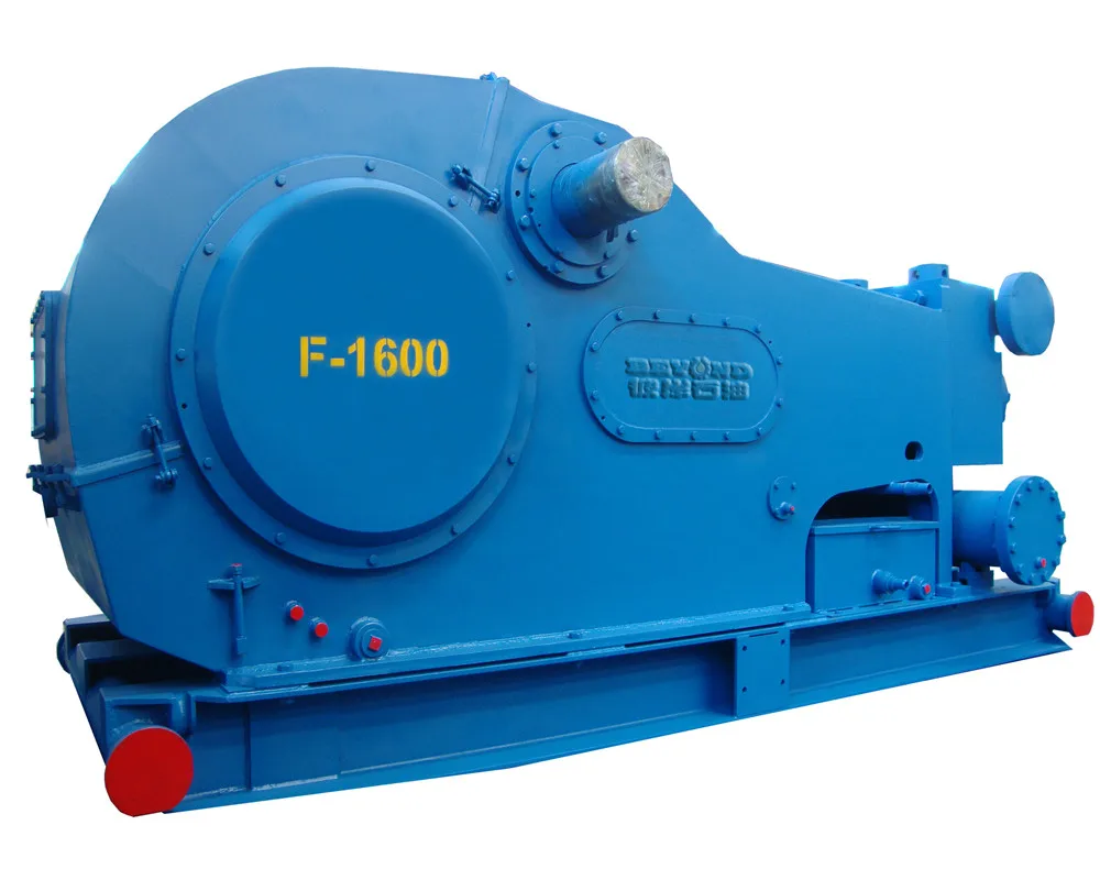
f 1600 triplex mud pump pricelist

This website is using a security service to protect itself from online attacks. The action you just performed triggered the security solution. There are several actions that could trigger this block including submitting a certain word or phrase, a SQL command or malformed data.

Choose a used Emsco FB-1600 Triplex Mud Pump from our inventory selection and save yourself some money on your next shallow drilling oilfield project. This Emsco FB-1600 Triplex Mud Pump is used and may show some minor wear.
We offer wholesale pricing on new Emsco FB-1600 Triplex Mud Pump and pass the savings on to you. Contact us to compare prices of different brands of Mud Pump. This equipment is brand new and has never been used.
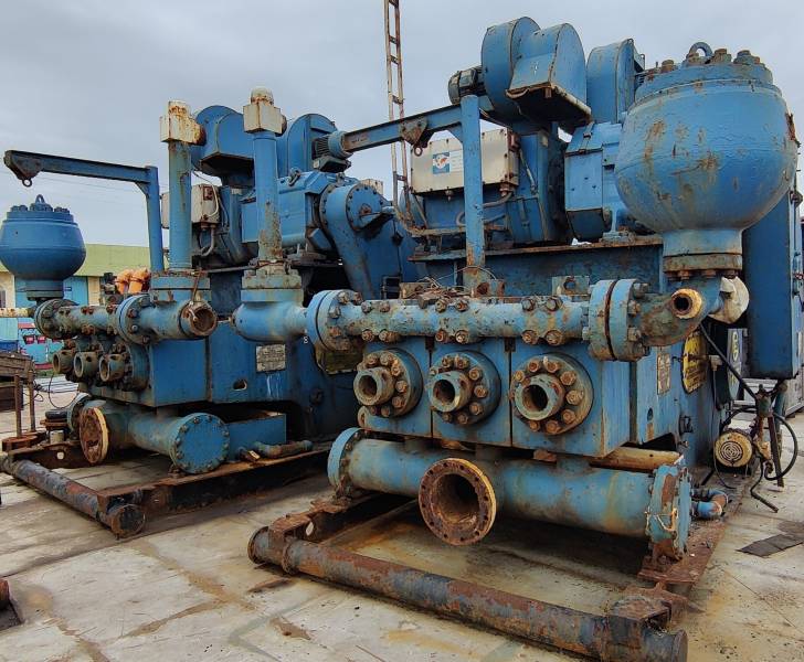
Our large network often has surplus Emsco FB-1600 Triplex Mud Pump that go unused from a surplus purchase or a project that was not completed. Contact us to see what Emsco FB-1600 Triplex Mud Pump we have in inventory. The surplus Emsco FB-1600 Triplex Mud Pump are considered new but may have some weathering depending on where it was stored. Surplus oilfield equipment is usually stored at a yard or warehouse.
We have refurbished Mud Pumpthat have been used and brought up to functional standards. It is considered a ready to use, working Mud Pump. Please contact us for more information about our refurbished Emsco FB-1600 Triplex Mud Pump. These Mud Pump have been used and brought up to functional standards. It is considered a working Mud Pump. Please contact us for more information about the product.

New: A brand-new, unused, unopened, undamaged item in its original packaging (where packaging is applicable). Packaging should be the same as what is found in a retail store, unless the item was packaged by the manufacturer in non-retail packaging, such as an unprinted box or plastic bag. See the seller"s listing for full details.See all condition definitionsopens in a new window or tab

A wide variety of mud pumps f 1600 options are available to you, such as 1 year, not available and 2 years.You can also choose from new, used mud pumps f 1600,as well as from energy & mining, construction works , and machinery repair shops mud pumps f 1600, and whether mud pumps f 1600 is 1.5 years, 6 months, or unavailable.
The NOV triplex pumps have three cylinders with single acting. The pistons are moved back and pull in drilling mud through open intake valves. When the pistons are moved forward and the drilling fluid is pushed out through open discharge valves.
NOV Emsco FB-1600 Triplex Mud Pumps have many advantages they weight 30% less than a duplex of equal horsepower or kilowatts. The lighter weight parts are easier to handle and therefore easier to maintain. The other advantages include;
One of the more important advantages of triplex over duplex pumps, is that they can move large volumes of mud at the higher pressure is required for modern deep hole drilling.
NOV Emsco FB-1600 Triplex Mud Pump are gradually phasing out duplex units. In a triplex pump, the pistons discharge mud only when they move forward in the liner. Then, when they moved back they draw in mud on the same side of the piston. Because of this, they are also called “single acting.” Single acting triplex pumps, pump mud at a relatively high speeds. NOV Emsco FB-1600 Triplex Mud Pump has three pistons each moving in its own liner. It also has three intake valves and three discharge valves. It also has a pulsation dampener in the discharge line.
triplex mud pumps and triplex mud pump parts meet the industry standards established by the American Petroleum Institute (API). As a global supplier of quality oilfield equipment to the oil and gas industry, we ship our products around the world.
Besides triplex mud pumps and triplex mud pump parts, we supply drilling rigs, workover rigs, top drives, drilling equipment, blowout preventers, BOP control systems, choke and kill manifolds, well service pumps for well cementing and hydraulic fracturing, wellhead equipment, casing heads, tubing heads, X-mas trees, FC type gate valves, etc. Please visit our company website
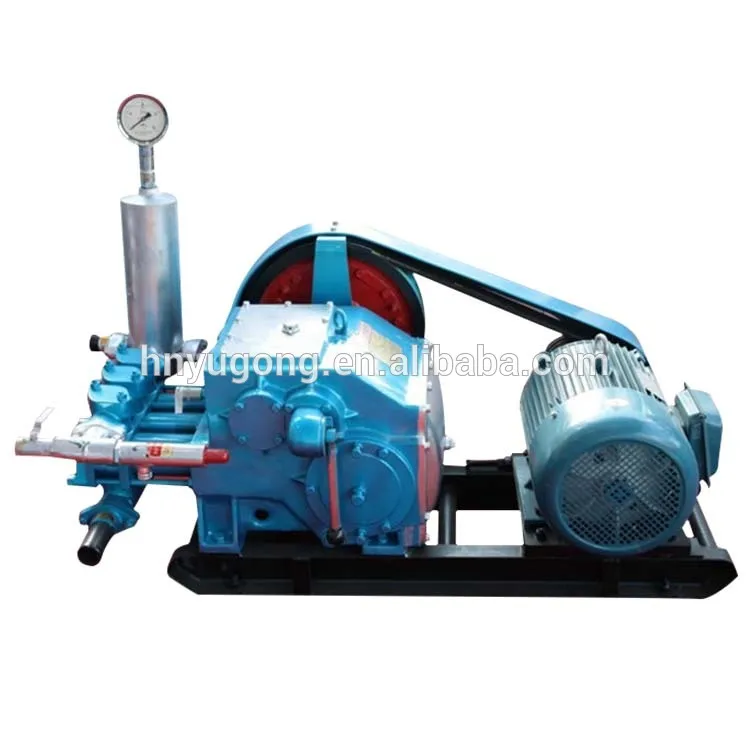
We supply unitized mud pump packages driven by DC or AC electric motors or diesel engines for electric and mechanical drilling rigs. The client can select DC or AC motors and diesel engine brands such as Caterpillar, Detroit, Cummins or others. Our unitized mud pump packages including everything on the skid and usually they are ready to work at delivery.
Xi"an Kingwell Oilfield Machinery Co.,Ltd is a professional supplier for oilfield products according to the API standard. Our products have exported to USA, Canada, Australia, Egypt, India and Uae, etc with high quality and short supply and good service, our products have got good reputation home and abroad .
Equipped with latest machining facilities. Our company could meet long term production target and be governed efficiently by well-qualified and experienced Board of Directors and Engineers.
We have a team of well qualified and experienced field support personnel for Training. According to customer"s requirements, we provide operation training service for our customers who cooperated with us.
We believe in Customer delight, achieved by the supply of Quality Products & Services and Continual Improvement in our Manufacturing Processes for timely delivery at competitive prices. We work in a professional, competitive, and cost-effective manner consistent with the Customer requirement
Any interest of above products or relative parts, PLS feel free contact back, and we will offer a good price and show you our best service upon received from you.

This website is using a security service to protect itself from online attacks. The action you just performed triggered the security solution. There are several actions that could trigger this block including submitting a certain word or phrase, a SQL command or malformed data.

14 P-220 Mud Pumps 3 available completely overhauled. The pumps have been machine inspected and all data will be provided. These 2200 HP pumps complete with Southwest fluid end modules which have been reworked and pressure tested by Southwest and P-QUIP liner retention systems. The drives can be set up for AC or DC power. All Master Rig equipment meets or exceeds O.E.M. standards and a complete data pack is furnished with purchase. Please call if you have any questions.
READY TO SHIP - Three (3) completely refurbished 1600 HP Continental Emsco 7500 PSI Mud Pump Packages - liner spray system, suction manifold and dampener, discharge strainer cross, reset relief valve, 20 gallon pulsation dampener, 75 HP charge pump, two (2) GE 752 1000 HP rear mounted motors, 10 HP blower, mounted on a 3 runner skid with loading hitches and much more. Units come with complete data books and have been tested. MRI is a API facility and units comply with API standards.
Duplex mud pump package completely refurbished and never operated. Tri-Services Manufacturing TSM-500 pump, CAT engine. Data book provided with complete refurbishment details.

National Oilwell Varco References: SO Number / Project Number: 188074 Document Number: D2G1008930-FDD-001 Revision: 01 Volume: 1 of 1
www.nov.com Document Number: D2G1008930-FDD-001 Revision: 01 Page: ii
01 8/11/2014 For Information T. Schutt J. Olson B. Schumer Rev Date (dd/mm/yyyy) Reason for Issue Prepared Checked Approved
www.nov.com Document Number: D2G1008930-FDD-001 TOCTABLE OF CONTENTS Revision: 01 Page: 1
www.nov.com Document Number: D2G1008930-FDD-001 TOC 1TABLE OF CONTENTS Revision: 01 Page: 1
www.nov.com Document Number: D2G1008930-FDD-001 TOC 2TABLE OF CONTENTS Revision: 01 Page: 1
www.nov.com Document Number: D2G1008930-FDD-001 TOC 2.1TABLE OF CONTENTS Revision: 01 Page: 1
Technical Specification Pre-Shipment And Storage PS-4030 02 Preservation For New-Build NOV Triplex Mud Pumps
Product Information Bulletin Triplex Mud Pumps Power 01-05-01-MP 06 End Lubrication Oil Additive and wear-in Period
Procedure The Use of and Application of Safety Wire for ASP00019 A Secondary Retention Design Specification Design Torque Standard DS00008 F General Lubrication Bulletin General Lubrication Bulletin CE-538E 06 for CE Drilling Equipment
RIG/PLANT REFERENCE REFERENCE DESCRIPTION Triplex Mud PumpADDITIONAL CODE SDRL CODE TOTAL PGS This document contains proprietary and confidential information National Oilwell Varco which belongs to National-Oilwell Varco, L.P., its affiliates orREMARKS subsidiaries (all collectively referred to hereinafter as "NOV"). It is loaned for limited purposes only and remains the property of NOV. 11000 Corporate Centre Drive Reproduction, in whole or in part, or use of this design or Suite 200MAIN TAG NUMBER DISCIPLINE distribution of this information to others is not permitted without the Houston, Texas 77041 express written consent of NOV. This document is to be returned to NOV upon request and in any event upon completion of the use for U.S.A.CLIENT PO NUMBER which it was loaned. This document and the information contained and represented herein is the copyrighted property of NOV. Phone: +1-281-854-0400 National Oilwell Varco Fax: +1-281-854-0607CLIENT DOCUMENT NUMBER DOCUMENT NUMBER REV
02 12.09.2012 For Information RLP BTS GDH 1 15.08.2006 For Information GDH GDH GDH 0 07.05.1990 For Information GDH GDH GDH Rev Date (dd.mm.yyyy) Reason for issue Prepared Checked Approved
Revision Change Description 0 Initial Release 1 Updated Entire Document 02 Added NOV Standard Front Cover & Updated Page Formats
1 SCOPE.............................................................................................................................. 42 MANUFACTURING PLANT PRESERVATION PRIOR TO PAINT .................................. 43 MANUFACTURING PLANT PRESERVATION AFTER PAINT ........................................ 54 STORAGE AT MANUFACTURING PLANT OR FINAL DESTINATION .......................... 65 STORAGE PREPARATIONS FOR MAIN DRIVE MOTORS. ........................................... 66 PRESERVATION PROCEDURE WHEN STORAGE EXCEEDS SIX (6) MONTHS OFINITIAL PRESERVATION. .......................................................................................................... 67 START-UP AFTER STORAGE ........................................................................................ 78 CONTACT DETAILS FOR NOTED CORROSION PREVENTATIVE MATERIALS ......... 79 EXHIBIT 1 ......................................................................................................................... 810 EXHIBIT 2 ......................................................................................................................... 9
This specification covers the preservation and storage procedure for shipment of new-build NOV Triplex Mud Pumps shipped from the manufacturing plant.
This specification is intended to provide preservation of new-build NOV Triplex Mud Pumps for six (6) months from the shipment of the mud pump from the manufacturing facility. If a pump is to be stored for a period of time exceeding six (6) months, additional precautions should be taken as outlined in this specification.
National Oilwell Varco recommends that all pumps are inspected for any signs of corrosion and for proper preservation at a minimum every three (3) months for pumps stored outside and every six (6) months for pumps stored indoors.
Drain all water and clean out liner wash tank. Remove drain plug in bottom of liner wash pump and drain water then reinstall plug. Remove discharge flange from liner wash pump and pour one (1) pint of inhibiting oil-based concentrate (Cortec VpCI 329 Vapor Corrosion Inhibiting oil-based concentrate or equivalent) into liner wash pump. Rotate two (2) revolutions by hand to distribute the product. Re-install discharge flange.
Drain all oil from pump power end sump and remove crosshead covers and inspection covers. Clean out oil sump as per National Oilwell PS-3081 (Mud Pump Cleanliness). Spray all internal machined parts of power end and crosshead area with inhibiting oil-based concentrate (Cortec VpCI 329 Vapor Corrosion Inhibiting oil-based concentrate or equivalent). Rotate pump turn and re-spray. Pour quantity of inhibiting oil-based concentrate specified in the table below into power end sump.
Mud Pump Models Quantity of Inhibitor 14P, FC 2200 5 Gallons 12P, 10P, HD or A1700/1400PT, FB/FC/FD 1600, FB 1300 3 Gallons 9P, 8P, B or A850-1100PT, F/FD 1000, F 800 2 Gallons 7P, A600PT, FD 500 1 Gallon
For pumps equipped with chain drives, spray internal machined parts inside chain cases with inhibiting oil-based concentrate (Cortec VpCI 329 Vapor Corrosion Inhibiting oil based concentrate or equivalent).
Remove fluid end valve covers, seals, valves springs and seats and treat internal cavities of fluid ends, discharge manifold, discharge strainer block and suction manifold with rust preventative (CRC SP400 or equivalent). Coat threads with anti-seize (KOPR KOTE 10002 or equivalent) and coat bottom side of valve cover with rust preventative. Reinstall seals and fluid end valves covers hand tight. Customer liners, pistons, piston rods, valves, seats, springs and liner retention parts are not used for plant testing. These expendables are checked for preservation when packed and then shipped with the loose parts.
Remove breather and pack with loose parts for later shipment with pump. Seal breather hole with a greased solid plug. Affix a warning label near the breather opening (see Exhibit 1).
Seal all other pipe work (air, water, and electrical) with plastic caps of the correct size and style. Electrical J-boxes are to be encased in protective plastic wrap. Place two (2) one- pound bags of desiccant inside each J-box before sealing with tape. Wrap pressure gauges with bubble paper and plastic.
Spray all machined unpainted loose parts and expendables to be shipped with pump with rust preventative (CRC SP400 or equivalent). All parts will be wrapped or boxed to prevent damage.
Affix one (1) warning label (see Exhibit 2) to the power end pump cover and one (1) warning label on the fluid end assembly of the pump. Affix warning labels on each loose part container. In cases where the equipment will be boxed at an offsite export packer, a sufficient number of warning labels will be supplied with the shipment.
Indoor storage is preferred whenever possible; but if outside storage is required, ensure pump is stored away from salt water spray, sand blast or other adverse conditions. It is highly recommended that ship loose parts be stored indoors to eliminate conditions that promote condensation and direct sources of moisture.
For storage preparations for main drive motors, National Oilwell Varco recommends that the original manufacturers instructions be followed. If space heaters are supplied, the J- box plastic wrap must be removed and the heaters should be connected throughout the complete storage period.
Note: It is recommended that inspections be carried out on six (6) month cycles when pumps are in indoors and three (3) month cycles when stored outside.
Any pump that has been in storage will need a thorough inspection prior to start-up to insure it has not been damaged in any way and that all parts are properly in place. Failure to observe the following points can result in serious damage. Before servicing the pump, the power end sump and chain drives housings will need to be drained of any inhibiting additive. The Cortec brand products used for preservation are compatible with all lubricating oils and need not be totally removed when putting equipment into service.
To service the Power End after storage and prior to start-up, remove all covers and thoroughly clean and inspect all of the parts and finished surfaces. Check all of the bearings to make certain they are clean and in good condition. Fill the power end with clean EP oil of the proper viscosity to the proper level. Make sure oil is poured into the oil distribution trough and is worked into all of the bearings. Replace all covers and install breather.
To service the Fluid End after storage and prior to start-up, remove covers and thoroughly clean and inspect inside of the fluid end cylinders. Properly install valves, pistons, liners and all other fluid end parts. Carefully tighten all bolts, nuts, studs and working connections to specified torque requirements.
Product Name Company Contact Number Cortec VpCI 329 Gulf Corrosion Control (713)681-7500 CRC Industries Inc. SP400 Fastenal (713)983-7715 KOPR-KOTE Drago Supply Co. (800)553-2363
www.nov.com DOCUMENT OR DRAWING NO. PAGE 1 of ENGINEERING EDN-1688 12SUBJECT COMMISSIONING PROCEDURE, FB/FD-1600 APPROVED REVISED DATE REV.
TRIPLEX MUD PUMP GDH 02PREPARED BY DATE CHECKED BY DATE
DOCUMENT TITLE: Commissioning Procedure, FB/FD-1600 Triplex Mud Pump DOCUMENT OR DRAWING NO. PAGE 2 of ENGINEERING EDN-1688 12SUBJECT COMMISSIONING PROCEDURE, FB/FD-1600 APPROVED REVISED DATE REV.
TRIPLEX MUD PUMP GDH 02PREPARED BY DATE CHECKED BY DATE
1. Power End.................................................................................................. 3 2. Main Electric Drive Motors 3 3. Auxiliary A/C Motors. 4 4. Instrumentation........................................................................................... 4 5. Liner Wash System..................................................................................... 4 6. Fluid End.................................................................................................... 4 7. Suction Dampener/Desurger....................................................................... 4 8. Pulsation Dampener.................................................................................... 4 9. Pressure Gauge............................................................................................ 5 10. Reset Relief Valve....................................................................................... 5 11. Discharge Strainer 5 12. Mud Pump Drive Assembly. 5 a. Belt Drive Units 5 b. Chain Drive Units. 5
1. Pre-Commission Checks.. 6 2. Commissioning Operational Test. 8 3. Inspections/Check-Offs during Test Program.. 9 DOCUMENT OR DRAWING NO. PAGE 3 of ENGINEERING EDN-1688 12SUBJECT COMMISSIONING PROCEDURE, FB/FD-1600 APPROVED REVISED DATE REV.
TRIPLEX MUD PUMP GDH 02PREPARED BY DATE CHECKED BY DATE
The initial startup procedures are written to assist the operator in preparing the pump packages for normaloperation. The startup procedures are separated into two categories: Part I: Pre-Commissioning, and PartII: Commissioning Procedures. It is suggested that a copy of these pages be made for each pump to beused as a check-off sheet.
a. Drain and flush any moisture or contamination that has accumulated in the power end reservoir. Fill to the FULL mark on the dipstick with the recommended oil.
Ambient Temperature: 0F to 85F (-18C to 33C) = AGMA No. 4 EP 30F to 155F (-1C to 68C) = AGMA No. 6 EP
Note: The rust preventative on the internal surfaces of the pump is oil-soluble and is compatible with the lubricants recommended above. It is not necessary to flush and drain unless the preservative has become contaminated (water, sand etc.).
Megger test the motors. Check each motor separately for the correct rotation. Reconnect if necessary. Megger test the blower motors. Check blower motors for correct rotation and quantity of air flow. DOCUMENT OR DRAWING NO. PAGE 4 of ENGINEERING EDN-1688 12SUBJECT COMMISSIONING PROCEDURE, FB/FD-1600 APPROVED REVISED DATE REV.
TRIPLEX MUD PUMP GDH 02PREPARED BY DATE CHECKED BY DATE
Check to assure that all instrumentation has been properly hooked up. Check the calibration test sheets for validity and recalibrate if necessary.
Clean liner wash tank, if needed, and fill with fresh clean water. Ensure that supply hoses and spray nipples are installed correctly. Start pump and adjust regulating valve to maximum flow without splash onto the extension rods.
Check to assure that all liners, valves, and pistons are installed properly in accordance with the installation instructions. Ensure that the liner end covers are installed on the rear end of the liners. Ensure that the baffle discs are installed on the end of the crosshead extension rods. Clean grease and paint from the exposed parts of the extension rods, checking for burrs. Coat rods with a light oil.
NOTE: When charging the bladder, make sure that the mud pump suction line valve has been closed and that all pressure has been bled off of the suction manifold surrounding the suction desurger
If a dampener is used, charge dampener with a hand-operated air pump to 10 PSI (0.7 bar). Once pump operations have been started, check the operation of the suction dampener by inspecting the sight glass. Add or release air pressure through the Shraeder valve to keep the diaphragm between the midpoint and the bottom of the sight glass.
Refer to manufacturers instructions for charging the dampener. USE ONLY NITROGEN OR AIR! DO NOT USE OXYGEN. DOCUMENT OR DRAWING NO. PAGE 5 of ENGINEERING EDN-1688 12SUBJECT COMMISSIONING PROCEDURE, FB/FD-1600 APPROVED REVISED DATE REV.
TRIPLEX MUD PUMP GDH 02PREPARED BY DATE CHECKED BY DATE
Check the installation and the setting. NO SHUT-OFF VALVE is to be between the pump discharge and the relief valve. Ensure that piping from the discharge port goes directly to the mud tank/pit and is securely tied down, with a minimum downward slope of 1/4 per foot. Ensure that piping has pressure rating equal to the relief valve highest setting.
Remove the strainer screen from the housing and assure that it is clean and free from obstructions. Check the stud nuts for proper make-up torque.
Check the belt guards to ensure that belts will not drag on the guard. Check the belt tension as instructed in the maintenance section of the operations manual. Check the alignment of the drive motors.
Check the chain guards to ensure that the chains will not drag on the guard. Check the oil pump to ensure that the relief valve is installed on the suction side. Start the pump and ensure that the spray nozzles are spraying oil over the full width of the chain. Adjust the relief valve to 15-25 PSI output with the warm oil. DOCUMENT OR DRAWING NO. PAGE 6 of ENGINEERING EDN-1688 12SUBJECT COMMISSIONING PROCEDURE, FB/FD-1600 APPROVED REVISED DATE REV.
TRIPLEX MUD PUMP GDH 02PREPARED BY DATE CHECKED BY DATE
The power end and the fluid end have gone through rigorous tests prior to being shipped from the manufacturing site; therefore, the following recommendations for the commissioning test are made for the purpose of checking the overall unitization functions, including instrumentation, and to assure that there are no problems which may have occurred during transportation and storage.
Operation of the pump in parallel to check the SCR-Motor assignments and controls, volumetric displacement and mudline systems are at the option of the purchaser.
Check the discharge mudline to assure that all necessary valves are open. Ensure that the mud tanks are full of test fluid (mud/water) prior to startup.
Make the desired assignment of the SCR-Motor Control System to the pump motors, and open the throttle slightly. Check to ensure that charge pump and liner wash motors have started.
If no immediate problems are encountered, slowly throttle the pump to approximately 60 SPM and continue operating the mud pump while making the following inspections to assure that all systems are working properly:
Adjust the regulator valve for proper volume of cooling fluid. 10 US Gallons (38 Liter) per minute per liner. Check the coolant temperature. 150F (66C) maximum.
4) Check for interference or dragging in the belt/chain drive assemblies. DOCUMENT OR DRAWING NO. PAGE 7 of ENGINEERING EDN-1688 12SUBJECT COMMISSIONING PROCEDURE, FB/FD-1600 APPROVED REVISED DATE REV.
TRIPLEX MUD PUMP GDH 02PREPARED BY DATE CHECKED BY DATE
Pump A/C motor operating properly. Valves open for the proper volume of drilling fluid. Gauges/controls functioning properly.
Check the valve for proper relief setting. The valve should be set 10% above the pressure rating for the liner size being used. Refer to the nameplates on each side of the pump or the pump datasheet to obtain the operating pressure for that particular size liner. DOCUMENT OR DRAWING NO. PAGE 8 of ENGINEERING EDN-1688 12SUBJECT COMMISSIONING PROCEDURE, FB/FD-1600 APPROVED REVISED DATE REV.
TRIPLEX MUD PUMP GDH 02PREPARED BY DATE CHECKED BY DATE
The following are basic guidelines for conducting of an eight (8) hour operational test. The pump was test run under pressure in the manufacturing plant but with different motors and drives.
RATED LINER PRESSURE*...180 min. @ 100 SPM _______ _______ * Not to exceed pressure rating of fluid end. DOCUMENT OR DRAWING NO. PAGE 9 of ENGINEERING EDN-1688 12SUBJECT COMMISSIONING PROCEDURE, FB/FD-1600 APPROVED REVISED DATE REV.
TRIPLEX MUD PUMP GDH 02PREPARED BY DATE CHECKED BY DATE
The overall performance of the unitized pump package should be continuously monitored during the eight hour test program. The following checks should be made and recorded each two hours of operation.
LOAD SHARE (YES/NO).. ______ _____ _____ _____ _____ DOCUMENT OR DRAWING NO. PAGE 10 of ENGINEERING EDN-1688 12SUBJECT COMMISSIONING PROCEDURE, FB/FD-1600 APPROVED REVISED DATE REV.
TRIPLEX MUD PUMP GDH 02PREPARED BY DATE CHECKED BY DATE
SUCTION MANIFOLD PRESS. ______ _____ _____ _____ _____ DOCUMENT OR DRAWING NO. PAGE 11 of ENGINEERING EDN-1688 12SUBJECT COMMISSIONING PROCEDURE, FB/FD-1600 APPROVED REVISED DATE REV.
TRIPLEX MUD PUMP GDH 02PREPARED BY DATE CHECKED BY DATE
_____________________________________________________________________________________ DOCUMENT OR DRAWING NO. PAGE 12 of ENGINEERING EDN-1688 12SUBJECT COMMISSIONING PROCEDURE, FB/FD-1600 APPROVED REVISED DATE REV.
TRIPLEX MUD PUMP GDH 02PREPARED BY DATE CHECKED BY DATE
Triplex Mud Pump For Models: FD-500, FD-800, FD-1000 & FD-1600
RIG/PLANT REFERENCE REFERENCE DESCRIPTION Triplex Mud PumpADDITIONAL CODE SDRL CODE TOTAL PGS This document contains proprietary and confidential information National Oilwell VarcoREMARKS which belongs to National Oilwell Varco; it is loaned for limited 1530 W Sam Houston Pkwy. N purposes only and remains the property of National Oilwell Varco. Reproduction, in whole or in part; or use of this design or Houston, TX 77043MAIN TAG NUMBER DISCIPLINE distribution of this information to others is not permitted without the Phone 713-935-8000 express written consent of National Oilwell Varco. This document is Fax 713-935-8382 to be returned to National Oilwell Varco upon request and in anyCLIENT PO NUMBER event upon completion of the use for which it was loaned. National Oilwell VarcoCLIENT DOCUMENT NUMBER DOCUMENT NUMBER REV
01 15.08.2006 New Manual TMH TMH KS Rev Date (dd.mm.yyyy) Reason for issue Prepared Checked Approved
This manual is provided for guidance of those who wish to install, repair, maintain, or adjust theNational Oilwell Varco equipment covered herein. This information has been prepared with abasic viewpoint to give accurate and concise data needed to perform minor adjustments as wellas major overhauls.
This information is not elementary, as it is intended for operators and servicemen who are familiarwith drilling equipment in general. It is not intended, nor would it be possible in such limitedspace, to cover every possible condition which may be encountered. Always use good, soundmechanical practices and safety precautions.
All specifications are in accordance with Engineering designs and should be adhered to in allrepairs. Operation and maintenance information on equipment other than National Oilwell Varcosis taken in part from the various manufacturers manuals. If the equipment manufacturers issuelater instructions, or in the event of conflict, the manufacturers information will take precedenceover that shown in this manual, unless specifically stated otherwise.
Refer to the General Lubrication Bulletin for approved lubricants. If any discrepancy existsbetween the recommendations in this manual and the General Lubrication Bulletin, those in theLubrication Bulletin will take precedence.
The manual sections follow logical divisions in major components, and cover all standardproduction unless otherwise specified. Specifications and components covered are for standardequipment current at the time this manual was approved for printing.
National Oilwell Varco reserves the right to discontinue models at any time, or changespecifications or design of any model without notice and without incurring any obligation.
IN ORDER TO PREVENT PERSONAL INJURY during performance of any maintenanceor inspection procedures, this equipment must be shut down and not operating. Eachmotor and generator is equipped with a motor cutout switch. This switch should be IN,and the safety bar in place, when any maintenance or inspection procedures areperformed. Employ good mechanical practices when making maintenance repairs,adjustments, inspections, etc.
When operating all mechanical and electrical equipment, all safety devices must beengaged, properly adjusted, and in good operating condition, including overtravel devicesfor traveling blocks, warning or shutdown devices for engines, etc.
PREFACE.................................................................................................................................... 31 INSTALLATION OF NEW PUMP ................................................................................... 112 SETTING THE PUMP ..................................................................................................... 11 2.1 Land Installations.................................................................................................. 113 SUCTION SYSTEM REQUIREMENTS........................................................................... 16 3.1 Caution ................................................................................................................. 164 PREPARATION OF POWER END ................................................................................. 17 4.1 Power End Lubrication.......................................................................................... 17 4.2 Installation of Crosshead Extension Rods and Diaphragm Stuffing Box Seals..... 185 PISTON AND LINER COOLING SYSTEM ..................................................................... 19 5.1 Stationary spray (View A, Fig. 6) .......................................................................... 20 5.2 Moving Nozzle ...................................................................................................... 206 ASSEMBLY OF FLUID END PARTS ............................................................................. 23 6.1 Valves and Seats.................................................................................................. 237 FD-500, FD-800 & FD-1000............................................................................................ 24 7.1 Liners.................................................................................................................... 25 7.2 Piston Rod ............................................................................................................ 25 7.3 Piston Rod Clamps ............................................................................................... 25 7.4 Liner Cage and Lower Valve Guide ...................................................................... 26 7.5 Cylinder head ....................................................................................................... 26 7.6 Discharge Valve Pot Covers ................................................................................. 268 FD-1600 .......................................................................................................................... 27 8.1 Liner...................................................................................................................... 28 8.2 Piston Rod ............................................................................................................ 28 8.3 Piston Rod Clamps ............................................................................................... 29 8.4 Lower Valve Guide and Cylinder Head................................................................. 29 8.5 Discharge Valve Pot Covers ................................................................................. 29 8.6 Discharge Manifold all models .............................................................................. 30
8.7 Suction Flange...................................................................................................... 30 8.8 Accessory Manifold............................................................................................... 309 LUBRICATION ............................................................................................................... 31 9.1 Minimum Operating Speeds ................................................................................. 32 9.2 Controlled Flow Splash System ............................................................................ 33 9.3 Total Pressure lubrication System ........................................................................ 3410 MAINTENANCE OF THE LUBRICATION SYSTEM ...................................................... 3611 MAINTENANCE.............................................................................................................. 38 11.1 Power End ............................................................................................................ 38 11.2 Roller Bearings ..................................................................................................... 39 11.3 Pinion Shaft Assembly.......................................................................................... 41 11.4 Crankshaft Assembly (Fig. 16) ............................................................................ 42 11.5 Installing Crankshaft Assembly in Frame.............................................................. 46 11.6 Installation of Crosshead Guides .......................................................................... 48 11.7 Installation of Crossheads .................................................................................... 49 11.8 Checking crosshead alignment............................................................................. 5112 FLUID END MAINTENANCE.......................................................................................... 51 12.1 Fluid Cylinder Blocks ............................................................................................ 52 12.2 Suction Manifold ................................................................................................... 53 12.3 Discharge Manifold ............................................................................................... 53 12.4 Cylinder Head Thread Ring .................................................................................. 54 12.5 Welding and Repairs ............................................................................................ 54 12.6 Welding Procedures ............................................................................................ 58 12.7 Repairs to Valve Pot Cover Bore .......................................................................... 59
FD-500 (mm) FD-800 ( mm ) FD-1000 ( mm ) FD-1600 ( mm ) A 3-11-3/8 (1203) 4-8-7/8 (1445) 4-10-5/8 (1489) 5-0-5/8 (1540) B --- --- --- -- ---- -- 5-7-13/16 (1722) C 3-2-15/16 (989) 3-4-1/2 (1029) 3-8-3/8 (1127) 4-0-1/8 (1222) D 3-11-3/16 (1198) --- -- ---- -- 4-8-1/16 (1424) E 12-1/16 (305) 12-7/16 ( 316 ) 13-3/4 ( 349 ) 13-3/16 ( 335 ) F 3-1 (939) --- -- ---- -- 4-3-3/4 (1315) G 3-8-1/2 (1197) 3-11-1/8 (1197) 4-5-1/2 (1359) 4-11-3/4 (1518) H 4-9 (1448) 5-1-3/4 (1568) 8-0 92438) 7-10 (2388) J 6-9-7/8 (2079) 7-11-3/8 (2423) 8-4-1/4 (2546) 8-11-7/8 (2740)** K --- --- 4-6-1/4 (1378) 4-6-7/8 (1394) 4-10-1/4 (1480) L (Dia.) 5.5 (139) 7.00 (177.8) 7.750 (196.85) 8.500 (215.90) (Keyway) 1-1/4 x 5/8 (31.7 x 15.8) 1-3/4 x 7/8 (44.45 x 22.225) 2 x 1 (50.8 x 25.4) 2 x 1 (50.8 x 25.4) M 3-11 (1193) 4-3-3/8 (1305) 4-9-3/8 (1457) 5-5-3/4 (1670) N 5-0-3/4 (1543) 5-5-1/4 (1657) 5-11-1/8 (1807) 6-10 (2083) P 4-3-3/8 (1305) 4-6 (1372) 5-1 (1549) 6-1-3/8 (1864) Q 12-0 (3658) 13-0 (3962) 13-6 (4115) 16 (4877) R 1-3-5/16 (389) 1-3-5/8 ( 397 ) 1-6-7/8 ( 479 ) 1-9-3/4 ( 553 ) S 10 (254) 10 ( 254 ) 12 ( 305 ) 12-1/4 ( 311 ) T --- --- 1-1 ( 330 ) 1-1 ( 330 ) 1-4-1/2 ( 419 ) U --- --- 2-0-1/2 ( 622 ) 1-2-3/8 ( 365 ) 1-1-3/4 ( 349 ) V 3-0-3/4 (933) 3-1-1/2 ( 953 ) 2-2-3/8 ( 670 ) 2-6-1/4 ( 768 ) W 9-3/4 (250) 10-3/4 ( 273 ) 10-3/4 ( 273 ) 12-9/16 ( 319 ) X 1-4-7/8 (422) --- -- ---- -- 1-7-1/4 ( 489 )
FD-500 FD-800 FD-1000 FD-1600 Max. Liner Size 6-3/4 (171.45 mm) 6-3/4 (171.45 mm) 6-3/4 (171.45 mm) 7-1/2 (190.5 mm) and stroke 7-1/2 (191 mm) 9 (228.6 mm) 10 (254 mm) 12 (304.8 mm) Nominal HP 500 HP 800 HP 1000 HP 1600 HP Rating @ 165 SPM @ 150 SPM @ 140 SPM @ 120 SPM Type Gear Herringbone Herringbone Herringbone Double Helical 4.31:1 4.31:1 4.31:1 4.31:1 Lubrication Pressure and Splash to all Moving Parts Valve Pots API No. 6 API No. 6 API No. 6 API No. 7 Approx. Wt. 18,657 (8,463 kg) 26,603 (12,067 kg) 33,770 (15,318 kg) 46,820 (21,238 kg) (Lbs.)
Your National Oilwell Varco pump has been completely assembled and test operated under pressure before being shipped to the field. Unless otherwise instructed, the lubrication is drained from the power end and the expendable parts are removed from the fluid end. Before putting the pump into service, the following precautions and operations must be performed or checked.
2 SETTING THE PUMP The skids under the National Oilwell Varco pumps are suitable for most any type of installation. It should be noted, however, that the box type construction of the power frame has high resistance to bending but relatively less resistance against twist. Therefore, the support under the pump must be level and adequate to support the weight and operating forces exerted by the pump.
2.1 Land Installations In land installations, a mat of 3 X 12 (76.20 mm x 304.8 mm) boards laid side crosswise to the pump skids for the entire length, or at a minimum, at the points indicated in Fig. 2, is usually sufficient. The boards should be a few feet wider than the width of the pump skid runners. Wet or marshy locations may require a more stable foundation.
Suitable means, such as National Oilwell Varco pump spacers as shown in Fig. 3, should be used to keep the pump anchored and the drive in alignment. National Oilwell Varco mud pump spacers provide 8-1/2 (215.9mm) adjustment. Any desired length may be obtained by lengthening the standard pipe spacer, which is made of 3 (76.20mm) extra strong pipe.
2.1.1 Permanent Installations On permanent installations such as barge, platform, structural base, or concrete slab, where pump skids are bolted down, it is essential that the skids be properly shimmed to prevent possibility of twisting or distorting the power frame. The pump skids must sit solid on all shim points with bolts loose.
On barge installations, the pump skids are generally bolted down to T-beams running parallel and in line with the pump skids. Install shims at points shown in Figs. 2 and 4 and observe caution of proper shimming to prevent twist or distortion.
The shims on all installations should extend the full width of the skid beam flanges and have a minimum length of 12 (305mm).
On installations where the power unit or electric motor is mounted integrally with the pump skids, the preferred installation would be to set the pump package on the T-beam skids and provide retention blocks rather than bolts to hold it in place. This will allow the pump to float and minimize the transfer of barge deck or platform distortion into the frame.
2.1.2 Installation of the Drive The drive between the mud pumps and the power source, whether V-belts or multi-width chains, should be installed with the greatest care to assure maximum operating life with minimum of unexpected or undesirable shutdowns due to drive failures.
When installing the drive sheave or sprocket, make sure all grease or rust preventative is removed from the shaft and the bore of the drive. Remove all burrs or rough spots from the shaft, key, and keyway. Fit key to the keyways in both the shaft and drive and install key into shaft keyway.
Coat pinion shaft with a light coating of anti-seize compound or light oil and install the drive sheave or sprocket hub. Tighten hub bolts as indicated below:
When a wrench or length of pipe is used to increase leverage in tightening draw-up bolts, it is imperative to adhere to the wrench torque values given in the chart below. This adherence is important, because in mounting the hub, the tightening force on the bolts is multiplied many times by the wedging action of the tapered surface. This action compresses the hub for a snug fit on the shaft. If the bolt tightening forces are extreme, bursting pressure is created in the hub of the mounted pulley; this pressure may cause the pulley to crack. The hub bolts should always be tightened alternately and progressively.
QD Wrench Torque Wrench Length Wrench Pull Hub Ft. Lb. Inches Lbs. FD-500 P 540 (62 meter kg) 30 (.76 meters) 180 (82 kg) FD-800 W 600 (83 meter kg) 36 (.90 meters) 200 (92.2 kg) FD-1000 W 600 (83 meter kg) 36 (.90 meters) 200 (92.2 kg) FD-1600 W 600 (83 meter kg) 36 (.90 meters) 200 (92.2 kg)
Before installing the V-belts, check sheave grooves for wear. Worn or rounded grooves will destroy V-belts rapidly. The side walls must be straight. Sheave grooves must be free of dirt, rust or other extrusions which could damage the V- belts.
The final alignment of the V-belt sheaves should be checked after the V-belts have been installed and adjusted to their operating tension. If the sides of the sheaves are of equal distance from the centerline of the groove, check alignment by stretching TWO strings (fish line or piano wire preferred) along one side of the two sheaves, one above and one below the centerline, and moving one of the sheaves until the strings touch four points on the side of the sheave rims. This will determine that the centerline of the drives are parallel and the faces of the sheaves are square.
Adjust the belt tension by moving the sheaves apart until all of the sag has just been eliminated from the tight side of the belt and some of the belts on the slack side. Then increase the centers approximately (13mm) for each 100 (2540 mm) center distance. Example: On 150 (3810 mm) center, move pump an additional (19.5 mm).
DO NOT OBTAIN BELT TENSION BY PICKING UP END OF PUMP AND ALLOWING BELTS TO TIGHTEN UNDER WEIGHT OF PUMP AS END IS BEING LOWERED TO THE GROUND.
Proper installation and maintenance of the sprocket and chain drives are essential if good service life is to be obtained. Since many factors, such as chain width, center distances, speeds, and loads must be considered when determining the allowable tolerance for sprocket alignment, no good rule of thumb can be applied. The chain alignment must simply be held as nearly perfect as possible. A more precise alignment can be made by stretching two steel wires (piano wire) along one face of the two sprockets, one above and one below the centerline, and moving one of the sprockets until the wires touch at four points. This will determine that the centerlines of the drives are parallel and the faces of the sprockets are square.
The pump drive chain lubrication system on the majority of National Oilwell Varco pumps is an independent system having its own oil pump, reservoir, and drive. Fill chain case to the indicated level with a non-detergent oil as follows:
REFER TO GENERAL LUBRICATION BULLETIN for approved lubricants and additional specifications. If any discrepancy exists between the recommendations in this manual and the General Lubrication Bullletin, those in the Lubrication Bulletin will take precedence.
Since this is an independent system, it will require the same maintenance or service attention employed on any other piece of machinery, including:
- Daily check of oil level. - Daily check on condition of oil. - Frequent check on oil pressure. (5-15 psi) (.352 - 1.06 kg/cm) - Volume of oil being applied to chain. - Condition of nozzles in spray tube. - Condition of oil pump drive (V-belts or chain)
NOTE: Oil pressure may be adjusted with the pressure relief adjusting screw on the rear of the pump housing. Pressure drops may also indicate suction and discharge filter screens need cleaning.
3 SUCTION SYSTEM REQUIREMENTS Individual installation conditions will dictate the design of the suction system. The suction of the FD-series pumps must have a positive head (pressure) for satisfactory performance. The optimum suction manifold pressure is 20-30 psi (1.75-2 kg/cm) for maximum volumetric efficiency and expendable parts life. This head pressure is best supplied by a 5 x 6 centrifugal pump with 40 h.p. 1150 rpm electric motor. This type of drive requires a device to automatically start and stop the centrifugal pump motor simultaneously with the triplex pump. On DC electric powered rigs a signal can usually be supplied from the DC control panel to energize a magnetic starter when the mud pump clutch air line will provide a set of contacts for energizing the magnetic starter when clutch is engaged.
The charging pump can also be belt driven from the triplex pinion shaft charging type of drive is not as efficient at slow speeds with viscous fluids.
Under some conditions the FD-Series pumps may be operated without a charging pump, provided the fluid level in mud pits is higher than the top of the liners, fluid being pumped is low viscosity and suction line must be short, straight and of at least the same diameter as suction manifold inlet.
The suction lines should be piped with valve arrangements so the charging pump can be by-passed so operation can be continued in event of charging pump failure or for maintenance. Operation without a charging pump can be improved by replacing the suction valve springs with a weaker spring.
Suction desurgers are a very effective aid for complete filling of the liners and dampening pulsations in the suction line which results in a smoother flow in the discharge line. If your pump is equipped with a suction desurger it must be p


 8613371530291