
f1000 mud pump parts list manufacturer

HNA also supplies other expendable fluid end parts such as Threaded Ring, Liner Clamp, Rod Clamp, Valve Pot Cover, Liner Cage, Wear Plate, Valve Guide which all fit the request of most popular
Increase is a quality trading company of replacement parts for the wide variety of mud pumps, centrifugal pumps, rig parts, and swivel parts found on the World market today.
Over a 1,000,000 of interchangeable mud pump parts, centrifugal pump parts, rig parts and swivel parts in stock for all major manufactures such as: mud pump spares and the mud pump spare parts / mud pump replacement parts that we offer.
These parts include; mud pump liners, mud pump pistons, triplex single action pistons, piston rods and clamps, pony rods, threaded rings and caps, valve guides, liner packing cage assemblies, duplex pump spares and duplex mud pump parts, triplex pump spares and triplex mud pump , piston rods, gland brass and junk rings, full open valves and valve seats, web valves and web valve seats, stuffing box and gland nut, and mud pump gasket and mud pump rubbers.

Tom BS pump has been conpetely assembled and test operated under pressure before being shipped to the field. Unless otherwise instructed, the lubrication is drained from the power end. Before putting the pomp into serTice, the following precautions and operations mast be performed or checked.
The skid under the BS pumps are suitable for most any type of installation. It should be noted, however, that the box type construction of the power frame has high resistance to bending but relatively le b b resistance against twist. Therefore, the support under the pump must be level and adequate to support the weight and operating forces exerted by the pump.
In land installations, a mat of 76md x 305nn boards laid side crosswise to the pump skids for the entire length, or at a minimum, at the points indicated in Fig. 2, is usually sufficient. The boards should be a few feet nider than the width of the pump skid runners. Wet or marshy locations may require a more stable foundation.
On permanent installations such as barge, platform,structural base, or concrete slab, "where pump skids arebolted dowm, it is essential tkat the skids be properlyshinned to prevent possiblity of twisting or distortingthe power frame. The pump Bkids mast sit solid on allshim points with bolts loose.
On barge installations, tbe pump skids are generallybolted down to T-beams running parallel and in line withthe pump skids. Install shims at points shown in Fig, 2and 3 and observe caution of proper shinning to preventtwist or distortion. -
On installations where the power unit or electric motor is mounted integrally with the pump skids, the preferred installation wonld be to set the pump package on the T-beari skids and proTide retention blocks rather than bolts to hold it in place. This will allow the pinup to "float* and mininize the transfer of barge deck or platform distortion into the frame.
Adjust the belt tension by moving the sheares apart until all of the sag has just been eliminated from the tight aide of the belt and sane of the belta on the slack side. Then increase the centers approximately 13HJ (l/2 ") for each 254Gmm (100") center distance. Example: On 318Qnm (150*) center, move pump and additional 19. 5nm (3/4 *) .
The pump drive chain lubrication system on the majority of BS pomps is an independent system having I its own oil pomp, reservoir, and drive. Fill chain case to the indicated level with a non-detergent oil as follows: Ambient temperature abore 32° F (0*0) SAE-30 Ambient temperature aboTe 32° F (O"C) SAE-20
1. 06 kg. cm2) - Volume of oil being applied to chain. - Condition of nozzles in spray tube. - Condition of oil pump driTe (V- belts or chain)
NOTE: Oil pressure may be adjusted with the pressure relief adjusting screw on the rear of the pump housing. Pressure drops may also indicate suction and discharge filter screens need cleaning. t"
IndiTidual installation conditions will dictate the design of the suction system. The suction of the BS F- series pumps must hare a poeitire head ( pressure) for satisfactory performance. The optimum suction manifold pressure is 20- 30 psi (0.14 - 0. 2lMpa) for maximum Tolmnetric efficiency and expendable parts life. This head pressure is. best supplied by a 5 z 6 centrifugal pump with 40h. p 1150 rpm electric motor. This type of drite requires a derice to automatically start and stop the centrifugal pump motor simultaneously with the triplex pump. On DC electric powered rigs a signal can usually be supplied from the DC control panel to energize a magnetic starter when the mud pump clutch air line will proride a set of contacts for energizing the magnetic a- a
Under sane conditions the BS F- Series pumps may be operated without a charging pump, prorided the fluid level in mad pits is higher than the top of the liners, L fluid being pumped is low Tiscosity and suction line must be short, straight and of at least the same diameter as j suction manifold inlet.
The suction lines should be piped with Talve arrangementsso the charging pump can be by-passed bo operation can becontinued in eYent of charging pump failure or formaintenance. Operation without a charging pump can beimproTed by replacing the auction valve springs with aweaker spring. — ÿ
Do not pipe the return line from the shear relief valve Iback into the suction system as a relief TalTe operationwill cause a sudden pressure rise in the system vastly Igreater than the system pressure ratings, resulting indamage to manifold, suction desurger and centrifugal pump.
PREPARATION OF POWER ENDI Toox BS pump has been completely assembled and test operated before being shipped to the field. Unless otherwise instructed, the lubrication is drained from the r
power end, and the expendables are remored from the fluid end for storage protection. Before operating the pump, the following mast be performed or cheeked.nID 1. Power End Lubricat ion " J I
flush by remoring the pipe plugs on each side of the pump. Refer Item 2. Pig. .7.[I Add the proper type and quantity of lubrication in the power end. Refer to lubrication plate on pomp frame for type and quantity required.
Recheck oil lerel after pump has operated for a period of 15 minutes. Shut pump down and allow approximately fire minutes for the oil lerel to equalize. Check atH" oil leiel gauge, Item 1, Pig. 7. It is usuallyV necessary for a few more gallons of oil to be added due to a certain amount being retained in the croeshead area and frame caYitiea.
: } With reference to Figure 4A, remoTe the diaphragm stuffing box and plate (1) and rotate pump so that cr os ahead is at the front of the Btroke, Thoroughly clean the front of the crosshead and the face of the crosshead extension rod. Insert alignment boss on
Stationary spray type haie been used on BS F-series pumps Ref. Fig 5. It consists of a fixture (I), a pipe (2) and a spray nozzle (3), irhich applies cooling fluid in the form of a spray to the piston and liner area. Adjust cooling irater supply to the manifold so that a spray approximately 305nn long is being discharged from -each spray nozzle. Inspect spray nozzle operation rery often. making sure the nozzle is pointed directly at the piston.
Cooling fluid be thanfuaed from pump (Item 3. Fig. 6) and Water tank (Item 5 Fig 6) to the manifold on the frame. Adjust regulating TalTe (item 4 Fig. 6) to apply as much water as possible to the liners without splashing back on A-lfi nthe croaahead extension rods and diaphragm staffing" boxplate. 40L (lO-gallons) per minute per liner is thepreferred f low rate. If water is allowed to splash onthe croashead extension rods, some of the water will workback into the power end to contaminate the lubricationoil.
Vahea and Seats iRemoTe all three discharge Talre pot corers (1), and thethree cylinder heads (2) and plugs (10) , and thoroughly Iclean all machined surfaces in the fluid end with a goodcleaning solrent. iMake sure all Talre seat bores are VERY CLEAN AND DRY (free of dirt, grease, anti-rust compound,remote all burrs or nicks with a fine emery etc. ) and cloth, using lcircular motion around seat surfaces.THOROUGHLY CLEAN AND MY the ralre seats and install Isuction and discharge TaWe seats into the raWe potbores. Drire seats firmlj into place with a bar* and Ihanmer. In stall Talres and springs and the other parts.
Install fluid baffle (11), fig. 8. 8A on end of crosshead lextension rod. BS F-500, BS F-800, BS F-1000 ASSEMBLY OF FLUID END. PARTS
A cross-aection through the fluid end for BS F-500, BS F-800, and BS F-1000 is shown in Pig. 8. With reference to Fig. 8, clean and assemble the fluid end parts in the following manner:
Install rear liner seal (5) and push into position against liner shoulder. Ref. Fig. 8. Slide liner cage (8) into fluid end, align one hole in the cage with lower valve pot bore. Set lower ralve guide (8) over ralve stem through lower hole in cage with the wings on the guide turned crosswise to the pump. Press downi0 A-20
on the" guide, compressing the valve spring (7) until the guide can be rotated l/4 tnrn and seat into place underneath the cage. Insert the lover Talve guide locking clip (9) through" the pad eyes on the lover valve guide and rotate dip to the right to lock the valve guide tight against the OD of the liner cage. It may sometimes be necessary to put more or less bend in the center of the clip to make it retain the guide tightly while the clip handle snaps into position on the right hand side. Cylinder Head & Insert the outer seal (5) in the fluid end bore against the liner cage. Slide the cylinder head plug (10) into fluid end. Apply a liberal coat of grease to both mating thread surfaces of the cylinder head (2) Screw- cylinder head in and tighten with wrench furnished with pump and sledge banner. Fluid leakage through the weep hole will indicate a defective seal or loose cylinder head. DO NOT plug weep holes as this can result in severe damage to sylinder head threads, thread rings, etc., in eTent of a liner seal failure.
With reference to Fig. 8A A cross- section through the fluid end for BS F -1300/1600 is shown in Fig &A. clean and assemble the fluid end parts in the following manner.
Note: All of the parts in this fluid end assembly are designed with metal to metal seating to alleiiate friction wear from breathing action encountered in modern high pressure pump operation. For this reason it iB essential that all parts be clean and free of rust, nicks and burrs before being assembled.Liner Install wear plate seal (l) in counterbore of fluid end. Slide wear plate (2) oTer studs until it seats BS F-1300. BS F-160Q ASSEMBLY OF FLUID END PARIS @
The shear relief valve ( 3) is installed on the ! > discharge manifold for the purpose of protecting the ! pump from excessively high pressure overloads. The relief valve must be installed so that it will be directly exposed to the mud DO NOT POT ANY TYPE OP . SHOT OFF VALVE between, the relief ralre and the J manifold. Pipe the discharge side of the relief valve* directly into the mad pit with as few. turns in the line as possible. IT IS NOT RECOAENDED for the discharge Bide of the valve to be piped into the sue t ion line of the pump.
O Precharge dampener before .a tar ting up pump. Precharge pressure should not be more than 2/3 of the pomp discharge pressure, or a maximum of 4. fiMpa.
Proper lubrication of the moving parts in any piece ofmachinery is tie moat important single factor affectingits ultimate life. To obtain maximum trouble -freeservice life from the poorer end of the BS pranp, it isnecessary to perform routine maintenance care andinspections to insure the proper amount of CLEANlubricant is being provided.The F-Series pumps utilize the controlled flow oil bath splash and pressure system to lubricate the entire powerend. The type of pressure system prorided in each individual pump will govern the minimum SHI at which thepump can be operated, i. e. pumps which haTe pressure lubrication only to the main and pinion bearingst hare aminimum rated speed of 40 SPM Pumps in which pressurelubrication is provided to the main. pinion, andctosshead bearings and crosshead compartments may beoperated at a minimum Epeed of 25 SM proTided there isa* minimum of 0. 035Mpa (5PSI) oil pressure. .
CAUTION: The pressure lubricating system can be provided with an externally mounted oil pomp driren through V- belts or an internally mounted oil pump driven from the main gear. When an internally mounted oil pump is used, the direction of rotation of the pinion shaft must be as shown in Fig. 10. B-2 rfcf r
haiing to gbe attention to hole alignment. This permits the installation of croashead pins fraa either direction. For BS P-600 pump. Oil passage from the top of the crosshead guid compartment to the crosshead bearing is shown in Pig. 11A. Oil accumulates in the compartment over the crossheads. The oil runs through the oil passage, (1) ( 2) and crosshead pins oil passage (3), and on to the crosshead pin bearing. As noted, the duplicate set of passageways (3) in the crosshead pin permits the crosshead pins to be rotated without hating to gire attention to hole alignment. This permits the installation of crosshead pins from either direction.
The total pressure lubrication system, incorporating the oil pump for the BS F-series pumps, is shown in Figure 12 B-4 p
A pressure relief raWe (6) is mounted, to the manifold block (2) to keep excess pressure from damaging oil pump and drive. The relief ralre is preset at 0. 2.7I4pa (40 PSI) and mnst not be tampered with.
When installing the internally mounted oil pomp ( 9 Fig. 12), position pump so that the back face of the drive gear is flash and parallel with the edge of the main gear, and gear teeth haTe 0. 60~ 0. 9 tern backlash.
m Fig. 13 B-fi r fRef. Pig. 13, Adjust tit 7- be It drire (2) to a point where tie two halves of the belt can almost be "pinched* together between the thumb and fingers at the center of the driTe. Orertightening can cause premature failure of the pump.
Adequate lubrication of the moving parts is, as stated, the most important single factor affecting the ultimate service life of the pump, CARE AND MAINTENANCE of the system is the sole responsibility of the operator or cren to which it has been assigned, and the extent to which „ ~ this is applied will determine the amount of ,trouble-free - j service life that will be obtained. : !ÿ The lubricant recommendations shown below, on the name plate on the side of the pump, are the result of extensive field tests. Substitutions b hou Id be made only ill extreme emergencies.
ONCE EACH SIX MQtflUb, or more often if oil becomescontaminated with abrasive particles or corrosiTecompounds, drain and flash the oil reservoir ew lubricant.Oil drains are located on either aide of the pump frame.
During the flushing procedure, thoroughly clean the oiltroughs and the compartment in top of the crosshead guide.Also clean or replace the filter element in the airbreather cap and clean suction screen. Remove coyer s fronsettling chamber and purge out contaminants before addingnew oil.Routine inspection on condition of oil should be made ascondensation of moisture in the air, intrusion of mud,water or dirt, can necessitate a more frequent oil change.
A settling chamber is located in the forward area of thepower end f loor, Contamination in the oil splashed intothis area is allowed to settle out and should be drainedout of the pump through the clean out covers located onthe frame wall underneath the crosBhead inspection doors.
Once each month, remove clean out covers on both sides ofpump to drain contaminated oil from settling chamber.Approximately 15-gallons of oil will be lost; replenishthe main reservoir to compensate for the amount drainedout. I
2. Safety wires - Check safety wires on all bolts including the main bearing hold-down bolts and eccentric bearing retainer bolts, Replace any broken wires after retightening the bolts. Refer to crankshaft assembly section for bolt torque requirements. 3. Oil lines - Check all oil lines to insure they are intact and free of obstructions. Check oil pump suction hose for damage or flat areas.
6. Main gear and pinion teeth - Inspect the condition of the main gear teeth and pinion gear teeth for any indications of abnormal wear. During the initial break-in period, there will be some ; pitting on the face of the gear teeth. This isn referred to as "initial pitting* and is not harmful to the life of the gear. However, if routine inspection indicates the degree of pitting continues to increase,m immediately contact the pump manufacturer for a more thorough inspection of the gear.
Although the basic construction of the rarious sizes ofBSF pumps raries somewhat, they all haie one reryimportant detail in common roller bearings. A rollerbearing is a precisely built machine within itself;therefore, careful handling is required in order toobtain the long service life and high load carryingcharacteristics associated with anti-fr ication bearings.
It is always necessary to completely replace any roller bearing that fails, even though only one part of the bearing shows damage. Since the running clearances of these bearings are extremely small, excessive clearances, worn or grooTed raceways, and any pitting or flaking of the parts is indicative of failure and the entire bearing should, be changed as soon as possible.
The suction, flange has a standard thread connection (8" NPT for BS F-500, 10* NPT for BS F-800, 12* NPT for BS F-1000/l300/ 1600) and is custom made to match the companion flange on the pump suction manifold. The connection is sealed off by an 0-ring seal.
crankshaft is mounted in the pump frame, the running clearance in main bearings will require that a simultaneous Bet of dial indicator readings be taken at the end of the shaft and the face of the gear; the actual face runout at any point being I the difference between these readings.
b. Install the outer races of the eccentric bearingB (13) I and the outer race retainer ring ( 3) in the three eccentric straps. Outer race retainer ring must be positioned so that oil scoop ij at tie bottom when I pump ib at mid-stroke. frighten retainer bolts (4) to the following torque; safety wire heads.
In order to obtain a more precise fit between tie mainbearing housing and the frame bore on BS P-Series pumps,the installation procedures outlined below are to befollowed (Refer to Pig. 16)
NOTE: For BS F-800, BS F- 1000, BS F- 1300, BS F-1600 upper and lower croashead guides are NOT interchangeable. In these pumps, the guides are machined so that the lower guide places the
TkoroagEl"ÿferreah; tie frame" fforeani tie making surfaces: "CÿL ÿ£.of tie*"",frame wall- and1 erogsSeadT guide (Position A1 — r-SSgfr .ÿTÿ"Tieaeÿscrface£" ~ABS0II7rEIir "FEES OF "DIET iiSjV." FOREIGK MATERIAL- in order -..for crossiead- guide ta gire .~z==k- Tresis-.- proper "alignment between tie power end and fluid end- ÿ•H-" . parts. * "*• "ÿ. "T?V -"r:ÿ ÿ "• ÿ rt ÿ— ÿ . x -* -v ÿ" *»• ."»* #V*p,i * i* ** t ÿ
5. Check mating surfaces (position A} for metal-to-metal make-up by Attempting to insert a 0. 025mu - 0. 050nn feeler gauge between tie two parts.
The croaaheada in the pumps can be installed through thefront (f laid end) or back end of the croaahead guide.Reference Fig. 18. ISA. When inatalling croaaheada, obaervethe following precantiona:
.Install the center croaahead first. Crosshead pin is installed through the top of the pomp by removing the inspection corer. Slide crosshead pin into bore bat do not seat taper until the crosshead pin retainer (2) Fig. ISA has been installed NOTE: If old crossheads are to be reused, inspect the sliding surfaces for *ear or scoring. If necessary, the crossheads may be Buitched to opposite sides of the pump and rotated 180° to proTide a smooth surface for the bottom of the crosshead The center crosshead can be rotated 180° and the crosshead pin installed from the opposite side of pomp.
4. If the center Line of the extension rod is more than 0. 381mn (0. 015 ") Io* in the diaphragm plate bore, shims should be inserted tinder the lower guide- to bring the extension rod back to center, provided there is ample clearance between the top of crosshead and upper crosshead guide. It is normal for the lower guide to wear more at the rear dne to heavier loading at this point because of the angle of the eccentric strap. It is permissable to shim the guides on a taper if it iB done accurately to proTide firm support for the guide. Do not shim guides to leas than 0. 50nrn (0.020*) clearance. Iiar.gft cmahead clearances ire acceptable due to characteristics of triplex pump operation, the crosshead pressure is always on the lower guide.
For many years, the fluid end of a pump iras considered anon-wearing part which did not cause any concern otherthan possible infrequent repairs or replacementsresulting from fluid cuts or washouts. However, thehigher pressures of the present-day drilling requirementshave resulted in higher stresses being imposed on thefluid end which, when combined with the corrosivecharacteristics of the drilling fluid, have resulted inthe demand that more and better maintenance be given tothe fluid end parts and pieces if a reasonable operatinglife is to be obtained.ÿ
b. Do not engage pump clutch when prime moTer is running at a high rate of speed To do so can cause undesirable shock loads against both power end and fluid end
d Do not operate the pump for an extended per.iod of time if a seTere fluid knock is present. e. Properly prepare fuHd end for storage. When pump is to be shut down or not operated for a period of ten days or more, it is reconmended that the fluid end parts such as liners, piBtons, rods, etc., be remoTed from the pump and the fluid end flushed out completely with fresh water. After a thorough flushing, apply grease or a rust preventative to all of the machined surfaces such as Talve pot cover threads, valve pot cover gasket surfaces, valve seats, liner bores, etc. the parts removed from the pump including liners, piston rods, etc., should of course be protected from the elements. This will not only extend the life of the fluid end through resistance to corrosion, bat will also protect the usable life still left in the expendable parts and maintain them in good condition C-2S
The fluid end assembly for these triplex pumps consists of three forged cylinder blocks, complete with valve pot covers and cylinder heads, a suction manifold, and a discharge manifold.
BS F-1000 GENERAL ASSEMBLY AH33009-00 AH-1-4 BS F-1000 FLUID END ASSEMBLY" AH33009-05. 00 AH-2-2 BS F-1000 DISCHARGE STRAINER & ACC"Y MANIFOLD AH-3-2 BS F-1000 CROSSHEAD ASSEMBLY AH33009-04. 00 AH-5-5 BS F-1000 PINION SHAFT ASSEMBLY AH33009-03. 00 AH-6-2 BS F-1000 CRANKSHAFT ASSEMBLY AH33009-02. 00 AH-7-4 BS F-1000 LUBRICATION ASSEMBLY AH33009-06 .00 AH-8-4 BS F-1000 PISTON 4 LINER WASH AH33009-08. 00 AH-9-2 BS F-1000 TOOL LIST AS-10-2 BS F-1000 SPARE PARIS LIST AH-11-2
CiJW AH 8- - <3 fin OIY DESCRIPTION PART No. 1 ii. i 4 r b g c 1 1b p ( u - F B00 AH Jb003~U6. 01. 00 F-IOOO AHisnn.i-06. oi. 00 ] 1 2 1 Coppt* Tbf Aiiy 010 AH34001-06A. 03.00 AH33001 -06A. 01. 00 J 3 1 C o nn 4 c t o r AH36001-06A. 30 AH36001-06A. 30 ~1 4 Tb ( C 1 lap-Do u b 1 1 08 AH35003-06. 02. 00 (2) AH35003-06. 02. 00 (371 5 1 01 1 Pnmp M 1 g PUtt AH34007-06. 03 IH33009-06 01A. 00 1 6 Skin Si I AH33001-06. 06. 00 AH33I101-06. 06, 00 7 1 0 I! Pflap 2S 25 0 1 Co nn 4 c t o r NPT"/» AH36001-06A. 29 AH36001-06A. 29 1 9 1 PreiiTtrl Gln
For best results, dampener precharge pressure should be not more than 2/3 of pump discharge pressure. Maximum precharge 650 PSI.
ITEM >0. QTY DESCRIPTION PART NO. 1 1 | .A d » p t e r B a < i1 a ( AH33003-01 2 1 Flkls Tuber AH33003-02 3 1 Pliaftr S e » 1 AH33003-03. 00 4 - 1 Bo dr AH33003-04 5 1 I Planter Stca AH33003-05 6 1 -| Buaper AH33003-06 7 1 Ro 1 1 Pin AH33003-07 8 1 Carer Spr lit AH33003-08 9 1 Cerer AH33003-09 10 1 Shear Bar AH33003-10 11 1 Shear P Ia AH33003-11 12 1 ItralK Plate AH33003-1HB 13 1 Shear Bar Ptn AH33003-13 14 Retainer Rlnf AH33003-14 15 1 Nine P 1 (-1 e AH33003— 15A 16 1 Cutter Pitt 4X26 GB 9 1-8 6 17 Not M4 GB4-1-B6 18 C ip g cr ew M4X15 GB6-7-B5 1S 1 Belt "A-16UNCX47, T50-10 16 20 1 Nut V.-16UNC T51-1005 21 ! 1 C.pecre* M3XB GB67-B 6J I I PACXING LIST U foil bsf-iooo triplex: PUMPS I i l i I
We mainly manufacturer Emsco F-500, F-800, F-1000, F-1300, F-1600,Gardner Denver PZ-9 and National 12-P-160 mud pumps. The quality products, competitive prices, respensive service and short delivery time earn a lot of reputation for us.
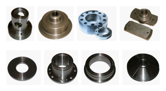
Product Instruction: MP is having a full line of Piston Rods and Extension Rods for triplex and duplex pumps. They are all made by forged premium-grade alloy steel, with thermal refining treatment, which results in the excellent mechanical characteristics.+MORE
Product Instruction:Crosshead is the significant parts of the power end system for drilling mud pump, the pump transmit power to the fluid end system through the cross head assembly. Crosshead is made of the ductile iron by casting process;it has high accuracy and precious dimension and no deformation.+MORE

F 1000 mud pump for oil drilling have features of solid and compact structure, small volume, good and reliable performance. It can meet the drilling requirements such as high pressure and big displacements whether in land drilling or off-shore drilling.
F 1000 mud pumps have a longer stroke and can be operated at a lower stroke, thus improved the water supplying performance effectively and extended the lifetime of mud pump fluid end parts greatly.

A wide variety of f1600 mud pump parts options are available to you, such as 1 year, not available and 2 years.You can also choose from new, f1600 mud pump parts,as well as from energy & mining, construction works , and machinery repair shops f1600 mud pump parts, and whether f1600 mud pump parts is 1.5 years, 6 months, or unavailable.

Tom BS pump has been conpetely assembled and test operated under pressure before being shipped to the field. Unless otherwise instructed, the lubrication is drained from the power end. Before putting the pomp into serTice, the following precautions and operations mast be performed or checked.
The skid under the BS pumps are suitable for most any type of installation. It should be noted, however, that the box type construction of the power frame has high resistance to bending but relatively le b b resistance against twist. Therefore, the support under the pump must be level and adequate to support the weight and operating forces exerted by the pump.
In land installations, a mat of 76md x 305nn boards laid side crosswise to the pump skids for the entire length, or at a minimum, at the points indicated in Fig. 2, is usually sufficient. The boards should be a few feet nider than the width of the pump skid runners. Wet or marshy locations may require a more stable foundation.
On permanent installations such as barge, platform,structural base, or concrete slab, "where pump skids arebolted dowm, it is essential tkat the skids be properlyshinned to prevent possiblity of twisting or distortingthe power frame. The pump Bkids mast sit solid on allshim points with bolts loose.
On barge installations, tbe pump skids are generallybolted down to T-beams running parallel and in line withthe pump skids. Install shims at points shown in Fig, 2and 3 and observe caution of proper shinning to preventtwist or distortion. -
On installations where the power unit or electric motor is mounted integrally with the pump skids, the preferred installation wonld be to set the pump package on the T-beari skids and proTide retention blocks rather than bolts to hold it in place. This will allow the pinup to "float* and mininize the transfer of barge deck or platform distortion into the frame.
Adjust the belt tension by moving the sheares apart until all of the sag has just been eliminated from the tight aide of the belt and sane of the belta on the slack side. Then increase the centers approximately 13HJ (l/2 ") for each 254Gmm (100") center distance. Example: On 318Qnm (150*) center, move pump and additional 19. 5nm (3/4 *) .
The pump drive chain lubrication system on the majority of BS pomps is an independent system having I its own oil pomp, reservoir, and drive. Fill chain case to the indicated level with a non-detergent oil as follows: Ambient temperature abore 32° F (0*0) SAE-30 Ambient temperature aboTe 32° F (O"C) SAE-20
1. 06 kg. cm2) - Volume of oil being applied to chain. - Condition of nozzles in spray tube. - Condition of oil pump driTe (V- belts or chain)
NOTE: Oil pressure may be adjusted with the pressure relief adjusting screw on the rear of the pump housing. Pressure drops may also indicate suction and discharge filter screens need cleaning. t"
IndiTidual installation conditions will dictate the design of the suction system. The suction of the BS F- series pumps must hare a poeitire head ( pressure) for satisfactory performance. The optimum suction manifold pressure is 20- 30 psi (0.14 - 0. 2lMpa) for maximum Tolmnetric efficiency and expendable parts life. This head pressure is. best supplied by a 5 z 6 centrifugal pump with 40h. p 1150 rpm electric motor. This type of drite requires a derice to automatically start and stop the centrifugal pump motor simultaneously with the triplex pump. On DC electric powered rigs a signal can usually be supplied from the DC control panel to energize a magnetic starter when the mud pump clutch air line will proride a set of contacts for energizing the magnetic a- a
Under sane conditions the BS F- Series pumps may be operated without a charging pump, prorided the fluid level in mad pits is higher than the top of the liners, L fluid being pumped is low Tiscosity and suction line must be short, straight and of at least the same diameter as j suction manifold inlet.
The suction lines should be piped with Talve arrangementsso the charging pump can be by-passed bo operation can becontinued in eYent of charging pump failure or formaintenance. Operation without a charging pump can beimproTed by replacing the auction valve springs with aweaker spring. — ÿ
Do not pipe the return line from the shear relief valve Iback into the suction system as a relief TalTe operationwill cause a sudden pressure rise in the system vastly Igreater than the system pressure ratings, resulting indamage to manifold, suction desurger and centrifugal pump.
PREPARATION OF POWER ENDI Toox BS pump has been completely assembled and test operated before being shipped to the field. Unless otherwise instructed, the lubrication is drained from the r
power end, and the expendables are remored from the fluid end for storage protection. Before operating the pump, the following mast be performed or cheeked.nID 1. Power End Lubricat ion " J I
flush by remoring the pipe plugs on each side of the pump. Refer Item 2. Pig. .7.[I Add the proper type and quantity of lubrication in the power end. Refer to lubrication plate on pomp frame for type and quantity required.
Recheck oil lerel after pump has operated for a period of 15 minutes. Shut pump down and allow approximately fire minutes for the oil lerel to equalize. Check atH" oil leiel gauge, Item 1, Pig. 7. It is usuallyV necessary for a few more gallons of oil to be added due to a certain amount being retained in the croeshead area and frame caYitiea.
: } With reference to Figure 4A, remoTe the diaphragm stuffing box and plate (1) and rotate pump so that cr os ahead is at the front of the Btroke, Thoroughly clean the front of the crosshead and the face of the crosshead extension rod. Insert alignment boss on
Stationary spray type haie been used on BS F-series pumps Ref. Fig 5. It consists of a fixture (I), a pipe (2) and a spray nozzle (3), irhich applies cooling fluid in the form of a spray to the piston and liner area. Adjust cooling irater supply to the manifold so that a spray approximately 305nn long is being discharged from -each spray nozzle. Inspect spray nozzle operation rery often. making sure the nozzle is pointed directly at the piston.
Cooling fluid be thanfuaed from pump (Item 3. Fig. 6) and Water tank (Item 5 Fig 6) to the manifold on the frame. Adjust regulating TalTe (item 4 Fig. 6) to apply as much water as possible to the liners without splashing back on A-lfi nthe croaahead extension rods and diaphragm staffing" boxplate. 40L (lO-gallons) per minute per liner is thepreferred f low rate. If water is allowed to splash onthe croashead extension rods, some of the water will workback into the power end to contaminate the lubricationoil.
Vahea and Seats iRemoTe all three discharge Talre pot corers (1), and thethree cylinder heads (2) and plugs (10) , and thoroughly Iclean all machined surfaces in the fluid end with a goodcleaning solrent. iMake sure all Talre seat bores are VERY CLEAN AND DRY (free of dirt, grease, anti-rust compound,remote all burrs or nicks with a fine emery etc. ) and cloth, using lcircular motion around seat surfaces.THOROUGHLY CLEAN AND MY the ralre seats and install Isuction and discharge TaWe seats into the raWe potbores. Drire seats firmlj into place with a bar* and Ihanmer. In stall Talres and springs and the other parts.
Install fluid baffle (11), fig. 8. 8A on end of crosshead lextension rod. BS F-500, BS F-800, BS F-1000 ASSEMBLY OF FLUID END. PARTS
A cross-aection through the fluid end for BS F-500, BS F-800, and BS F-1000 is shown in Pig. 8. With reference to Fig. 8, clean and assemble the fluid end parts in the following manner:
Install rear liner seal (5) and push into position against liner shoulder. Ref. Fig. 8. Slide liner cage (8) into fluid end, align one hole in the cage with lower valve pot bore. Set lower ralve guide (8) over ralve stem through lower hole in cage with the wings on the guide turned crosswise to the pump. Press downi0 A-20
on the" guide, compressing the valve spring (7) until the guide can be rotated l/4 tnrn and seat into place underneath the cage. Insert the lover Talve guide locking clip (9) through" the pad eyes on the lover valve guide and rotate dip to the right to lock the valve guide tight against the OD of the liner cage. It may sometimes be necessary to put more or less bend in the center of the clip to make it retain the guide tightly while the clip handle snaps into position on the right hand side. Cylinder Head & Insert the outer seal (5) in the fluid end bore against the liner cage. Slide the cylinder head plug (10) into fluid end. Apply a liberal coat of grease to both mating thread surfaces of the cylinder head (2) Screw- cylinder head in and tighten with wrench furnished with pump and sledge banner. Fluid leakage through the weep hole will indicate a defective seal or loose cylinder head. DO NOT plug weep holes as this can result in severe damage to sylinder head threads, thread rings, etc., in eTent of a liner seal failure.
With reference to Fig. 8A A cross- section through the fluid end for BS F -1300/1600 is shown in Fig &A. clean and assemble the fluid end parts in the following manner.
Note: All of the parts in this fluid end assembly are designed with metal to metal seating to alleiiate friction wear from breathing action encountered in modern high pressure pump operation. For this reason it iB essential that all parts be clean and free of rust, nicks and burrs before being assembled.Liner Install wear plate seal (l) in counterbore of fluid end. Slide wear plate (2) oTer studs until it seats BS F-1300. BS F-160Q ASSEMBLY OF FLUID END PARIS @
The shear relief valve ( 3) is installed on the ! > discharge manifold for the purpose of protecting the ! pump from excessively high pressure overloads. The relief valve must be installed so that it will be directly exposed to the mud DO NOT POT ANY TYPE OP . SHOT OFF VALVE between, the relief ralre and the J manifold. Pipe the discharge side of the relief valve* directly into the mad pit with as few. turns in the line as possible. IT IS NOT RECOAENDED for the discharge Bide of the valve to be piped into the sue t ion line of the pump.
O Precharge dampener before .a tar ting up pump. Precharge pressure should not be more than 2/3 of the pomp discharge pressure, or a maximum of 4. fiMpa.
Proper lubrication of the moving parts in any piece ofmachinery is tie moat important single factor affectingits ultimate life. To obtain maximum trouble -freeservice life from the poorer end of the BS pranp, it isnecessary to perform routine maintenance care andinspections to insure the proper amount of CLEANlubricant is being provided.The F-Series pumps utilize the controlled flow oil bath splash and pressure system to lubricate the entire powerend. The type of pressure system prorided in each individual pump will govern the minimum SHI at which thepump can be operated, i. e. pumps which haTe pressure lubrication only to the main and pinion bearingst hare aminimum rated speed of 40 SPM Pumps in which pressurelubrication is provided to the main. pinion, andctosshead bearings and crosshead compartments may beoperated at a minimum Epeed of 25 SM proTided there isa* minimum of 0. 035Mpa (5PSI) oil pressure. .
CAUTION: The pressure lubricating system can be provided with an externally mounted oil pomp driren through V- belts or an internally mounted oil pump driven from the main gear. When an internally mounted oil pump is used, the direction of rotation of the pinion shaft must be as shown in Fig. 10. B-2 rfcf r
haiing to gbe attention to hole alignment. This permits the installation of croashead pins fraa either direction. For BS P-600 pump. Oil passage from the top of the crosshead guid compartment to the crosshead bearing is shown in Pig. 11A. Oil accumulates in the compartment over the crossheads. The oil runs through the oil passage, (1) ( 2) and crosshead pins oil passage (3), and on to the crosshead pin bearing. As noted, the duplicate set of passageways (3) in the crosshead pin permits the crosshead pins to be rotated without hating to gire attention to hole alignment. This permits the installation of crosshead pins from either direction.
The total pressure lubrication system, incorporating the oil pump for the BS F-series pumps, is shown in Figure 12 B-4 p
A pressure relief raWe (6) is mounted, to the manifold block (2) to keep excess pressure from damaging oil pump and drive. The relief ralre is preset at 0. 2.7I4pa (40 PSI) and mnst not be tampered with.
When installing the internally mounted oil pomp ( 9 Fig. 12), position pump so that the back face of the drive gear is flash and parallel with the edge of the main gear, and gear teeth haTe 0. 60~ 0. 9 tern backlash.
m Fig. 13 B-fi r fRef. Pig. 13, Adjust tit 7- be It drire (2) to a point where tie two halves of the belt can almost be "pinched* together between the thumb and fingers at the center of the driTe. Orertightening can cause premature failure of the pump.
Adequate lubrication of the moving parts is, as stated, the most important single factor affecting the ultimate service life of the pump, CARE AND MAINTENANCE of the system is the sole responsibility of the operator or cren to which it has been assigned, and the extent to which „ ~ this is applied will determine the amount of ,trouble-free - j service life that will be obtained. : !ÿ The lubricant recommendations shown below, on the name plate on the side of the pump, are the result of extensive field tests. Substitutions b hou Id be made only ill extreme emergencies.
ONCE EACH SIX MQtflUb, or more often if oil becomescontaminated with abrasive particles or corrosiTecompounds, drain and flash the oil reservoir ew lubricant.Oil drains are located on either aide of the pump frame.
During the flushing procedure, thoroughly clean the oiltroughs and the compartment in top of the crosshead guide.Also clean or replace the filter element in the airbreather cap and clean suction screen. Remove coyer s fronsettling chamber and purge out contaminants before addingnew oil.Routine inspection on condition of oil should be made ascondensation of moisture in the air, intrusion of mud,water or dirt, can necessitate a more frequent oil change.
A settling chamber is located in the forward area of thepower end f loor, Contamination in the oil splashed intothis area is allowed to settle out and should be drainedout of the pump through the clean out covers located onthe frame wall underneath the crosBhead inspection doors.
Once each month, remove clean out covers on both sides ofpump to drain contaminated oil from settling chamber.Approximately 15-gallons of oil will be lost; replenishthe main reservoir to compensate for the amount drainedout. I
2. Safety wires - Check safety wires on all bolts including the main bearing hold-down bolts and eccentric bearing retainer bolts, Replace any broken wires after retightening the bolts. Refer to crankshaft assembly section for bolt torque requirements. 3. Oil lines - Check all oil lines to insure they are intact and free of obstructions. Check oil pump suction hose for damage or flat areas.
6. Main gear and pinion teeth - Inspect the condition of the main gear teeth and pinion gear teeth for any indications of abnormal wear. During the initial break-in period, there will be some ; pitting on the face of the gear teeth. This isn referred to as "initial pitting* and is not harmful to the life of the gear. However, if routine inspection indicates the degree of pitting continues to increase,m immediately contact the pump manufacturer for a more thorough inspection of the gear.
Although the basic construction of the rarious sizes ofBSF pumps raries somewhat, they all haie one reryimportant detail in common roller bearings. A rollerbearing is a precisely built machine within itself;therefore, careful handling is required in order toobtain the long service life and high load carryingcharacteristics associated with anti-fr ication bearings.
It is always necessary to completely replace any roller bearing that fails, even though only one part of the bearing shows damage. Since the running clearances of these bearings are extremely small, excessive clearances, worn or grooTed raceways, and any pitting or flaking of the parts is indicative of failure and the entire bearing should, be changed as soon as possible.
The suction, flange has a standard thread connection (8" NPT for BS F-500, 10* NPT for BS F-800, 12* NPT for BS F-1000/l300/ 1600) and is custom made to match the companion flange on the pump suction manifold. The connection is sealed off by an 0-ring seal.
crankshaft is mounted in the pump frame, the running clearance in main bearings will require that a simultaneous Bet of dial indicator readings be taken at the end of the shaft and the face of the gear; the actual face runout at any point being I the difference between these readings.
b. Install the outer races of the eccentric bearingB (13) I and the outer race retainer ring ( 3) in the three eccentric straps. Outer race retainer ring must be positioned so that oil scoop ij at tie bottom when I pump ib at mid-stroke. frighten retainer bolts (4) to the following torque; safety wire heads.
In order to obtain a more precise fit between tie mainbearing housing and the frame bore on BS P-Series pumps,the installation procedures outlined below are to befollowed (Refer to Pig. 16)
NOTE: For BS F-800, BS F- 1000, BS F- 1300, BS F-1600 upper and lower croashead guides are NOT interchangeable. In these pumps, the guides are machined so that the lower guide places the
TkoroagEl"ÿferreah; tie frame" fforeani tie making surfaces: "CÿL ÿ£.of tie*"",frame wall- and1 erogsSeadT guide (Position A1 — r-SSgfr .ÿTÿ"Tieaeÿscrface£" ~ABS0II7rEIir "FEES OF "DIET iiSjV." FOREIGK MATERIAL- in order -..for crossiead- guide ta gire .~z==k- Tresis-.- proper "alignment between tie power end and fluid end- ÿ•H-" . parts. * "*• "ÿ. "T?V -"r:ÿ ÿ "• ÿ rt ÿ— ÿ . x -* -v ÿ" *»• ."»* #V*p,i * i* ** t ÿ
5. Check mating surfaces (position A} for metal-to-metal make-up by Attempting to insert a 0. 025mu - 0. 050nn feeler gauge between tie two parts.
The croaaheada in the pumps can be installed through thefront (f laid end) or back end of the croaahead guide.Reference Fig. 18. ISA. When inatalling croaaheada, obaervethe following precantiona:
.Install the center croaahead first. Crosshead pin is installed through the top of the pomp by removing the inspection corer. Slide crosshead pin into bore bat do not seat taper until the crosshead pin retainer (2) Fig. ISA has been installed NOTE: If old crossheads are to be reused, inspect the sliding surfaces for *ear or scoring. If necessary, the crossheads may be Buitched to opposite sides of the pump and rotated 180° to proTide a smooth surface for the bottom of the crosshead The center crosshead can be rotated 180° and the crosshead pin installed from the opposite side of pomp.
4. If the center Line of the extension rod is more than 0. 381mn (0. 015 ") Io* in the diaphragm plate bore, shims should be inserted tinder the lower guide- to bring the extension rod back to center, provided there is ample clearance between the top of crosshead and upper crosshead guide. It is normal for the lower guide to wear more at the rear dne to heavier loading at this point because of the angle of the eccentric strap. It is permissable to shim the guides on a taper if it iB done accurately to proTide firm support for the guide. Do not shim guides to leas than 0. 50nrn (0.020*) clearance. Iiar.gft cmahead clearances ire acceptable due to characteristics of triplex pump operation, the crosshead pressure is always on the lower guide.
For many years, the fluid end of a pump iras considered anon-wearing part which did not cause any concern otherthan possible infrequent repairs or replacementsresulting from fluid cuts or washouts. However, thehigher pressures of the present-day drilling requirementshave resulted in higher stresses being imposed on thefluid end which, when combined with the corrosivecharacter


 8613371530291