
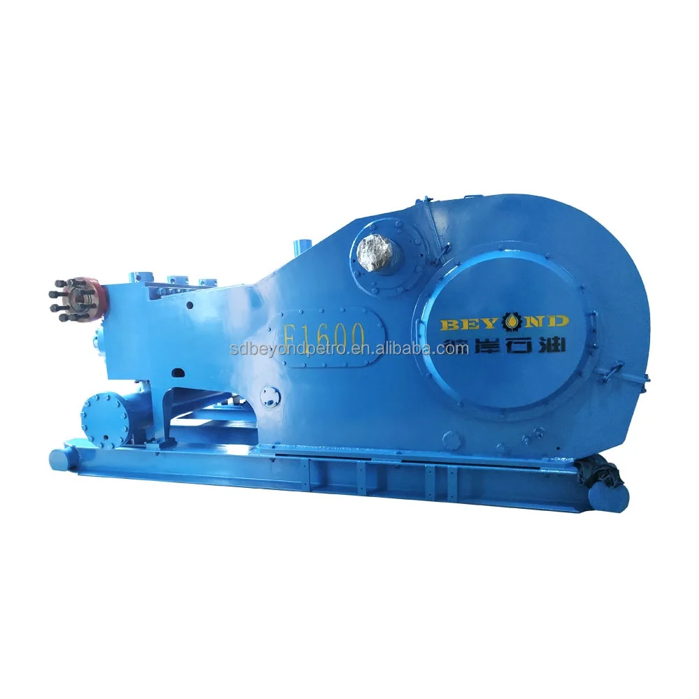
f1600 mud pump for sale free sample
A wide variety of mud pumps f 1600 options are available to you, such as 1 year, not available and 2 years.You can also choose from new, used mud pumps f 1600,as well as from energy & mining, construction works , and machinery repair shops mud pumps f 1600, and whether mud pumps f 1600 is 1.5 years, 6 months, or unavailable.
If you are supplying pump supplies, you can find the most favorable prices at Alibaba.com. Whether you will be working with piston type or diaphragm type systems, reciprocating or centrifugal, Alibaba.com has everything you need. You can also shop for different sizes bomco f1600 mud pump wholesale for your metering applications. If you operate a construction site, then you could need to find some concrete pump solutions that you can find at affordable rates at Alibaba.com. Visit the platform and browse through the collection of submersible and inline pump system, among other replaceable models.
A bomco f1600 mud pump comes in different makes and sizes, and you buy the tool depending on the application. The pump used by a filling station is not the one you use to fill up your tanks. There are high flow rate low pressure systems used to transfer fluids axially. On the other hand, you can go with radial ones dealing with a low flow rate and high-pressure fluid. The mixed flow pump variety combines radial and axial transfer mechanisms and works with medium flow and pressure fluids. Depending on what it will be pumping, you can then choose the bomco f1600 mud pump of choice from the collection at Alibaba.com.
Alibaba.com has been an excellent wholesale supplier of bomco f1600 mud pump for years. The supply consists of a vast number of brands to choose from, comes in different sizes, operations, and power sources. You can get a pump for residential and large commercial applications from the collection. Whether you want a water pump for your home, or run a repair and maintenance business, and need a supply of bom co f1600, mud pump, you can find the product you want from the vast collection at Alibaba.com.therther it is for refrigeration, air conditioning, transfer, or a simple car wash business, anything you want, Alibcom. it has easy to find the right youco for your00.

This website is using a security service to protect itself from online attacks. The action you just performed triggered the security solution. There are several actions that could trigger this block including submitting a certain word or phrase, a SQL command or malformed data.

This website is using a security service to protect itself from online attacks. The action you just performed triggered the security solution. There are several actions that could trigger this block including submitting a certain word or phrase, a SQL command or malformed data.

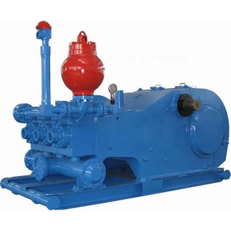
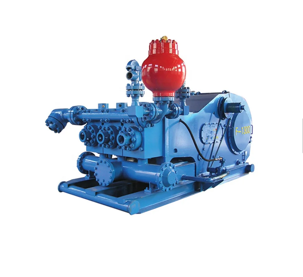
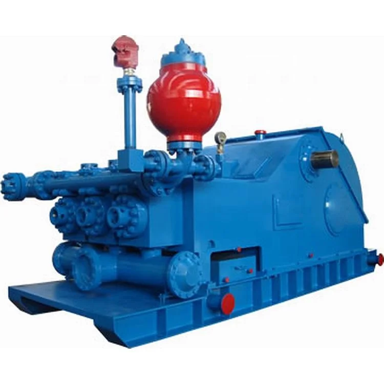
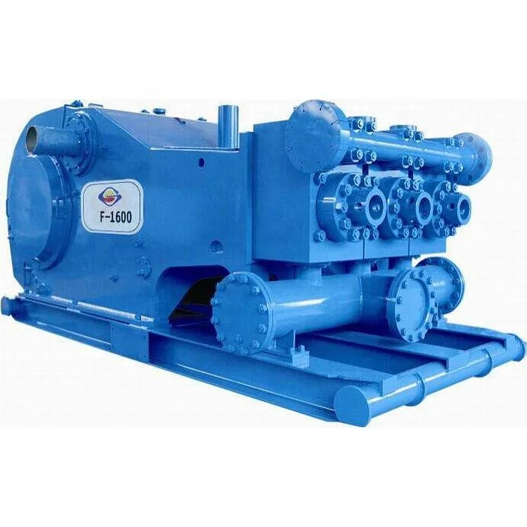
The F Series mud pumps can meet the requirements of the same manufacturing technique and quality level as those of F series mud pumps of EMSCO, IDECO, GARDNER DENVOR, OILWELL etc. Now, F series mud pumps (from F-500 to F-2200) have been produced in batches and sold to many abroad oilfields. Your order for F series mud pumps is cordially welcome.
We export-orientated mud pump parts, including liners, pistons, piston inserts, valve inserts, oil seals, rod packing, fluid ends etc.. All of them meet or exceed DIN and API standards and have been exported to U.K., Germany, USA, Canada, Pakistan, Middle East, and so on.

This website is using a security service to protect itself from online attacks. The action you just performed triggered the security solution. There are several actions that could trigger this block including submitting a certain word or phrase, a SQL command or malformed data.
Manufactured to withstand the toughest drilling and environmental conditions, our K-Series triplex mud pumps are ideal for all drilling applications. This legacy product features a balanced forged-steel crankshaft and Southwest Oilfield Products ‘L” Shaped modules which is essential to minimize wear, noise, and operating vibrations. These attributes are essential when drilling deeper high pressure formations, long laterals and when handling corrosive or abrasive fluids and slurries.
Every American Block triplex mud pump is manufactured and fully load tested before leaving our manufacturing campus, and is available in sizes ranging from 800 HP to 2200 HP. The American Block K1600 HP Mud Pump is also available in a 2000 HP up-grade version, when more HP is needed in the same 1600 HP footprint.

The bearings can meet the challenges of applications faced with heavy radial loads and high speeds. Accommodating axialdisplacement (except for bearings with flanges on both the inner and outer rings), they offer high stiffness, low friction andlong service life.
contaminants, water and dust, while providing lubricant retention and contaminant exclusion. This provides lower friction and longer service life. Split bearings are intended primarily for bearing arrangements which are difficult to access, such as crankshafts, where they simplify maintenance and replacements.
This website is using a security service to protect itself from online attacks. The action you just performed triggered the security solution. There are several actions that could trigger this block including submitting a certain word or phrase, a SQL command or malformed data.
Cylinder linerflange is the main parts of drilling mud pump in the system, we can produce all kings of cylinder head flange. They are exchanged with all major pump models. The parts are precisely made to meet or exceed OEM specification.
2. The cylinder liner flange is mounted at the back of the cylinder for the indirect fixing of the cylinder liner, which is fixed on the cylinder by stud bolts. The cylinder flange is connected with the cylinder cover and pressed against the cylinder liner tightly .
4. Manufacturers supply the supporting accessories for the mud slurry pump manufacturers for many years , with rich experiences, and have the reliable product quality, good reputation in the industry.
A Mud Pump Cylinder liner flange can also be a plate or ring to form a rim at the end of a pipe when fastened to the pipe (for example, a closet Mud Pump Cylinder liner flange). A blind Mud Pump Cylinder liner flange is a plate for covering or closing the end of a pipe. A Mud Pump Cylinder liner flange joint is a connection of pipes, where the connecting pieces have Mud Pump Cylinder liner flanges by which the parts are bolted together.
Although the word Mud Pump Cylinder liner flange generally refers to the actual raised rim or lip of a fitting, many Mud Pump Cylinder liner flanged plumbing fittings are themselves known as "Mud Pump Cylinder liner flanges":
Common Mud Pump Cylinder liner flanges used in plumbing are the Surrey Mud Pump Cylinder liner flange or Danzey Mud Pump Cylinder liner flange, York Mud Pump Cylinder liner flange, Sussex Mud Pump Cylinder liner flange and Essex Mud Pump Cylinder liner flange. Surrey and York Mud Pump Cylinder liner flanges fit to the top of the hot water tank allowing all the water to be taken without disturbance to the tank. They are often used to ensure an even flow of water to showers. An Essex Mud Pump Cylinder liner flange requires a hole to be drilled in the side of the tank.
There is also a Warix Mud Pump Cylinder liner flange which is the same as a York Mud Pump Cylinder liner flange but the shower output is on the top of the Mud Pump Cylinder liner flange and the vent on the side. The York and Warix Mud Pump Cylinder liner flange have female adapters so that they fit onto a male tank, whereas the Surrey Mud Pump Cylinder liner flange connects to a female tank.
A: First we discuss order details, production details. Then we issue you an PI for your confirmation. You will be requested to do pr-e paid full payment or deposit before we go into production. After we get the deposit, we start to process the order. We usually need 15-25 days if we don"t have the items in stock. Before production has been finished, we will contact you for shipment details, and the balance payment. After payment has been settled, we start to prepare the shipment for you.

01 8/11/2014 For Information T. Schutt J. Olson B. Schumer Rev Date (dd/mm/yyyy) Reason for Issue Prepared Checked Approved
Technical Specification Pre-Shipment And Storage PS-4030 02 Preservation For New-Build NOV Triplex Mud Pumps
Product Information Bulletin Triplex Mud Pumps Power 01-05-01-MP 06 End Lubrication Oil Additive and wear-in Period
Procedure The Use of and Application of Safety Wire for ASP00019 A Secondary Retention Design Specification Design Torque Standard DS00008 F General Lubrication Bulletin General Lubrication Bulletin CE-538E 06 for CE Drilling Equipment
RIG/PLANT REFERENCE REFERENCE DESCRIPTION Triplex Mud PumpADDITIONAL CODE SDRL CODE TOTAL PGS This document contains proprietary and confidential information National Oilwell Varco which belongs to National-Oilwell Varco, L.P., its affiliates orREMARKS subsidiaries (all collectively referred to hereinafter as "NOV"). It is loaned for limited purposes only and remains the property of NOV. 11000 Corporate Centre Drive Reproduction, in whole or in part, or use of this design or Suite 200MAIN TAG NUMBER DISCIPLINE distribution of this information to others is not permitted without the Houston, Texas 77041 express written consent of NOV. This document is to be returned to NOV upon request and in any event upon completion of the use for U.S.A.CLIENT PO NUMBER which it was loaned. This document and the information contained and represented herein is the copyrighted property of NOV. Phone: +1-281-854-0400 National Oilwell Varco Fax: +1-281-854-0607CLIENT DOCUMENT NUMBER DOCUMENT NUMBER REV
02 12.09.2012 For Information RLP BTS GDH 1 15.08.2006 For Information GDH GDH GDH 0 07.05.1990 For Information GDH GDH GDH Rev Date (dd.mm.yyyy) Reason for issue Prepared Checked Approved
Revision Change Description 0 Initial Release 1 Updated Entire Document 02 Added NOV Standard Front Cover & Updated Page Formats
1 SCOPE.............................................................................................................................. 42 MANUFACTURING PLANT PRESERVATION PRIOR TO PAINT .................................. 43 MANUFACTURING PLANT PRESERVATION AFTER PAINT ........................................ 54 STORAGE AT MANUFACTURING PLANT OR FINAL DESTINATION .......................... 65 STORAGE PREPARATIONS FOR MAIN DRIVE MOTORS. ........................................... 66 PRESERVATION PROCEDURE WHEN STORAGE EXCEEDS SIX (6) MONTHS OFINITIAL PRESERVATION. .......................................................................................................... 67 START-UP AFTER STORAGE ........................................................................................ 78 CONTACT DETAILS FOR NOTED CORROSION PREVENTATIVE MATERIALS ......... 79 EXHIBIT 1 ......................................................................................................................... 810 EXHIBIT 2 ......................................................................................................................... 9
This specification covers the preservation and storage procedure for shipment of new-build NOV Triplex Mud Pumps shipped from the manufacturing plant.
This specification is intended to provide preservation of new-build NOV Triplex Mud Pumps for six (6) months from the shipment of the mud pump from the manufacturing facility. If a pump is to be stored for a period of time exceeding six (6) months, additional precautions should be taken as outlined in this specification.
National Oilwell Varco recommends that all pumps are inspected for any signs of corrosion and for proper preservation at a minimum every three (3) months for pumps stored outside and every six (6) months for pumps stored indoors.
Drain all water and clean out liner wash tank. Remove drain plug in bottom of liner wash pump and drain water then reinstall plug. Remove discharge flange from liner wash pump and pour one (1) pint of inhibiting oil-based concentrate (Cortec VpCI 329 Vapor Corrosion Inhibiting oil-based concentrate or equivalent) into liner wash pump. Rotate two (2) revolutions by hand to distribute the product. Re-install discharge flange.
Drain all oil from pump power end sump and remove crosshead covers and inspection covers. Clean out oil sump as per National Oilwell PS-3081 (Mud Pump Cleanliness). Spray all internal machined parts of power end and crosshead area with inhibiting oil-based concentrate (Cortec VpCI 329 Vapor Corrosion Inhibiting oil-based concentrate or equivalent). Rotate pump turn and re-spray. Pour quantity of inhibiting oil-based concentrate specified in the table below into power end sump.
Mud Pump Models Quantity of Inhibitor 14P, FC 2200 5 Gallons 12P, 10P, HD or A1700/1400PT, FB/FC/FD 1600, FB 1300 3 Gallons 9P, 8P, B or A850-1100PT, F/FD 1000, F 800 2 Gallons 7P, A600PT, FD 500 1 Gallon
For pumps equipped with chain drives, spray internal machined parts inside chain cases with inhibiting oil-based concentrate (Cortec VpCI 329 Vapor Corrosion Inhibiting oil based concentrate or equivalent).
Remove fluid end valve covers, seals, valves springs and seats and treat internal cavities of fluid ends, discharge manifold, discharge strainer block and suction manifold with rust preventative (CRC SP400 or equivalent). Coat threads with anti-seize (KOPR KOTE 10002 or equivalent) and coat bottom side of valve cover with rust preventative. Reinstall seals and fluid end valves covers hand tight. Customer liners, pistons, piston rods, valves, seats, springs and liner retention parts are not used for plant testing. These expendables are checked for preservation when packed and then shipped with the loose parts.
Remove breather and pack with loose parts for later shipment with pump. Seal breather hole with a greased solid plug. Affix a warning label near the breather opening (see Exhibit 1).
Seal all other pipe work (air, water, and electrical) with plastic caps of the correct size and style. Electrical J-boxes are to be encased in protective plastic wrap. Place two (2) one- pound bags of desiccant inside each J-box before sealing with tape. Wrap pressure gauges with bubble paper and plastic.
Spray all machined unpainted loose parts and expendables to be shipped with pump with rust preventative (CRC SP400 or equivalent). All parts will be wrapped or boxed to prevent damage.
Affix one (1) warning label (see Exhibit 2) to the power end pump cover and one (1) warning label on the fluid end assembly of the pump. Affix warning labels on each loose part container. In cases where the equipment will be boxed at an offsite export packer, a sufficient number of warning labels will be supplied with the shipment.
Indoor storage is preferred whenever possible; but if outside storage is required, ensure pump is stored away from salt water spray, sand blast or other adverse conditions. It is highly recommended that ship loose parts be stored indoors to eliminate conditions that promote condensation and direct sources of moisture.
For storage preparations for main drive motors, National Oilwell Varco recommends that the original manufacturers instructions be followed. If space heaters are supplied, the J- box plastic wrap must be removed and the heaters should be connected throughout the complete storage period.
Note: It is recommended that inspections be carried out on six (6) month cycles when pumps are in indoors and three (3) month cycles when stored outside.
Any pump that has been in storage will need a thorough inspection prior to start-up to insure it has not been damaged in any way and that all parts are properly in place. Failure to observe the following points can result in serious damage. Before servicing the pump, the power end sump and chain drives housings will need to be drained of any inhibiting additive. The Cortec brand products used for preservation are compatible with all lubricating oils and need not be totally removed when putting equipment into service.
TRIPLEX MUD PUMP GDH 02PREPARED BY DATE CHECKED BY DATE
DOCUMENT TITLE: Commissioning Procedure, FB/FD-1600 Triplex Mud Pump DOCUMENT OR DRAWING NO. PAGE 2 of ENGINEERING EDN-1688 12SUBJECT COMMISSIONING PROCEDURE, FB/FD-1600 APPROVED REVISED DATE REV.
TRIPLEX MUD PUMP GDH 02PREPARED BY DATE CHECKED BY DATE
1. Power End.................................................................................................. 3 2. Main Electric Drive Motors 3 3. Auxiliary A/C Motors. 4 4. Instrumentation........................................................................................... 4 5. Liner Wash System..................................................................................... 4 6. Fluid End.................................................................................................... 4 7. Suction Dampener/Desurger....................................................................... 4 8. Pulsation Dampener.................................................................................... 4 9. Pressure Gauge............................................................................................ 5 10. Reset Relief Valve....................................................................................... 5 11. Discharge Strainer 5 12. Mud Pump Drive Assembly. 5 a. Belt Drive Units 5 b. Chain Drive Units. 5
TRIPLEX MUD PUMP GDH 02PREPARED BY DATE CHECKED BY DATE
The initial startup procedures are written to assist the operator in preparing the pump packages for normaloperation. The startup procedures are separated into two categories: Part I: Pre-Commissioning, and PartII: Commissioning Procedures. It is suggested that a copy of these pages be made for each pump to beused as a check-off sheet.
Note: The rust preventative on the internal surfaces of the pump is oil-soluble and is compatible with the lubricants recommended above. It is not necessary to flush and drain unless the preservative has become contaminated (water, sand etc.).
Megger test the motors. Check each motor separately for the correct rotation. Reconnect if necessary. Megger test the blower motors. Check blower motors for correct rotation and quantity of air flow. DOCUMENT OR DRAWING NO. PAGE 4 of ENGINEERING EDN-1688 12SUBJECT COMMISSIONING PROCEDURE, FB/FD-1600 APPROVED REVISED DATE REV.
TRIPLEX MUD PUMP GDH 02PREPARED BY DATE CHECKED BY DATE
Check to assure that all instrumentation has been properly hooked up. Check the calibration test sheets for validity and recalibrate if necessary.
Clean liner wash tank, if needed, and fill with fresh clean water. Ensure that supply hoses and spray nipples are installed correctly. Start pump and adjust regulating valve to maximum flow without splash onto the extension rods.
Check to assure that all liners, valves, and pistons are installed properly in accordance with the installation instructions. Ensure that the liner end covers are installed on the rear end of the liners. Ensure that the baffle discs are installed on the end of the crosshead extension rods. Clean grease and paint from the exposed parts of the extension rods, checking for burrs. Coat rods with a light oil.
NOTE: When charging the bladder, make sure that the mud pump suction line valve has been closed and that all pressure has been bled off of the suction manifold surrounding the suction desurger
If a dampener is used, charge dampener with a hand-operated air pump to 10 PSI (0.7 bar). Once pump operations have been started, check the operation of the suction dampener by inspecting the sight glass. Add or release air pressure through the Shraeder valve to keep the diaphragm between the midpoint and the bottom of the sight glass.
Refer to manufacturers instructions for charging the dampener. USE ONLY NITROGEN OR AIR! DO NOT USE OXYGEN. DOCUMENT OR DRAWING NO. PAGE 5 of ENGINEERING EDN-1688 12SUBJECT COMMISSIONING PROCEDURE, FB/FD-1600 APPROVED REVISED DATE REV.
TRIPLEX MUD PUMP GDH 02PREPARED BY DATE CHECKED BY DATE
Check the installation and the setting. NO SHUT-OFF VALVE is to be between the pump discharge and the relief valve. Ensure that piping from the discharge port goes directly to the mud tank/pit and is securely tied down, with a minimum downward slope of 1/4 per foot. Ensure that piping has pressure rating equal to the relief valve highest setting.
Remove the strainer screen from the housing and assure that it is clean and free from obstructions. Check the stud nuts for proper make-up torque.
Check the chain guards to ensure that the chains will not drag on the guard. Check the oil pump to ensure that the relief valve is installed on the suction side. Start the pump and ensure that the spray nozzles are spraying oil over the full width of the chain. Adjust the relief valve to 15-25 PSI output with the warm oil. DOCUMENT OR DRAWING NO. PAGE 6 of ENGINEERING EDN-1688 12SUBJECT COMMISSIONING PROCEDURE, FB/FD-1600 APPROVED REVISED DATE REV.
TRIPLEX MUD PUMP GDH 02PREPARED BY DATE CHECKED BY DATE
The power end and the fluid end have gone through rigorous tests prior to being shipped from the manufacturing site; therefore, the following recommendations for the commissioning test are made for the purpose of checking the overall unitization functions, including instrumentation, and to assure that there are no problems which may have occurred during transportation and storage.
Operation of the pump in parallel to check the SCR-Motor assignments and controls, volumetric displacement and mudline systems are at the option of the purchaser.
Check the discharge mudline to assure that all necessary valves are open. Ensure that the mud tanks are full of test fluid (mud/water) prior to startup.
Make the desired assignment of the SCR-Motor Control System to the pump motors, and open the throttle slightly. Check to ensure that charge pump and liner wash motors have started.
If no immediate problems are encountered, slowly throttle the pump to approximately 60 SPM and continue operating the mud pump while making the following inspections to assure that all systems are working properly:
Adjust the regulator valve for proper volume of cooling fluid. 10 US Gallons (38 Liter) per minute per liner. Check the coolant temperature. 150F (66C) maximum.
4) Check for interference or dragging in the belt/chain drive assemblies. DOCUMENT OR DRAWING NO. PAGE 7 of ENGINEERING EDN-1688 12SUBJECT COMMISSIONING PROCEDURE, FB/FD-1600 APPROVED REVISED DATE REV.
TRIPLEX MUD PUMP GDH 02PREPARED BY DATE CHECKED BY DATE
Pump A/C motor operating properly. Valves open for the proper volume of drilling fluid. Gauges/controls functioning properly.
Check the valve for proper relief setting. The valve should be set 10% above the pressure rating for the liner size being used. Refer to the nameplates on each side of the pump or the pump datasheet to obtain the operating pressure for that particular size liner. DOCUMENT OR DRAWING NO. PAGE 8 of ENGINEERING EDN-1688 12SUBJECT COMMISSIONING PROCEDURE, FB/FD-1600 APPROVED REVISED DATE REV.
TRIPLEX MUD PUMP GDH 02PREPARED BY DATE CHECKED BY DATE
The following are basic guidelines for conducting of an eight (8) hour operational test. The pump was test run under pressure in the manufacturing plant but with different motors and drives.
TRIPLEX MUD PUMP GDH 02PREPARED BY DATE CHECKED BY DATE
The overall performance of the unitized pump package should be continuously monitored during the eight hour test program. The following checks should be made and recorded each two hours of operation.
TRIPLEX MUD PUMP GDH 02PREPARED BY DATE CHECKED BY DATE
TRIPLEX MUD PUMP GDH 02PREPARED BY DATE CHECKED BY DATE
TRIPLEX MUD PUMP GDH 02PREPARED BY DATE CHECKED BY DATE
Triplex Mud Pump For Models: FD-500, FD-800, FD-1000 & FD-1600
RIG/PLANT REFERENCE REFERENCE DESCRIPTION Triplex Mud PumpADDITIONAL CODE SDRL CODE TOTAL PGS This document contains proprietary and confidential information National Oilwell VarcoREMARKS which belongs to National Oilwell Varco; it is loaned for limited 1530 W Sam Houston Pkwy. N purposes only and remains the property of National Oilwell Varco. Reproduction, in whole or in part; or use of this design or Houston, TX 77043MAIN TAG NUMBER DISCIPLINE distribution of this information to others is not permitted without the Phone 713-935-8000 express written consent of National Oilwell Varco. This document is Fax 713-935-8382 to be returned to National Oilwell Varco upon request and in anyCLIENT PO NUMBER event upon completion of the use for which it was loaned. National Oilwell VarcoCLIENT DOCUMENT NUMBER DOCUMENT NUMBER REV
01 15.08.2006 New Manual TMH TMH KS Rev Date (dd.mm.yyyy) Reason for issue Prepared Checked Approved
This manual is provided for guidance of those who wish to install, repair, maintain, or adjust theNational Oilwell Varco equipment covered herein. This information has been prepared with abasic viewpoint to give accurate and concise data needed to perform minor adjustments as wellas major overhauls.
This information is not elementary, as it is intended for operators and servicemen who are familiarwith drilling equipment in general. It is not intended, nor would it be possible in such limitedspace, to cover every possible condition which may be encountered. Always use good, soundmechanical practices and safety precautions.
All specifications are in accordance with Engineering designs and should be adhered to in allrepairs. Operation and maintenance information on equipment other than National Oilwell Varcosis taken in part from the various manufacturers manuals. If the equipment manufacturers issuelater instructions, or in the event of conflict, the manufacturers information will take precedenceover that shown in this manual, unless specifically stated otherwise.
Refer to the General Lubrication Bulletin for approved lubricants. If any discrepancy existsbetween the recommendations in this manual and the General Lubrication Bulletin, those in theLubrication Bulletin will take precedence.
The manual sections follow logical divisions in major components, and cover all standardproduction unless otherwise specified. Specifications and components covered are for standardequipment current at the time this manual was approved for printing.
IN ORDER TO PREVENT PERSONAL INJURY during performance of any maintenanceor inspection procedures, this equipment must be shut down and not operating. Eachmotor and generator is equipped with a motor cutout switch. This switch should be IN,and the safety bar in place, when any maintenance or inspection procedures areperformed. Employ good mechanical practices when making maintenance repairs,adjustments, inspections, etc.
When operating all mechanical and electrical equipment, all safety devices must beengaged, properly adjusted, and in good operating condition, including overtravel devicesfor traveling blocks, warning or shutdown devices for engines, etc.
PREFACE.................................................................................................................................... 31 INSTALLATION OF NEW PUMP ................................................................................... 112 SETTING THE PUMP ..................................................................................................... 11 2.1 Land Installations.................................................................................................. 113 SUCTION SYSTEM REQUIREMENTS........................................................................... 16 3.1 Caution ................................................................................................................. 164 PREPARATION OF POWER END ................................................................................. 17 4.1 Power End Lubrication.......................................................................................... 17 4.2 Installation of Crosshead Extension Rods and Diaphragm Stuffing Box Seals..... 185 PISTON AND LINER COOLING SYSTEM ..................................................................... 19 5.1 Stationary spray (View A, Fig. 6) .......................................................................... 20 5.2 Moving Nozzle ...................................................................................................... 206 ASSEMBLY OF FLUID END PARTS ............................................................................. 23 6.1 Valves and Seats.................................................................................................. 237 FD-500, FD-800 & FD-1000............................................................................................ 24 7.1 Liners.................................................................................................................... 25 7.2 Piston Rod ............................................................................................................ 25 7.3 Piston Rod Clamps ............................................................................................... 25 7.4 Liner Cage and Lower Valve Guide ...................................................................... 26 7.5 Cylinder head ....................................................................................................... 26 7.6 Discharge Valve Pot Covers ................................................................................. 268 FD-1600 .......................................................................................................................... 27 8.1 Liner...................................................................................................................... 28 8.2 Piston Rod ............................................................................................................ 28 8.3 Piston Rod Clamps ............................................................................................... 29 8.4 Lower Valve Guide and Cylinder Head................................................................. 29 8.5 Discharge Valve Pot Covers ................................................................................. 29 8.6 Discharge Manifold all models .............................................................................. 30
Your National Oilwell Varco pump has been completely assembled and test operated under pressure before being shipped to the field. Unless otherwise instructed, the lubrication is drained from the power end and the expendable parts are removed from the fluid end. Before putting the pump into service, the following precautions and operations must be performed or checked.
2 SETTING THE PUMP The skids under the National Oilwell Varco pumps are suitable for most any type of installation. It should be noted, however, that the box type construction of the power frame has high resistance to bending but relatively less resistance against twist. Therefore, the support under the pump must be level and adequate to support the weight and operating forces exerted by the pump.
2.1 Land Installations In land installations, a mat of 3 X 12 (76.20 mm x 304.8 mm) boards laid side crosswise to the pump skids for the entire length, or at a minimum, at the points indicated in Fig. 2, is usually sufficient. The boards should be a few feet wider than the width of the pump skid runners. Wet or marshy locations may require a more stable foundation.
Suitable means, such as National Oilwell Varco pump spacers as shown in Fig. 3, should be used to keep the pump anchored and the drive in alignment. National Oilwell Varco mud pump spacers provide 8-1/2 (215.9mm) adjustment. Any desired length may be obtained by lengthening the standard pipe spacer, which is made of 3 (76.20mm) extra strong pipe.
2.1.1 Permanent Installations On permanent installations such as barge, platform, structural base, or concrete slab, where pump skids are bolted down, it is essential that the skids be properly shimmed to prevent possibility of twisting or distorting the power frame. The pump skids must sit solid on all shim points with bolts loose.
On barge installations, the pump skids are generally bolted down to T-beams running parallel and in line with the pump skids. Install shims at points shown in Figs. 2 and 4 and observe caution of proper shimming to prevent twist or distortion.
On installations where the power unit or electric motor is mounted integrally with the pump skids, the preferred installation would be to set the pump package on the T-beam skids and provide retention blocks rather than bolts to hold it in place. This will allow the pump to float and minimize the transfer of barge deck or platform distortion into the frame.
2.1.2 Installation of the Drive The drive between the mud pumps and the power source, whether V-belts or multi-width chains, should be installed with the greatest care to assure maximum operating life with minimum of unexpected or undesirable shutdowns due to drive failures.
When a wrench or length of pipe is used to increase leverage in tightening draw-up bolts, it is imperative to adhere to the wrench torque values given in the chart below. This adherence is important, because in mounting the hub, the tightening force on the bolts is multiplied many times by the wedging action of the tapered surface. This action compresses the hub for a snug fit on the shaft. If the bolt tightening forces are extreme, bursting pressure is created in the hub of the mounted pulley; this pressure may cause the pulley to crack. The hub bolts should always be tightened alternately and progressively.
Before installing the V-belts, check sheave grooves for wear. Worn or rounded grooves will destroy V-belts rapidly. The side walls must be straight. Sheave grooves must be free of dirt, rust or other extrusions which could damage the V- belts.
Adjust the belt tension by moving the sheaves apart until all of the sag has just been eliminated from the tight side of the belt and some of the belts on the slack side. Then increase the centers approximately (13mm) for each 100 (2540 mm) center distance. Example: On 150 (3810 mm) center, move pump an additional (19.5 mm).
DO NOT OBTAIN BELT TENSION BY PICKING UP END OF PUMP AND ALLOWING BELTS TO TIGHTEN UNDER WEIGHT OF PUMP AS END IS BEING LOWERED TO THE GROUND.
Proper installation and maintenance of the sprocket and chain drives are essential if good service life is to be obtained. Since many factors, such as chain width, center distances, speeds, and loads must be considered when determining the allowable tolerance for sprocket alignment, no good rule of thumb can be applied. The chain alignment must simply be held as nearly perfect as possible. A more precise alignment can be made by stretching two steel wires (piano wire) along one face of the two sprockets, one above and one below the centerline, and moving one of the sprockets until the wires touch at four points. This will determine that the centerlines of the drives are parallel and the faces of the sprockets are square.
The pump drive chain lubrication system on the majority of National Oilwell Varco pumps is an independent system having its own oil pump, reservoir, and drive. Fill chain case to the indicated level with a non-detergent oil as follows:
REFER TO GENERAL LUBRICATION BULLETIN for approved lubricants and additional specifications. If any discrepancy exists between the recommendations in this manual and the General Lubrication Bullletin, those in the Lubrication Bulletin will take precedence.
- Daily check of oil level. - Daily check on condition of oil. - Frequent check on oil pressure. (5-15 psi) (.352 - 1.06 kg/cm) - Volume of oil being applied to chain. - Condition of nozzles in spray tube. - Condition of oil pump drive (V-belts or chain)
NOTE: Oil pressure may be adjusted with the pressure relief adjusting screw on the rear of the pump housing. Pressure drops may also indicate suction and discharge filter screens need cleaning.
3 SUCTION SYSTEM REQUIREMENTS Individual installation conditions will dictate the design of the suction system. The suction of the FD-series pumps must have a positive head (pressure) for satisfactory performance. The optimum suction manifold pressure is 20-30 psi (1.75-2 kg/cm) for maximum volumetric efficiency and expendable parts life. This head pressure is best supplied by a 5 x 6 centrifugal pump with 40 h.p. 1150 rpm electric motor. This type of drive requires a device to automatically start and stop the centrifugal pump motor simultaneously with the triplex pump. On DC electric powered rigs a signal can usually be supplied from the DC control panel to energize a magnetic starter when the mud pump clutch air line will provide a set of contacts for energizing the magnetic starter when clutch is engaged.
The charging pump can also be belt driven from the triplex pinion shaft charging type of drive is not as efficient at slow speeds with viscous fluids.
Under some conditions the FD-Series pumps may be operated without a charging pump, provided the fluid level in mud pits is higher than the top of the liners, fluid being pumped is low viscosity and suction line must be short, straight and of at least the same diameter as suction manifold inlet.
The suction lines should be piped with valve arrangements so the charging pump can be by-passed so operation can be continued in event of charging pump failure or for maintenance. Operation without a charging pump can be improved by replacing the suction valve springs with a weaker spring.
Suction desurgers are a very effective aid for complete filling of the liners and dampening pulsations in the suction line which results in a smoother flow in the discharge line. If your pump is equipped with a suction desurger it must be pre-charged with compressed air before operations are begun. See suction desurger manual for charging instructions.
3.1 Caution Do not pipe the return line from the shear relief valve back into the suction system as a relief valve operation will cause a sudden pressure rise in the system vastly greater than the system pressure ratings, resulting in damage to manifold, suction desurger and centrifugal pump.
4 PREPARATION OF POWER END Your National Oilwell Varco pump has been completely assembled and test operated before being shipped to the field. Unless otherwise instructed, the lubrication is drained from the power end, and the expendables are removed from the fluid end for storage protection. Before operating the pump, the following must be performed or checked:
Before installing lubricant, open inspection door in cover and check oil reservoir for possible accumulation of condensation, etc., and drain and flush by removing the pipe plugs on each side of the pump.
Add the proper type and quantity of lubrication in the power end. Refer to the Lubrication Section of this manual, or lubrication plate on pump frame for type and quantity required.
Recheck oil level after pump has operated for a period of 15 minutes. Shut pump down and allow approximately five minutes for the oil level to equalize. Check at oil level gauge, Item 1, Fig. 1. It is usually necessary for a few more gallons of oil to be added due to a certain amount being retained in the crosshead area and frame cavities.
With reference to Figure 5, remove the diaphragm stuffing box and plate (1) and rotate pump so that crosshead is at the front of the stroke. Thoroughly clean the front of the crosshead and the face of the crosshead extension rod. Insert alignment boss on crosshead extension rod into the crosshead bore and tighten the retainer bolts (2) to the following torque. Safety wire bolt heads.
Two types of piston and liner cooling systems have been used on National Oilwell Varco FD-Series Pumps -- the stationary spray type and a moving nozzle type. Ref. Fig. 6. The manifold (1) for supplying cooling fluid to the piston and liner assemblies is identical on both systems. Cooling fluid from either a remote source such as a water line, or from a pump and reservoir system unitized on the pump skids (Ref. Fig. 7) must be piped into the manifold at the connection located in the pump frame under the crosshead extension rod section.
The stationary spray cooling system consists of a spray nozzle (2) mounted on a liner end cover plate (3), which applies cooling fluid in the form of a spray to the piston and liner area. Adjust cooling water supply to the manifold so that a spray approximately *12 long is being discharged from each spray nozzle. Inspect spray nozzle operation VERY OFTEN, making sure the nozzle is pointed directly at the piston.
Inspect spray tube very often to assure that ample cooling fluid is being supplied. At routine intervals, check condition of the hose (6) which connects the spray tube to the manifold. This hose travels back and forth with the piston rod assembly, therefore must be installed so that its movement is not restricted.
With reference to Fig. 7, maintain electric motor (1) and centrifugal pump (2) according to manufacturers specifications. Rotation of the pump should be clockwise when viewed from the impeller end.
The cooling fluid is returned from the crosshead extension rod compartment to the settling chamber, and as the fluid overflows through the filter screen between the two sections of the tank, the solids are allowed to settle out. The filter screen will catch much of the foreign material floating in the fluid.
7.1 Liners Inspect liner bore again to make sure it is clean and free of foreign particles to assure metal to metal contact between the liner and fluid end. Foreign particles can cause the liner to make up in a cocked position resulting in premature wear on liners and pistons.
7.4 Liner Cage and Lower Valve Guide Install rear liner seal (5) and push into position against liner shoulder. Slide liner cage (6) into fluid end, align one hole in the cage with lower valve pot bore. Set lower valve guide (8) over valve stem through lower hole in cage with the wings on the guide turned crosswise to the pump. Press down on the guide, compressing the valve spring (7) until the guide can be rotated turn and seat into place underneath the cage. Insert the lower valve guide locking clip (9) through the pad eyes on the lower valve guide and rotate clip to the right to lock the valve guide tight against the OD of the liner cage. It may sometimes be necessary to put more or less bend in the center of the clip to make it retain the guide tightly while the clip handle snaps into position on the right hand side.
7.5 Cylinder head Insert the outer seal (5) in the fluid end bore against the liner cage. Slide the cylinder head plug (10) into fluid end. Apply a liberal coat of grease to both mating thread surfaces of the cylinder head (2). Screw cylinder head in and tighten with wrench furnished with pump and sledge hammer.
Note: All of the parts in this fluid end assembly are designed with metal to metal seating to alleviate friction wear from breathing action encountered in modern high pressure pump operation. For this reason it is essential that all parts be clean and free of rust, nicks and burrs before being assembled.
Note: FD pumps are factory equipped with jib booms and liner handling tools. If older pumps are converted to FD fluid ends a jib boom should be added to the pump frame as considerable weight is involved in handling the liner assembly.
8.6 Discharge Manifold all models A 5-1500*RTJ flange connection is provided on the discharge manifold. REMOVE flange and protect gasket area before welding (customers option) to the discharge piping. (*127mm)
Tighten discharge flange connection bolts to *1200-1600 ft. lbs. torque. To insure uniform make-up of the ring joint connection, tighten flange bolt nuts in a crisscross order. (*166- 121 meter kgs.)
8.7 Suction Flange The suction flange has a 12 (305mm) standard pipe thread connection and is custom made to match the companion flange on the pump suction manifold. The flange connection is sealed off by an O-ring seal (14 OD x 13-1/2 ID x ), (356mm OD x 343mm I.D. x 6.35mm Dia.)
NOTE: Thoroughly clean O-ring groove and face of flanges before making up connection. Flanges must make up metal to metal to insure proper seal. Tighten flange bolts to 360- 490 ft. lbs. (50-68 meter kgs.) torque.
8.8 Accessory Manifold Fig. 10 is not the standard discharge arrangement on the model FD-1600 pump, which uses the strainer cross configuration. An accessory manifold, Fig.10, is available for installation on the discharge manifold opposite the discharge end. The manifold will accommodate a discharge pulsation dampener (1) and provides two 3-6000 PSI*side outlet connections for such items as a pressure gauge (2) and a shear relief valve (3).
The flange on the accessory manifold is a 5-1500 *RTJ. Thoroughly clean ring joint groove, install ring (4) and tighten the flange bolts (5) to 1200 ft. lbs. torque. To assure uniform make-up of the ring joint connection, tighten the nuts in a criss-cross order.
The shear relief valve (3) is installed on the discharge manifold for the purpose of protecting the pump from excessively high pressure overloads.
The relief valve must be installed so that it will be directly exposed to the mud. DO NOT PUT ANY TYPE OF SHUT OFF VALVE between the relief valve and the manifold. Pipe the discharge side of the relief valve directly into the mud pit with as few turns in the line as possible. IT IS NOT RECOMMENDED for the discharge side of the valve to be piped into the suction line of the pump.
The relief valve setting should be just above the maximum pressure rating of the particular liner size being used. CHANGE SETTINGS with each liner size change. DO NOT USE ALLEN WRENCHES, WELDING RODS, or material other than that called for by the manufacturer of the relief valve, as this will affect the rating of the relief valve.
The mounting for the dischage pulsation dampener (1) is a RTJ flange with R-39 ring gasket. Before installing dampener, thoroughly clean ring groove and ring, and after setting dampener into place, tighten the 1-1/4*nut (6) to 750 ft.lbs*. torque. To insure uniform make-up, tighten nuts in a criss-cross order.
Precharge dampener before starting up pump. Precharge pressure should not be more than 2/3 of the pump discharge pressure, or a maximum of 650 PSI. (46 kg/cm)
9 LUBRICATION Proper lubrication of the moving parts in any piece of machinery is the most important single factor affecting its ultimate life. To obtain maximum trouble-free service life from the power end of the National Oilwell Varco pump, it is necessary to perform routine maintenance care and inspections to insure the proper amount of CLEAN lubricant is being provided.
The FD-Series pumps utilize the controlled flow oil bath splash and pressure system to lubricate the entire power end. The type of pressure system provided in each individual pump will govern the minimum SPM at which the pump can be operated, i.e. pumps which have pressure lubrication only to the main and pinion bearings, have a minimum rated speed of 40 SPM. Pumps in which pressure lubrication is provided to the main, pinion, and crosshead bearings and crosshead compartments may be operated at a minimum speed of 25 SPM, provided there is a minimum of 5 PSI oil pressure. (352 grams/cm)
CAUTION: The pressure lubricating system can be provided with an externally mounted oil pump driven through V-belts or electric AC motor; or an internally mounted oil pump driven from the main gear. When an internally mounted oil pump is used, the direction of rotation of the pinion shaft must be as shown in Fig. 11.
9.2 Controlled Flow Splash System The controlled flow splash lubrication system is the same for all FD-Series pumps, regardless of the type of oil pump drive provided for the pressure system. In the controlled flow splash system, the main gear picks oil up from the reservoir, and when the teeth mesh with the pinion, the oil is displaced into various troughs and compartments in the frame. With reference to Figure 13, the oil thrown into trough (7) is directed through the oil tube (8) to the two pinion bearings.
9.3 Total Pressure lubrication System The total pressure lubrication system, incorporating the internally mounted oil pump for the FD-series pumps, is shown in Figure 13.
In this system, filtered oil is supplied to the pump through the suction filter (1) and is discharged from the pump into the manifold block (2). Oil is distributed from the manifold block to the pinion shaft bearing oil line (3) and spray nozzle (3A); and to the main bearing oil line (4) and the crosshead compartment manifold block (4A) located above the crosshead compartment. The crosshead compartment manifold block (4A) distributes oil to the crosshead, crosshead bearings, and extension rods. Pumps which do not have the crosshead compartment manifold block (4A) do not have the total pressure lubrication system, and therefore have a minimum rated speed of 40 SPM.
A pressure gauge (5) is mounted on the back wall of the frame to show oil pressure being maintained in the manifold block. The oil pressure will, of course, vary with the speed of the main pump, however if a sudden pressure drop or increase occurs, refer to the section on maintenance of lubrication system for possible cause.
A pressure relief valve (6) is mounted to the manifold block to keep excess pressure form damaging oil pump and drive. The relief valve is preset at 40 PSI and must not be tampered with.
NOTE: If specified, the oil pump for the pressure lubrication system can be independently powered by an electric motor or some other type of prime mover. When the independently driven oil pump is used, some type of alarm device or power interlock must be installed to assure the oil pump is operating when the main pump is put into service.
When installing the internally mounted oil pump (9, Fig. 13), position pump so that the back face of the drive gear is flush and parallel with the edge of the main gear, and gear teeth have*.010-.015 backlash. Remove inspection plate on power end cover for access to the internally mounted oil pump and filter screen. (* .25 - .38mm)
A typical layout for the pinion shaft driven oil pump is shown in Fig. 14. The oil pump (1) is piped into the oil system through the suction and pressure connections on the bottom inside wall of the power frame. Ref. Item 10, Fig. 13. The V-belt drive (2) is adjusted by moving pump up or down on the mounting bracket.
Adjust the V-belt drive (2) to a point where the two halves of the belt can almost be pinched together between the thumb and fingers at the center of the drive. Overtightening can cause premature failure of the pump.
10 MAINTENANCE OF THE LUBRICATION SYSTEM Adequate lubrication of the moving part


 8613371530291