
forum mud pump free sample

Mud systems are essential to every oil and gas rig. To successfully transfer fluid throughout your circulating system at pressures up to 7,500 pounds per square inch you need proven and reliable products. FET’s products have 30 years of innovation and field experience in providing industry-leading technology for your mud system operations.
Our industry-recognized centrifugal pumps, gate valves, drill pipe float valves, and wash pipes provide you with robust systems that meet the high-pressure demands of today’s drilling landscape.

If you run a mud rig, you have probably figured out that the mud pump is the heart of the rig. Without it, drilling stops. Keeping your pump in good shape is key to productivity. There are some tricks I have learned over the years to keeping a pump running well.
First, you need a baseline to know how well your pump is doing. When it’s freshly rebuilt, it will be at the top efficiency. An easy way to establish this efficiency is to pump through an orifice at a known rate with a known fluid. When I rig up, I hook my water truck to my pump and pump through my mixing hopper at idle. My hopper has a ½-inch nozzle in it, so at idle I see about 80 psi on the pump when it’s fresh. Since I’m pumping clear water at a known rate, I do this on every job.
As time goes on and I drill more hole, and the pump wears, I start seeing a decrease in my initial pressure — 75, then 70, then 65, etc. This tells me I better order parts. Funny thing is, I don’t usually notice it when drilling. After all, I am running it a lot faster, and it’s hard to tell the difference in a few gallons a minute until it really goes south. This method has saved me quite a bit on parts over the years. When the swabs wear they start to leak. This bypass pushes mud around the swab, against the liners, greatly accelerating wear. By changing the swab at the first sign of bypass, I am able to get at least three sets of swabs before I have to change liners. This saves money.
Before I figured this out, I would sometimes have to run swabs to complete failure. (I was just a hand then, so it wasn’t my rig.) When I tore the pump down to put in swabs, lo-and-behold, the liners were cut so badly that they had to be changed too. That is false economy. Clean mud helps too. A desander will pay for itself in pump parts quicker than you think, and make a better hole to boot. Pump rods and packing last longer if they are washed and lubricated. In the oilfield, we use a petroleum-based lube, but that it not a good idea in the water well business. I generally use water and dish soap. Sometimes it tends to foam too much, so I add a few tablets of an over the counter, anti-gas product, like Di-Gel or Gas-Ex, to cut the foaming.
Maintenance on the gear end of your pump is important, too. Maintenance is WAY cheaper than repair. The first, and most important, thing is clean oil. On a duplex pump, there is a packing gland called an oil-stop on the gear end of the rod. This is often overlooked because the pump pumps just as well with a bad oil-stop. But as soon as the fluid end packing starts leaking, it pumps mud and abrasive sand into the gear end. This is a recipe for disaster. Eventually, all gear ends start knocking. The driller should notice this, and start planning. A lot of times, a driller will change the oil and go to a higher viscosity oil, thinking this will help cushion the knock. Wrong. Most smaller duplex pumps are splash lubricated. Thicker oil does not splash as well, and actually starves the bearings of lubrication and accelerates wear. I use 85W90 in my pumps. A thicker 90W140 weight wears them out a lot quicker. You can improve the “climbing” ability of the oil with an additive, like Lucas, if you want. That seems to help.
Outside the pump, but still an important part of the system, is the pop-off, or pressure relief valve. When you plug the bit, or your brother-in-law closes the discharge valve on a running pump, something has to give. Without a good, tested pop-off, the part that fails will be hard to fix, expensive and probably hurt somebody. Pop-off valve are easily overlooked. If you pump cement through your rig pump, it should be a standard part of the cleanup procedure. Remove the shear pin and wash through the valve. In the old days, these valves were made to use a common nail as the shear pin, but now nails come in so many grades that they are no longer a reliable tool. Rated shear pins are available for this. In no case should you ever run an Allen wrench! They are hardened steel and will hurt somebody or destroy your pump.
One last thing that helps pump maintenance is a good pulsation dampener. It should be close to the pump discharge, properly sized and drained after every job. Bet you never thought of that one. If your pump discharge goes straight to the standpipe, when you finish the job your standpipe is still full of fluid. Eventually the pulsation dampener will water-log and become useless. This is hard on the gear end of the pump. Open a valve that drains it at the end of every job. It’ll make your pump run smoother and longer.

Centerline Manu-facturing introduces the CLM 7.5 x 10D hydraulic mud pump, a pump which utilizes common fluid end parts. Its advantages are said to be its flow capacity, rated pressure, size and weight. It is designed to pump 100 percent more rated flow than a standard 5x6 and up to 3.25 times the rated pressure. However, it only has a third of the weight and 77 percent of the length.
Smart solutions. Powerful products. All Forum Energy Technologies products are reliable and easy to use; every piece designed with you in mind ─ ensuring that servicing your products is quick and stress-free.
Forum has a comprehensive offering in addition to their own high-quality product lines, by bringing together some of the most trusted brands in the industry. Their legacy includes recognizable brands like Baker SPD, Blohm + Voss, CraneSafe, Merrimac, OBI, P-quip and Pipe Wranglers.

Global Mud Pump Market, Product Type (Duplex, Triplex, Quintuplex), Driven System (Electric, Fuel Engine), Application (Onshore, Offshore), Country (U.S., Canada, Mexico, Brazil, Argentina, Rest of South America, Germany, Italy, U.K., France, Spain, Netherlands, Belgium, Switzerland, Turkey, Russia, Rest of Europe, Japan, China, India, South Korea, Australia, Singapore, Malaysia, Thailand, Indonesia, Philippines, Rest of Asia-Pacific, Saudi Arabia, U.A.E, South Africa, Egypt, Israel, Rest of Middle East and Africa) Industry Trends and Forecast to 2028.
The mud pump market is expected to witness market growth at a rate of 6.80% in the forecast period of 2021 to 2028. Data Bridge Market Research report on mud pump market provides analysis and insights regarding the various factors expected to be prevalent throughout the forecast period while providing their impacts on the market’s growth. The increase in the use of product in various industries globally is escalating the growth of mud pump market.
A mud pump or drilling mud pump refers to the type of pump that is utilized for circulating drilling mud on a drilling rig at high pressure. The mud is generally circulated down through the drill string, and back through the annulus at high pressures. These are positive displacement pumps and are ideal wherever a lot of fluid needs to be pumped under high pressure.
The increased demand for directional and horizonal drilling across the globe acts as one of the major factors driving the growth of mud pump market. The use of for moving and circulating drilling fluids and other similar fluids in several applications such as mining and onshore and offshore oil and gas, and deployment for transfering fluids at substantially high pressures accelerate the market growth. The rise in the popularity of electric mud pumps as they offer smooth operations in drilling rigs and are environment-friendly, and growth in mineral extraction activities further influence the market. Additionally, expansion of mining industry, rapid urbanization, increase in investments and emergence of industry 4.0 positively affect the mud pump market. Furthermore, surge in number if foreign investors and government initiatives extend profitable opportunities to the market players in the forecast period of 2021 to 2028.
On the other hand, lack of universal directives pertaining to applications of mud pump and stringent regulations are expected to obstruct the market growth. Lack of awareness and less adoption of mud pump is projected to challenge the mud pump market in the forecast period of 2021-2028.
This mud pump market report provides details of new recent developments, trade regulations, import export analysis, production analysis, value chain optimization, market share, impact of domestic and localized market players, analyses opportunities in terms of emerging revenue pockets, changes in market regulations, strategic market growth analysis, market size, category market growths, application niches and dominance, product approvals, product launches, geographic expansions, technological innovations in the market. To gain more info mud pump market contact Data Bridge Market Research for an Analyst Brief, our team will help you take an informed market decision to achieve market growth.
The mud pump market is segmented on the basis of product type, driven system and application. The growth among segments helps you analyze niche pockets of growth and strategies to approach the market and determine your core application areas and the difference in your target markets.
The mud pump market is analyzed and market size, volume information is provided by country, product type, driven system and application as referenced above.
The countries covered in the mud pump market report are the U.S., Canada and Mexico in North America, Brazil, Argentina and Rest of South America as part of South America, Germany, Italy, U.K., France, Spain, Netherlands, Belgium, Switzerland, Turkey, Russia, Rest of Europe in Europe, Japan, China, India, South Korea, Australia, Singapore, Malaysia, Thailand, Indonesia, Philippines, Rest of Asia-Pacific (APAC) in the Asia-Pacific (APAC), Saudi Arabia, U.A.E, South Africa, Egypt, Israel, Rest of Middle East and Africa (MEA) as a part of Middle East and Africa (MEA).
Asia-Pacific dominates the mud pump market due to the increase in number of oil wells and high investment within the region. North America is expected to witness significant growth during the forecast period of 2021 to 2028 because of the high production of oil and gas in the region.
The mud pump market competitive landscape provides details by competitor. Details included are company overview, company financials, revenue generated, market potential, investment in research and development, new market initiatives, regional presence, company strengths and weaknesses, product launch, product width and breadth, application dominance. The above data points provided are only related to the companies’ focus related to mud pump market.
The major players covered in the mud pump market report are NOV Inc., Schlumberger Limited., Gardner Denver, Weatherford, Flowserve Corporation., Honghua Group Ltd., China National Petroleum Corporation, Trevi Finanziaria Industriale S.p.A., MHWirth, Bentec, American Block, White Star Pump, Ohara Corporation, Herrenknecht Vertical GmbH, Mud King Products, Grundfos Holding A/S, Halliburton, Sulzer Ltd, KEPL, and EPIC Corporation., among other domestic and global players. Market share data is available for global, North America, Europe, Asia-Pacific (APAC), Middle East and Africa (MEA) and South America separately. DBMR analysts understand competitive strengths and provide competitive analysis for each competitor separately.

Mechanical pumps serve in a wide range of applications such as pumping water from wells, aquarium filtering, pond filtering and aeration, in the car industry for water-cooling and fuel injection, in the energy industry for pumping oil and natural gas or for operating cooling towers and other components of heating, ventilation and air conditioning systems. In the medical industry, pumps are used for biochemical processes in developing and manufacturing medicine, and as artificial replacements for body parts, in particular the artificial heart and penile prosthesis.
When a pump contains two or more pump mechanisms with fluid being directed to flow through them in series, it is called a multi-stage pump. Terms such as two-stage or double-stage may be used to specifically describe the number of stages. A pump that does not fit this description is simply a single-stage pump in contrast.
In biology, many different types of chemical and biomechanical pumps have evolved; biomimicry is sometimes used in developing new types of mechanical pumps.
Pumps can be classified by their method of displacement into positive-displacement pumps, impulse pumps, velocity pumps, gravity pumps, steam pumps and valveless pumps. There are three basic types of pumps: positive-displacement, centrifugal and axial-flow pumps. In centrifugal pumps the direction of flow of the fluid changes by ninety degrees as it flows over an impeller, while in axial flow pumps the direction of flow is unchanged.
Some positive-displacement pumps use an expanding cavity on the suction side and a decreasing cavity on the discharge side. Liquid flows into the pump as the cavity on the suction side expands and the liquid flows out of the discharge as the cavity collapses. The volume is constant through each cycle of operation.
Positive-displacement pumps, unlike centrifugal, can theoretically produce the same flow at a given speed (rpm) no matter what the discharge pressure. Thus, positive-displacement pumps are constant flow machines. However, a slight increase in internal leakage as the pressure increases prevents a truly constant flow rate.
A positive-displacement pump must not operate against a closed valve on the discharge side of the pump, because it has no shutoff head like centrifugal pumps. A positive-displacement pump operating against a closed discharge valve continues to produce flow and the pressure in the discharge line increases until the line bursts, the pump is severely damaged, or both.
A relief or safety valve on the discharge side of the positive-displacement pump is therefore necessary. The relief valve can be internal or external. The pump manufacturer normally has the option to supply internal relief or safety valves. The internal valve is usually used only as a safety precaution. An external relief valve in the discharge line, with a return line back to the suction line or supply tank provides increased safety.
Rotary-type positive displacement: internal or external gear pump, screw pump, lobe pump, shuttle block, flexible vane or sliding vane, circumferential piston, flexible impeller, helical twisted roots (e.g. the Wendelkolben pump) or liquid-ring pumps
Drawbacks: The nature of the pump requires very close clearances between the rotating pump and the outer edge, making it rotate at a slow, steady speed. If rotary pumps are operated at high speeds, the fluids cause erosion, which eventually causes enlarged clearances that liquid can pass through, which reduces efficiency.
Hollow disk pumps (also known as eccentric disc pumps or Hollow rotary disc pumps), similar to scroll compressors, these have a cylindrical rotor encased in a circular housing. As the rotor orbits and rotates to some degree, it traps fluid between the rotor and the casing, drawing the fluid through the pump. It is used for highly viscous fluids like petroleum-derived products, and it can also support high pressures of up to 290 psi.
Vibratory pumps or vibration pumps are similar to linear compressors, having the same operating principle. They work by using a spring-loaded piston with an electromagnet connected to AC current through a diode. The spring-loaded piston is the only moving part, and it is placed in the center of the electromagnet. During the positive cycle of the AC current, the diode allows energy to pass through the electromagnet, generating a magnetic field that moves the piston backwards, compressing the spring, and generating suction. During the negative cycle of the AC current, the diode blocks current flow to the electromagnet, letting the spring uncompress, moving the piston forward, and pumping the fluid and generating pressure, like a reciprocating pump. Due to its low cost, it is widely used in inexpensive espresso machines. However, vibratory pumps cannot be operated for more than one minute, as they generate large amounts of heat. Linear compressors do not have this problem, as they can be cooled by the working fluid (which is often a refrigerant).
Reciprocating pumps move the fluid using one or more oscillating pistons, plungers, or membranes (diaphragms), while valves restrict fluid motion to the desired direction. In order for suction to take place, the pump must first pull the plunger in an outward motion to decrease pressure in the chamber. Once the plunger pushes back, it will increase the chamber pressure and the inward pressure of the plunger will then open the discharge valve and release the fluid into the delivery pipe at constant flow rate and increased pressure.
Pumps in this category range from simplex, with one cylinder, to in some cases quad (four) cylinders, or more. Many reciprocating-type pumps are duplex (two) or triplex (three) cylinder. They can be either single-acting with suction during one direction of piston motion and discharge on the other, or double-acting with suction and discharge in both directions. The pumps can be powered manually, by air or steam, or by a belt driven by an engine. This type of pump was used extensively in the 19th century—in the early days of steam propulsion—as boiler feed water pumps. Now reciprocating pumps typically pump highly viscous fluids like concrete and heavy oils, and serve in special applications that demand low flow rates against high resistance. Reciprocating hand pumps were widely used to pump water from wells. Common bicycle pumps and foot pumps for inflation use reciprocating action.
These positive-displacement pumps have an expanding cavity on the suction side and a decreasing cavity on the discharge side. Liquid flows into the pumps as the cavity on the suction side expands and the liquid flows out of the discharge as the cavity collapses. The volume is constant given each cycle of operation and the pump"s volumetric efficiency can be achieved through routine maintenance and inspection of its valves.
This is the simplest form of rotary positive-displacement pumps. It consists of two meshed gears that rotate in a closely fitted casing. The tooth spaces trap fluid and force it around the outer periphery. The fluid does not travel back on the meshed part, because the teeth mesh closely in the center. Gear pumps see wide use in car engine oil pumps and in various hydraulic power packs.
A screw pump is a more complicated type of rotary pump that uses two or three screws with opposing thread — e.g., one screw turns clockwise and the other counterclockwise. The screws are mounted on parallel shafts that have gears that mesh so the shafts turn together and everything stays in place. The screws turn on the shafts and drive fluid through the pump. As with other forms of rotary pumps, the clearance between moving parts and the pump"s casing is minimal.
Widely used for pumping difficult materials, such as sewage sludge contaminated with large particles, a progressing cavity pump consists of a helical rotor, about ten times as long as its width. This can be visualized as a central core of diameter x with, typically, a curved spiral wound around of thickness half x, though in reality it is manufactured in a single casting. This shaft fits inside a heavy-duty rubber sleeve, of wall thickness also typically x. As the shaft rotates, the rotor gradually forces fluid up the rubber sleeve. Such pumps can develop very high pressure at low volumes.
Named after the Roots brothers who invented it, this lobe pump displaces the fluid trapped between two long helical rotors, each fitted into the other when perpendicular at 90°, rotating inside a triangular shaped sealing line configuration, both at the point of suction and at the point of discharge. This design produces a continuous flow with equal volume and no vortex. It can work at low pulsation rates, and offers gentle performance that some applications require.
A peristaltic pump is a type of positive-displacement pump. It contains fluid within a flexible tube fitted inside a circular pump casing (though linear peristaltic pumps have been made). A number of rollers, shoes, or wipers attached to a rotor compresses the flexible tube. As the rotor turns, the part of the tube under compression closes (or occludes), forcing the fluid through the tube. Additionally, when the tube opens to its natural state after the passing of the cam it draws (restitution) fluid into the pump. This process is called peristalsis and is used in many biological systems such as the gastrointestinal tract.
Efficiency and common problems: With only one cylinder in plunger pumps, the fluid flow varies between maximum flow when the plunger moves through the middle positions, and zero flow when the plunger is at the end positions. A lot of energy is wasted when the fluid is accelerated in the piping system. Vibration and
Triplex plunger pumps use three plungers, which reduces the pulsation of single reciprocating plunger pumps. Adding a pulsation dampener on the pump outlet can further smooth the pump ripple, or ripple graph of a pump transducer. The dynamic relationship of the high-pressure fluid and plunger generally requires high-quality plunger seals. Plunger pumps with a larger number of plungers have the benefit of increased flow, or smoother flow without a pulsation damper. The increase in moving parts and crankshaft load is one drawback.
Car washes often use these triplex-style plunger pumps (perhaps without pulsation dampers). In 1968, William Bruggeman reduced the size of the triplex pump and increased the lifespan so that car washes could use equipment with smaller footprints. Durable high-pressure seals, low-pressure seals and oil seals, hardened crankshafts, hardened connecting rods, thick ceramic plungers and heavier duty ball and roller bearings improve reliability in triplex pumps. Triplex pumps now are in a myriad of markets across the world.
Triplex pumps with shorter lifetimes are commonplace to the home user. A person who uses a home pressure washer for 10 hours a year may be satisfied with a pump that lasts 100 hours between rebuilds. Industrial-grade or continuous duty triplex pumps on the other end of the quality spectrum may run for as much as 2,080 hours a year.
The oil and gas drilling industry uses massive semi trailer-transported triplex pumps called mud pumps to pump drilling mud, which cools the drill bit and carries the cuttings back to the surface.
One modern application of positive-displacement pumps is compressed-air-powered double-diaphragm pumps. Run on compressed air, these pumps are intrinsically safe by design, although all manufacturers offer ATEX certified models to comply with industry regulation. These pumps are relatively inexpensive and can perform a wide variety of duties, from pumping water out of bunds to pumping hydrochloric acid from secure storage (dependent on how the pump is manufactured – elastomers / body construction). These double-diaphragm pumps can handle viscous fluids and abrasive materials with a gentle pumping process ideal for transporting shear-sensitive media.
Devised in China as chain pumps over 1000 years ago, these pumps can be made from very simple materials: A rope, a wheel and a pipe are sufficient to make a simple rope pump. Rope pump efficiency has been studied by grassroots organizations and the techniques for making and running them have been continuously improved.
Impulse pumps use pressure created by gas (usually air). In some impulse pumps the gas trapped in the liquid (usually water), is released and accumulated somewhere in the pump, creating a pressure that can push part of the liquid upwards.
Instead of a gas accumulation and releasing cycle, the pressure can be created by burning of hydrocarbons. Such combustion driven pumps directly transmit the impulse from a combustion event through the actuation membrane to the pump fluid. In order to allow this direct transmission, the pump needs to be almost entirely made of an elastomer (e.g. silicone rubber). Hence, the combustion causes the membrane to expand and thereby pumps the fluid out of the adjacent pumping chamber. The first combustion-driven soft pump was developed by ETH Zurich.
It takes in water at relatively low pressure and high flow-rate and outputs water at a higher hydraulic-head and lower flow-rate. The device uses the water hammer effect to develop pressure that lifts a portion of the input water that powers the pump to a point higher than where the water started.
The hydraulic ram is sometimes used in remote areas, where there is both a source of low-head hydropower, and a need for pumping water to a destination higher in elevation than the source. In this situation, the ram is often useful, since it requires no outside source of power other than the kinetic energy of flowing water.
Rotodynamic pumps (or dynamic pumps) are a type of velocity pump in which kinetic energy is added to the fluid by increasing the flow velocity. This increase in energy is converted to a gain in potential energy (pressure) when the velocity is reduced prior to or as the flow exits the pump into the discharge pipe. This conversion of kinetic energy to pressure is explained by the
A practical difference between dynamic and positive-displacement pumps is how they operate under closed valve conditions. Positive-displacement pumps physically displace fluid, so closing a valve downstream of a positive-displacement pump produces a continual pressure build up that can cause mechanical failure of pipeline or pump. Dynamic pumps differ in that they can be safely operated under closed valve conditions (for short periods of time).
Such a pump is also referred to as a centrifugal pump. The fluid enters along the axis or center, is accelerated by the impeller and exits at right angles to the shaft (radially); an example is the centrifugal fan, which is commonly used to implement a vacuum cleaner. Another type of radial-flow pump is a vortex pump. The liquid in them moves in tangential direction around the working wheel. The conversion from the mechanical energy of motor into the potential energy of flow comes by means of multiple whirls, which are excited by the impeller in the working channel of the pump. Generally, a radial-flow pump operates at higher pressures and lower flow rates than an axial- or a mixed-flow pump.
These are also referred to as All fluid pumps. The fluid is pushed outward or inward to move fluid axially. They operate at much lower pressures and higher flow rates than radial-flow (centrifugal) pumps. Axial-flow pumps cannot be run up to speed without special precaution. If at a low flow rate, the total head rise and high torque associated with this pipe would mean that the starting torque would have to become a function of acceleration for the whole mass of liquid in the pipe system. If there is a large amount of fluid in the system, accelerate the pump slowly.
Mixed-flow pumps function as a compromise between radial and axial-flow pumps. The fluid experiences both radial acceleration and lift and exits the impeller somewhere between 0 and 90 degrees from the axial direction. As a consequence mixed-flow pumps operate at higher pressures than axial-flow pumps while delivering higher discharges than radial-flow pumps. The exit angle of the flow dictates the pressure head-discharge characteristic in relation to radial and mixed-flow.
Regenerative turbine pump rotor and housing, 1⁄3 horsepower (0.25 kW). 85 millimetres (3.3 in) diameter impeller rotates counter-clockwise. Left: inlet, right: outlet. .4 millimetres (0.016 in) thick vanes on 4 millimetres (0.16 in) centers
Also known as drag, friction, peripheral, traction, turbulence, or vortex pumps, regenerative turbine pumps are class of rotodynamic pump that operates at high head pressures, typically 4–20 bars (4.1–20.4 kgf/cm2; 58–290 psi).
The pump has an impeller with a number of vanes or paddles which spins in a cavity. The suction port and pressure ports are located at the perimeter of the cavity and are isolated by a barrier called a stripper, which allows only the tip channel (fluid between the blades) to recirculate, and forces any fluid in the side channel (fluid in the cavity outside of the blades) through the pressure port. In a regenerative turbine pump, as fluid spirals repeatedly from a vane into the side channel and back to the next vane, kinetic energy is imparted to the periphery,
As regenerative turbine pumps cannot become vapor locked, they are commonly applied to volatile, hot, or cryogenic fluid transport. However, as tolerances are typically tight, they are vulnerable to solids or particles causing jamming or rapid wear. Efficiency is typically low, and pressure and power consumption typically decrease with flow. Additionally, pumping direction can be reversed by reversing direction of spin.
Steam pumps have been for a long time mainly of historical interest. They include any type of pump powered by a steam engine and also pistonless pumps such as Thomas Savery"s or the Pulsometer steam pump.
Recently there has been a resurgence of interest in low power solar steam pumps for use in smallholder irrigation in developing countries. Previously small steam engines have not been viable because of escalating inefficiencies as vapour engines decrease in size. However the use of modern engineering materials coupled with alternative engine configurations has meant that these types of system are now a cost-effective opportunity.
Valveless pumping assists in fluid transport in various biomedical and engineering systems. In a valveless pumping system, no valves (or physical occlusions) are present to regulate the flow direction. The fluid pumping efficiency of a valveless system, however, is not necessarily lower than that having valves. In fact, many fluid-dynamical systems in nature and engineering more or less rely upon valveless pumping to transport the working fluids therein. For instance, blood circulation in the cardiovascular system is maintained to some extent even when the heart"s valves fail. Meanwhile, the embryonic vertebrate heart begins pumping blood long before the development of discernible chambers and valves. Similar to blood circulation in one direction, bird respiratory systems pump air in one direction in rigid lungs, but without any physiological valve. In microfluidics, valveless impedance pumps have been fabricated, and are expected to be particularly suitable for handling sensitive biofluids. Ink jet printers operating on the piezoelectric transducer principle also use valveless pumping. The pump chamber is emptied through the printing jet due to reduced flow impedance in that direction and refilled by capillary action.
Examining pump repair records and mean time between failures (MTBF) is of great importance to responsible and conscientious pump users. In view of that fact, the preface to the 2006 Pump User"s Handbook alludes to "pump failure" statistics. For the sake of convenience, these failure statistics often are translated into MTBF (in this case, installed life before failure).
In early 2005, Gordon Buck, John Crane Inc.’s chief engineer for field operations in Baton Rouge, Louisiana, examined the repair records for a number of refinery and chemical plants to obtain meaningful reliability data for centrifugal pumps. A total of 15 operating plants having nearly 15,000 pumps were included in the survey. The smallest of these plants had about 100 pumps; several plants had over 2000. All facilities were located in the United States. In addition, considered as "new", others as "renewed" and still others as "established". Many of these plants—but not all—had an alliance arrangement with John Crane. In some cases, the alliance contract included having a John Crane Inc. technician or engineer on-site to coordinate various aspects of the program.
Not all plants are refineries, however, and different results occur elsewhere. In chemical plants, pumps have historically been "throw-away" items as chemical attack limits life. Things have improved in recent years, but the somewhat restricted space available in "old" DIN and ASME-standardized stuffing boxes places limits on the type of seal that fits. Unless the pump user upgrades the seal chamber, the pump only accommodates more compact and simple versions. Without this upgrading, lifetimes in chemical installations are generally around 50 to 60 percent of the refinery values.
Unscheduled maintenance is often one of the most significant costs of ownership, and failures of mechanical seals and bearings are among the major causes. Keep in mind the potential value of selecting pumps that cost more initially, but last much longer between repairs. The MTBF of a better pump may be one to four years longer than that of its non-upgraded counterpart. Consider that published average values of avoided pump failures range from US$2600 to US$12,000. This does not include lost opportunity costs. One pump fire occurs per 1000 failures. Having fewer pump failures means having fewer destructive pump fires.
As has been noted, a typical pump failure, based on actual year 2002 reports, costs US$5,000 on average. This includes costs for material, parts, labor and overhead. Extending a pump"s MTBF from 12 to 18 months would save US$1,667 per year — which might be greater than the cost to upgrade the centrifugal pump"s reliability.
Pumps are used throughout society for a variety of purposes. Early applications includes the use of the windmill or watermill to pump water. Today, the pump is used for irrigation, water supply, gasoline supply, air conditioning systems, refrigeration (usually called a compressor), chemical movement, sewage movement, flood control, marine services, etc.
Because of the wide variety of applications, pumps have a plethora of shapes and sizes: from very large to very small, from handling gas to handling liquid, from high pressure to low pressure, and from high volume to low volume.
Typically, a liquid pump can"t simply draw air. The feed line of the pump and the internal body surrounding the pumping mechanism must first be filled with the liquid that requires pumping: An operator must introduce liquid into the system to initiate the pumping. This is called priming the pump. Loss of prime is usually due to ingestion of air into the pump. The clearances and displacement ratios in pumps for liquids, whether thin or more viscous, usually cannot displace air due to its compressibility. This is the case with most velocity (rotodynamic) pumps — for example, centrifugal pumps. For such pumps, the position of the pump should always be lower than the suction point, if not the pump should be manually filled with liquid or a secondary pump should be used until all air is removed from the suction line and the pump casing.
Positive–displacement pumps, however, tend to have sufficiently tight sealing between the moving parts and the casing or housing of the pump that they can be described as self-priming. Such pumps can also serve as priming pumps, so-called when they are used to fulfill that need for other pumps in lieu of action taken by a human operator.
One sort of pump once common worldwide was a hand-powered water pump, or "pitcher pump". It was commonly installed over community water wells in the days before piped water supplies.
In parts of the British Isles, it was often called the parish pump. Though such community pumps are no longer common, people still used the expression parish pump to describe a place or forum where matters of local interest are discussed.
Because water from pitcher pumps is drawn directly from the soil, it is more prone to contamination. If such water is not filtered and purified, consumption of it might lead to gastrointestinal or other water-borne diseases. A notorious case is the 1854 Broad Street cholera outbreak. At the time it was not known how cholera was transmitted, but physician John Snow suspected contaminated water and had the handle of the public pump he suspected removed; the outbreak then subsided.
Modern hand-operated community pumps are considered the most sustainable low-cost option for safe water supply in resource-poor settings, often in rural areas in developing countries. A hand pump opens access to deeper groundwater that is often not polluted and also improves the safety of a well by protecting the water source from contaminated buckets. Pumps such as the Afridev pump are designed to be cheap to build and install, and easy to maintain with simple parts. However, scarcity of spare parts for these type of pumps in some regions of Africa has diminished their utility for these areas.
Multiphase pumping applications, also referred to as tri-phase, have grown due to increased oil drilling activity. In addition, the economics of multiphase production is attractive to upstream operations as it leads to simpler, smaller in-field installations, reduced equipment costs and improved production rates. In essence, the multiphase pump can accommodate all fluid stream properties with one piece of equipment, which has a smaller footprint. Often, two smaller multiphase pumps are installed in series rather than having just one massive pump.
A rotodynamic pump with one single shaft that requires two mechanical seals, this pump uses an open-type axial impeller. It is often called a Poseidon pump, and can be described as a cross between an axial compressor and a centrifugal pump.
The twin-screw pump is constructed of two inter-meshing screws that move the pumped fluid. Twin screw pumps are often used when pumping conditions contain high gas volume fractions and fluctuating inlet conditions. Four mechanical seals are required to seal the two shafts.
These pumps are basically multistage centrifugal pumps and are widely used in oil well applications as a method for artificial lift. These pumps are usually specified when the pumped fluid is mainly liquid.
A buffer tank is often installed upstream of the pump suction nozzle in case of a slug flow. The buffer tank breaks the energy of the liquid slug, smooths any fluctuations in the incoming flow and acts as a sand trap.
As the name indicates, multiphase pumps and their mechanical seals can encounter a large variation in service conditions such as changing process fluid composition, temperature variations, high and low operating pressures and exposure to abrasive/erosive media. The challenge is selecting the appropriate mechanical seal arrangement and support system to ensure maximized seal life and its overall effectiveness.
Pumps are commonly rated by horsepower, volumetric flow rate, outlet pressure in metres (or feet) of head, inlet suction in suction feet (or metres) of head.
From an initial design point of view, engineers often use a quantity termed the specific speed to identify the most suitable pump type for a particular combination of flow rate and head.
The power imparted into a fluid increases the energy of the fluid per unit volume. Thus the power relationship is between the conversion of the mechanical energy of the pump mechanism and the fluid elements within the pump. In general, this is governed by a series of simultaneous differential equations, known as the Navier–Stokes equations. However a more simple equation relating only the different energies in the fluid, known as Bernoulli"s equation can be used. Hence the power, P, required by the pump:
where Δp is the change in total pressure between the inlet and outlet (in Pa), and Q, the volume flow-rate of the fluid is given in m3/s. The total pressure may have gravitational, static pressure and kinetic energy components; i.e. energy is distributed between change in the fluid"s gravitational potential energy (going up or down hill), change in velocity, or change in static pressure. η is the pump efficiency, and may be given by the manufacturer"s information, such as in the form of a pump curve, and is typically derived from either fluid dynamics simulation (i.e. solutions to the Navier–Stokes for the particular pump geometry), or by testing. The efficiency of the pump depends upon the pump"s configuration and operating conditions (such as rotational speed, fluid density and viscosity etc.)
For a typical "pumping" configuration, the work is imparted on the fluid, and is thus positive. For the fluid imparting the work on the pump (i.e. a turbine), the work is negative. Power required to drive the pump is determined by dividing the output power by the pump efficiency. Furthermore, this definition encompasses pumps with no moving parts, such as a siphon.
Pump efficiency is defined as the ratio of the power imparted on the fluid by the pump in relation to the power supplied to drive the pump. Its value is not fixed for a given pump, efficiency is a function of the discharge and therefore also operating head. For centrifugal pumps, the efficiency tends to increase with flow rate up to a point midway through the operating range (peak efficiency or Best Efficiency Point (BEP) ) and then declines as flow rates rise further. Pump performance data such as this is usually supplied by the manufacturer before pump selection. Pump efficiencies tend to decline over time due to wear (e.g. increasing clearances as impellers reduce in size).
When a system includes a centrifugal pump, an important design issue is matching the head loss-flow characteristic with the pump so that it operates at or close to the point of its maximum efficiency.
Most large pumps have a minimum flow requirement below which the pump may be damaged by overheating, impeller wear, vibration, seal failure, drive shaft damage or poor performance.
The simplest minimum flow system is a pipe running from the pump discharge line back to the suction line. This line is fitted with an orifice plate sized to allow the pump minimum flow to pass.
A more sophisticated, but more costly, system (see diagram) comprises a flow measuring device (FE) in the pump discharge which provides a signal into a flow controller (FIC) which actuates a flow control valve (FCV) in the recycle line. If the measured flow exceeds the minimum flow then the FCV is closed. If the measured flow falls below the minimum flow the FCV opens to maintain the minimum flowrate.
As the fluids are recycled the kinetic energy of the pump increases the temperature of the fluid. For many pumps this added heat energy is dissipated through the pipework. However, for large industrial pumps, such as oil pipeline pumps, a recycle cooler is provided in the recycle line to cool the fluids to the normal suction temperature.oil refinery, oil terminal, or offshore installation.
Engineering Sciences Data Unit (2007). "Radial, mixed and axial flow pumps. Introduction" (PDF). Archived from the original (PDF) on 2014-03-08. Retrieved 2017-08-18.
Tanzania water Archived 2012-03-31 at the Wayback Machine blog – example of grassroots researcher telling about his study and work with the rope pump in Africa.
C.M. Schumacher, M. Loepfe, R. Fuhrer, R.N. Grass, and W.J. Stark, "3D printed lost-wax casted soft silicone monoblocks enable heart-inspired pumping by internal combustion," RSC Advances, Vol. 4, pp. 16039–16042, 2014.
"Radial, mixed and axial flow pumps" (PDF). Institution of Diploma Marine Engineers, Bangladesh. June 2003. Archived from the original (PDF) on 2014-03-08. Retrieved 2017-08-18.
Quail F, Scanlon T, Stickland M (2011-01-11). "Design optimisation of a regenerative pump using numerical and experimental techniques" (PDF). International Journal of Numerical Methods for Heat & Fluid Flow. 21: 95–111. doi:10.1108/09615531111095094. Retrieved 2021-07-21.
Rajmane, M. Satish; Kallurkar, S.P. (May 2015). "CFD Analysis of Domestic Centrifugal Pump for Performance Enhancement". International Research Journal of Engineering and Technology. 02 / #02. Retrieved 30 April 2021.
Wasser, Goodenberger, Jim and Bob (November 1993). "Extended Life, Zero Emissions Seal for Process Pumps". John Crane Technical Report. Routledge. TRP 28017.
Australian Pump Manufacturers" Association. Australian Pump Technical Handbook, 3rd edition. Canberra: Australian Pump Manufacturers" Association, 1987. ISBN 0-7316-7043-4.

The completions activity recovery has provided a shot-in-the-arm to Forum Energy Technologies (NYSE:FET) short-cycle products in the past couple of quarters. The improvement manifested in a healthy book-to-bill ratio, which promises increased revenue visibility in themedium term. In addition to the top-line growth, the company also looks to add to the operating margin by introducing a hybrid portfolio and manufacturing facility consolidation. In terms of diversification, offshore wind farm installation service and ROV products may prove efficient solutions given the industry"s turn to alternative energy sources.
The turn of events has reflected a 21% increase in the company"s inbound orders in the past quarter. Also, the demand for short-cycle consumables products yielded a book-to-bill ratio of 1.2x, which remarkable given that the capital goods spending remains low. Nonetheless, I think the orders for capital equipment for drilling, pressure pumping, and subsea applications will also increase in the medium term. Overall, I do not think the company"s revenues will zoom too soon but is on course to a sustained recovery. Investors may also note that 40% of its revenue is tied to international activity, new energy, and GHG (greenhouse gas) reduction. So, even if the US activity pulls the top line through, the rest of the revenues may need an extended period to gather pace.
At the moment, FET"s management sees opportunities in the following areas: sand control and cable protection products for artificial lift, greaseless wireline cable, coiled tubing and line pipe, mud pump consumables, and mud gate productions valves. The company estimates its sales of these products will exceed the industry growth in Q2. Also, the operating margin is typically higher in these products because of the proprietary designs and specialized manufacturing processes. To know more about FET"s strategies, read my previous article here.
The segment order also strengthened in Q1 (~59% up), highlighting the future revenue generation capability. In addition, the segment book-to-bill ratio was 1.25x in Q1, which should be a precursor for potential pressure pumping product growth.

Forum Energy Technologies Inc is a global products company, serving the drilling, downhole, subsea, completions, and production sectors of the energy industry. The company designs, manufactures, and distributes products and engages in aftermarket parts supply and services that complement its product offering. Its products include highly engineered capital equipment, as well as products that are consumed in the drilling, well construction, production, and transportation of oil and natural gas. It operates in three reporting segments, namely drilling and downhole, completions, and production. Revenue largely comes from consumable products and activity-based equipment. Consumable products include valves, centrifugal pumps, mud pump fluid end components, rig sensors, inserts, and dies.

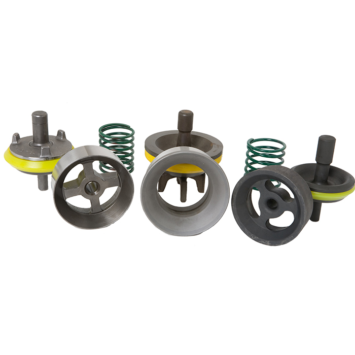
FLUID END EXPENDABLE PUMP PARTSBaker SPD62DOUBLE ANGLE O-RING VALVEThe Double Angle O-ring Valve is made with a tough one-piece body to run more hours between change outs. It"s made withcarburized premium alloy steel to resist wear, provide a positive seal, and help protect against wash out or damage to the pump.FEATURESSpecified for all drilling operations up to and exceeding 5,000 psi Maximum operating temperature is 170F Patented polyurethane insert is noted for its Double Angle 55seal contact surface, which maintains cylinder priming during pump shutdown Sizes fit most mud pumps Shelf life of polyurethane insert is maximum of 5 years Body is a one-piece design, configured to give maximum containment of the insert with minimum use of materialDOUBLE ANGLE O-RING BLUE STREAK HIGH TEMPERATURE VALVEThe High Temperature Double Angle O-ring Valve body is a one-piece design, configured to give maximum containment of the insert with minimum use of material. The valve and insert configuration has been operated at pressures up to and exceeding 5,000 psi. FEATURESMaximum operating temperature is 200FShelf life of polyurethane insert is maximum of 5 yearsSTANDARD PLATE TYPE VALVEThe Standard Plate Type Valve is extremely durable to its premium forged alloy steel body and its unique design. It has been proven by more than 50 years of oilfield service. To prevent dry pistons and liners at startup, the valve features a patented double angle polyurethane insert that maintains cylinder priming during pump shut-down. The precise control of insert pre-load is accomplished with a flat ground insert retaining plate and split retainers. The insert can be replaced in the field with minimum down time. This valve is designed to fit pumps in the oilfield and is used with Baker SPD seats. FEATURESSpecified for all drilling operation up to and exceeding3,500 psiMaximum temperature rating for the standard polyurethane insert is 170FMaximum temperature rating for the Buna-N rubber insert is225FAvailable with Buna-N rubber or polyurethane insertsShelf life of polyurethane insert is maximum of 5 yearsShelf life of Buna-N rubber is maximum of 10 yearsValves with rubber lipless inserts are rated for pressure up to2,500 psiNote: Baker SPD Double Angle O-ring and Standard Plate Type Valves do not interchange with any other manufacturer.Double Angle O-ring Seat, Spring, and ValveDouble Angle O-ring Seat, Spring, and High Temperature ValveStandard Plate Type Seat, Spring, and ValveVALVES AND SEATS 2007 SPD. All rights reserved.4302 Prot, San Antonio, Texas 78219, Tel 1-800-688-5650 or (210)-304-5650, Fax (210) 304-5641Triplex Pump PistonsSPD provides a wide variety of pistons for mud pump appli-cations, including bonded, urethane, rubber, and replaceable rubber or urethane inserts.SPDs bonded urethane pistons are designed for resistance to extrusions and abrasions. With water cooling, these pis-tons will provide optimum performance in oil base mud and high drilling pressures. Bonded urethane pistons are rated for drilling opera-tions up to and exceeding 5,000 psi Urethane pistons provide extended service life under high pressure The Blue Streak
High Temperature Bonded Urethane Triplex PistonTriplex BondedRubber PistonFor more information on liners and other products, please visit us at www.ForumSPD.com or email sales@ForumSPD.com.Zirconia Ceramic Liners HP Design with shoulder on hull to prevent sleeve slippage SPD ID tolerances is +.010/-.000 - Industry allowance is +.015/-.000 Surface nish 4 8 RMS - Chrome sleeved liner nish 16 20 RMS Expected run life exceeding 10,000 hours Hardness: HV 0.3 kg/mm - 1100/1200 (92 94 Rc) (Chrome sleeved liners are 60 64 Rc) Ceramic liners do not create ID ridges which are common in high chrome liners. ID ridges are a cause of piston failures. Ceramic liners improve piston run life. Ceramic liners are pressure rated to pump performance by piston size. Liners are available in sizes 4-1/2 to 7. Liners are available for popular pumps: EMSCO: FC-2200, FB-1300/1600, F-800/1000 Gardner Denver: PX-11, PZ-10/11, PZ-8/9 National: 14-P-200/220, 12-P-160, 10-P-130 Oilwell: A1400/1700PT Wirth: TPK-2200, TPK-1600/2000 Liners for other pump models and liner sizes available upon request.For more information on liners and other products, please visit us at www.ForumSPD.com or email sales@ForumSPD.com. You can also contact us by calling 1-800-688-5650. Zirconia Sleeved Liners for Mud Pumps in Drilling Applications Basic description of Zirconium Oxide/Zirconia: Zirconia engineered ceramic parts can be formed by single axis pressing, isostatic pressing, injection molding, slip casting, or extrusion. Parts can "green machined" to near net size before firing and then "hard" ground using diamond tooling to tolerances less than 0.0002" (0.005 mm). Special grades of zirconia can be enhanced with additives to create a multiphase material and also metallized creating an option to be brazed to metal parts. Applications: Although there are a number of uses for Zirconia, the application of a Zirconia sleeve for a mud pump liner is gaining increasing attention. Although other materials have been used for mud pump liners such as high chromed sleeves and Aluminum Oxide sleeves, Zirconia is gaining favor in this application. A Zirconia sleeve is much harder than a chrome sleeve and therefore offers longer life. Although Ziconia is softer than Alumina, it is not as brittle and therefore will survive low impact shock loading and moderately rough handling. The run life of these two ceramic materials is very close, however because of the careful handling required by Alumina sleeved liners to prevent cracking damage, Zirconia liners are preferred. The Multiphase compound process results in a much smaller grain size which is one of the factors to improve wear life. Properties of Zirconia PSZ MS Grade and Zirconia Multiphase Properties Units Test Temp. Zirconia MS Grade Zirconia Multiphase Density G/cm3 20qC 5.74 5.6-5.7 Flexural Strength MPa 20qC 725 650-800 Tensile Strength MPa 20qC 450 - Weibull Modulus m 20qC >30 >25 Compressive Strength MPa 20qC 1990 1900 Modulus of Elasticity GPa 20qC 205 210-220 Poissons Ratio 20qC 0.31 0.31 Hardness HV0.3 kg/mm2 20qC 1120 1100-1200 Fracture Toughness MPam 20qC 8-12 11-14 Average Grain Size Pm - 40 0.35 - 2 Thermal Conductivity W/m-K 20qC 3.08 2.5 Thermal Expansion Coefficient X 10-6/C 20-400qC 10.2 9.1 Specific Heat J/g-K 20qC 0.47 0.40 Operational Characteristics: Standard chrome sleeve liners wear at a rate of about .007" to .010" on the diameter per 100 hours under normal conditions. When a liner reaches about .070" over nominal diameter the engagement with the piston reduces to a point that blow by begins, resulting in piston failure. The liner wears like a barrel on the ID resulting in the maximum wear at the center of the stroke. The ends of the liner will be at the original nominal diameter. Ceramic sleeve liner will wear in the same way as chrome liners but at a rate of about .001" or less per 100 hours. This rate of wear will result in potential life of 10,000 or more hours. Of course there are a number of variables which would shorten or even lengthen the run time. Recent tests conducted with KCA Duetag and Nabors Drilling have confirmed that wear of only .020 or less have occurred in 4000 hours. Projection of this wear rate would indicate a life of 14,000 hours or more. Urethane pistons are recommended for use with ceramic liners. Piston life in a ceramic liner is variable. The initial piston normally will only run about 200 hours or less. During the initial run the piston further smoothes the liner ID. Subsequent pistons have been known to run much longer up to 500 or 600 hours. However, as the liner becomes worn, the piston lip will begin to loose interference with the liner ID, reducing run life. The above noted run times are dependent on operating conditions. Typical conditions are pressure to 3800 psi, stroke rate to 90 spm, temperature below 170 degrees F, clean mud with weights of 11 to 14 lbs. and a high volume water flush to the back of the piston is required. Higher pressures, stroke rates and temperatures will increase the wear rate.

This depends on the amount of underground pressure. In some instances, a second control well is drilled so that it intercepts the same point where the original wellbore meets the reservoir. Once the new directional well is completed, it can be pumped with kill fluid.
If the well pressure isn’t too severe a relief well can help to release gas so that the original gusher reduces in intensity, allowing it to be controlled. Mud and water are pumped in from a different angle, to get the first well under control and back to proper working order.
Directional drilling software receives input from multiple measurements while drilling (MWD) sensors in the drill bit, and at any branches or junctions. (Other measurement tools include Electromagnetic MWD and Global Positioning Sensors (GPS)). In addition to MWD technology, mud loggers use logging while drilling (LWD) sensors and software. The drill bit has vibration sensors that can detect the type of formation being drilled at any point. Collars can be added along the length of the well, sending back information to the surface regarding torque, weight and bending.
Drill bit sensors can tell the driller about external weight, and rotary speed that can also be used to influence the trajectory. Mud motors can also be used to change direction. With a steerable drill pipe, there’s a bend near the bit. The drillstring stops turning, and then there is plenty of time to use chosen directional techniques to reposition the bit to the desired trajectory. When it starts spinning again, it’ll start going in the direction that it’s now pointing towards. (More about steerable mud motors in the next section).
Mud Motors. Downhole steerable mud motors get positioned near the drill bit, which has a bend in it. What happens is that at the correct depth the drillstring stops rotating, then drilling fluid is pumped through the mud motor so that the drill bit starts to turn just due to the force of the liquid. This mud pressure pushes the drill bit into a different angle, and also begins to bite into the formation at a different angle to the central well trajectory. Once the sensors verify that the drill bit is pointing in the right direction, the drillstring starts to turn again.
Rotary Steerable Systems (RSS). Directional drilling by using the mud motor means that often the drill pipe needs to be slid forward while the drill is motionless. A rotary steerable system can drill and steer at the same time. This means that previously inaccessible formations can be accessed.

Created specifically for drilling equipment inspectors and others in the oil and gas industry, the Oil Rig Mud Pump Inspection app allows you to easily document the status and safety of your oil rigs using just a mobile device. Quickly resolve any damage or needed maintenance with photos and GPS locations and sync to the cloud for easy access. The app is completely customizable to fit your inspection needs and works even without an internet signal.Try Template

CAD blocks: Pumpen HVAC pipes libraries dwg blocks bloques blocos blocchi blocco blocs bl�cke family families symbols details parts models modellen geometry elements entourage cell cells drawing bibliotheque theme category collections content kostenlos insert scale landscaping
Little Beaver offers a wealth of auger options to adapt to varying applications. Solid stem augers are available in 3- to 8-inch diameters and hollow stem augers are available in 6- and 8-inch diameters. The hollow stem augers, which can drill to 60 feet, feature a 2.75- or 3.75-inch internal diameter for collecting samples without the risk of contamination from surrounding soil. The LST1G+HDA’s standard configuration allows for dry auger boring with the use of a solid or hollow stem auger. The drill is also capable of mud rotary boring using an optional mud pump, swivel and bit.


 8613371530291