
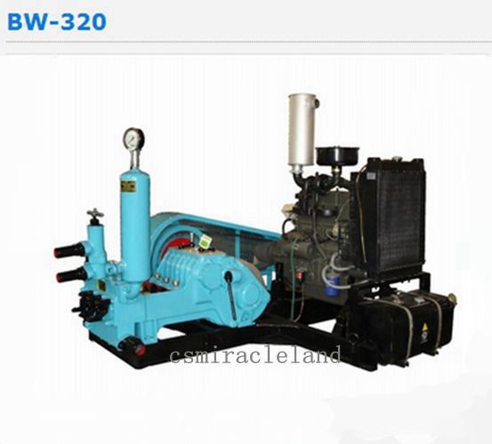
function of mud pump pricelist

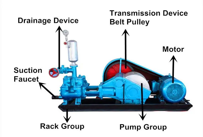
Mud pump, refers to the drilling process to the drilling mud or water and other washing liquid machinery. The main components are volute, impeller, pump seat, pump case, support cylinder, motor seat, motor and other components. Impeller nut is cast iron, so corrosion resistance is good, and convenient processing technology. Pump seat is equipped with four skeleton oil seal and shaft sleeve, prevent shaft wear, prolong the service life of the shaft.
High quality vertical mud pumps with thick, solid shaft and copper motor can be provided in ATO shop. Various models are available, such as 2 inch mud pump, 3 inch mud pump, 4 inch mud pump and 6 inch mud pump. Here is the price list of vertical mud pump.
Sewage mud pump is used in mining, papermaking, printing and dyeing, environmental protection, ceramics, refining, petroleum, chemical industry, farm, dyeing, brewing, food, construction, gold mine, mud, quicksand, mud pond, sewage pond, turbid fluid to send suction thick liquid, loading and suspended matter sewage operation, can also be used for mine drainage and fluid containing mud blocks.
If the mud pump and high-pressure water pump, water gun with the composition of hydraulic mechanized earthwork unit, can be used for land leveling, river and pond dredging, digging and other small water conservancy projects, as well as urban air defense engineering, underground engineering.

A mud pump (sometimes referred to as a mud drilling pump or drilling mud pump), is a reciprocating piston/plunger pump designed to circulate drilling fluid under high pressure (up to 7,500 psi or 52,000 kPa) down the drill string and back up the annulus. A mud pump is an important part of the equipment used for oil well drilling.
Mud pumps can be divided into single-acting pump and double-acting pump according to the completion times of the suction and drainage acting in one cycle of the piston"s reciprocating motion.
Mud pumps come in a variety of sizes and configurations but for the typical petroleum drilling rig, the triplex (three piston/plunger) mud pump is used. Duplex mud pumps (two piston/plungers) have generally been replaced by the triplex pump, but are still common in developing countries. Two later developments are the hex pump with six vertical pistons/plungers, and various quintuplexes with five horizontal piston/plungers. The advantages that these new pumps have over convention triplex pumps is a lower mud noise which assists with better measurement while drilling (MWD) and logging while drilling (LWD) decoding.
The fluid end produces the pumping process with valves, pistons, and liners. Because these components are high-wear items, modern pumps are designed to allow quick replacement of these parts.
To reduce severe vibration caused by the pumping process, these pumps incorporate both a suction and discharge pulsation dampener. These are connected to the inlet and outlet of the fluid end.
The power end converts the rotation of the drive shaft to the reciprocating motion of the pistons. In most cases a crosshead crank gear is used for this.
Displacement is calculated as discharged liters per minute. It is related to the drilling hole diameter and the return speed of drilling fluid from the bottom of the hole, i.e. the larger the diameter of drilling hole, the larger the desired displacement. The return speed of drilling fluid should wash away the debris and rock powder cut by the drill from the bottom of the hole in a timely manner, and reliably carry them to the earth"s surface. When drilling geological core, the speed is generally in range of 0.4 to 1.0 m^3/min.
The pressure of the pump depends on the depth of the drilling hole, the resistance of flushing fluid (drilling fluid) through the channel, as well as the nature of the conveying drilling fluid. The deeper the drilling hole and the greater the pipeline resistance, the higher the pressure needed.
With the changes of drilling hole diameter and depth, the displacement of the pump can be adjusted accordingly. In the mud pump mechanism, the gearbox or hydraulic motor is equipped to adjust its speed and displacement. In order to accurately measure the changes in pressure and displacement, a flow meter and pressure gauge are installed in the mud pump.
The construction department should have a special maintenance worker that is responsible for the maintenance and repair of the machine. Mud pumps and other mechanical equipment should be inspected and maintained on a scheduled and timely basis to find and address problems ahead of time, in order to avoid unscheduled shutdown. The worker should attend to the size of the sediment particles; if large particles are found, the mud pump parts should be checked frequently for wear, to see if they need to be repaired or replaced. The wearing parts for mud pumps include pump casing, bearings, impeller, piston, liner, etc. Advanced anti-wear measures should be adopted to increase the service life of the wearing parts, which can reduce the investment cost of the project, and improve production efficiency. At the same time, wearing parts and other mud pump parts should be repaired rather than replaced when possible.
The crank gear and connecting rods drive a rotary movement that is transferred by the motor transmission. The pressure is produced by the piston in the cylinder due to which the mud is sucked. Following the operation, the suction valve is closed when it moves to left. As the pressure increase in the pipeline, the valve is forced to open and mud is released.
In accordance with the operating liquid displacer type being incorporated, the pumps are subdivided into piston units and plunger-type units. The liquid discharge uniformity is independent of head. The pumping plants are used actively for the processes with the liquids containing solid inclusions in high amounts. Incorporating the self-suction function in piston unit, the liquid is sucked and discharged twice in mud pumps during the single shaft turn, making themselves the double-action pumps whereas, the mud plunger pumps are single-action pumps where the liquid is sucked and discharged only once during a shaft turn.
The single direct-action three-piston pumps prove to be better than other types of drilling. These pumps demonstrate much more uniformity in mud delivery, lesser weight, and easy mounting when compared with two-cylinder units.
Depending on the number of cylinders, the pumping plants are classified into the following categories, single-cylinder, double-cylinder, three-cylinder and multi-cylinder pumping plants. These cylinders may be vertical or horizontal. Comparatively, the multi-cylinder pumping plants will cost higher but don’t feature any significant advantages other than the single-cylinder.
When drilling, there might occur the necessity of mud pumping out- and flushing-out, so there are various types of pumps available for such operations which are required to be installed on drilling rigs.
Sucker-rod pumps: In sucker-rod pumps, the pumpjack is a driver. This pump is installed at the bottom of the well. The reciprocating movements of the pumpjack are converted into liquid flow by the pump, which results in delivery of liquid on the surface. These pumps move oil with various admixtures demonstrating high level of capacity.
Screw pumps:The screw pumps are small-sized and are generally used to deliver mud into a centrifuge. These pumps have the rotor and stator as the major structural components and the material used to manufacture these components suit right for smooth pumping of liquids with solid inclusions and high level of viscosity. The pumped liquid flows with stable pressure, shaft slowly and the flow is free of vortexes. These pumps comparatively require minimum service.
Well pumps: These pumps are submerged into wells. The ground part of the plant is a transformer substation equipped for start and adjustment. The pump has a vertical structure, with a fixed cylinder and single-action. A plunger and valve are moving parts. The pumped liquid may contain water content of up to 99% at the temperature as high as 130ºC.
All the mud pumps have few general advantages that include the capability to process liquids and substances with high level of viscosity and with admixtures. Also, enabling the smooth flow of substances, free of pulsations or suspensions mixing are counted under the major advantages of incorporating mud pumps. The pumps have high suction power and small weight, easing out the transportation and installation at remote oil fields. They are highly reliable and also affordable.
There are various types of mud pumps available for different purposes. So, it is important to incorporate the right one for your purpose. A Professional help in getting the right mud pump would be a good and safe option.

The 2,200-hp mud pump for offshore applications is a single-acting reciprocating triplex mud pump designed for high fluid flow rates, even at low operating speeds, and with a long stroke design. These features reduce the number of load reversals in critical components and increase the life of fluid end parts.
The pump’s critical components are strategically placed to make maintenance and inspection far easier and safer. The two-piece, quick-release piston rod lets you remove the piston without disturbing the liner, minimizing downtime when you’re replacing fluid parts.

A mud pump is a reciprocating piston or plunger device designed to pump drilling fluid under high pressures and volumes down the drill string of a drilling rig. The main functions of drilling fluid are to provide hydrostatic pressure to prevent formation fluids from entering and to stabilize the bore, to keep the drill bit cool and clean, to carry drill cuttings back out to the surface, and to suspend the drill cuttings while drilling is paused or during the pullback process.
Mud pumps consist of two main sub-assemblies- the fluid end and the power end. The fluid end performs the pumping process with valves, pistons, and liners, or plungers and stuffing boxes- depending upon the type used. These components are considered expendables, and are designed to be easily replaced in the field. The power end contains the eccentric or crankshaft, along with the connecting rods, and cross heads/slides.
Tulsa Triplex is a Tulsa Rig Iron company. We manufacture pumps from 100 to 600 horsepower that are designed to be easily maintained and are capable of being completely rebuilt. Our pumps feature a smaller footprint and lighter weight than competing models, making them completely legal load size and weight in most instances. They are available as a bare pump, with chainbox, or a complete skidded package.

A mud pump is a reciprocating piston/plunger pump designed to circulate drilling fluid under high pressure (up to 7,500 psi (52,000 kPa)) down the drill string and back up the annulus. A duplex mud pump is an important part of the equipment used for oil well drilling.
Duplex mud pumps (two piston/plungers) have generally been replaced by the triplex pump, but are still common in developing countries. Two later developments are the hex pump with six vertical pistons/plungers, and various quintuplex’s with five horizontal piston/plungers. The advantages that Duplex mud pumps have over convention triplex pumps is a lower mud noise which assists with better Measurement while drilling and Logging while drilling decoding.
Use duplex mud pumps to make sure that the circulation of the mud being drilled or the supply of liquid reaches the bottom of the well from the mud cleaning system. Despite being older technology than the triplex mud pump, the duplex mud pumps can use either electricity or diesel, and maintenance is easy due to their binocular floating seals and safety valves.
A mud pump is composed of many parts including mud pump liner, mud pump piston, modules, hydraulic seat pullers, and other parts. Parts of a mud pump:housing itself
Duplex pumps are used to provide a secondary means of fuel transfer in the event of a failure of the primary pump. Each pump in a duplex set is sized to meet the full flow requirements of the system. Pump controllers can be set for any of the following common operating modes:Lead / Lag (Primary / Secondary): The lead (primary) pump is selected by the user and the lag (secondary pump operates when a failure of the primary pump is detected.
Alternating: Operates per Lead / Lag (Primary / Secondary) except that the operating pump and lead / lag status alternate on consecutive starts. A variation is to alternate the pumps based on the operating time (hour meter) of the lead pump.

Positive displacements pumps are generally used on drilling rigs to pump high pressure and high volume of drilling fluids throughout a drilling system. There are several reasons why the positive displacement mud pumps are used on the rigs.
The duplex pumps (Figure 1) have two cylinders with double acting. It means that pistons move back and take in drilling mud through open intake valve and other sides of the same pistons, the pistons push mud out through the discharge valves.
When the piston rod is moved forward, one of intake valves is lift to allow fluid to come in and one of the discharge valve is pushed up therefore the drilling mud is pumped out of the pump (Figure 2).
On the other hand, when the piston rod is moved backward drilling fluid is still pumped. The other intake and discharge valve will be opened (Figure 3).
The triplex pumps have three cylinders with single acting. The pistons are moved back and pull in drilling mud through open intake valves. When the pistons are moved forward and the drilling fluid is pushed out through open discharge valves.
On the contrary when the piston rods are moved backward, the intake valve are opened allowing drilling fluid coming into the pump (Figure 6). This video below shows how a triplex mud pump works.
Because each pump has power rating limit as 1600 hp, this will limit capability of pump. It means that you cannot pump at high rate and high pressure over what the pump can do. Use of a small liner will increase discharge pressure however the flow rate is reduces. Conversely, if a bigger liner is used to deliver more flow rate, maximum pump pressure will decrease.
As you can see, you can have 7500 psi with 4.5” liner but the maximum flow rate is only 297 GPM. If the biggest size of liner (7.25”) is used, the pump pressure is only 3200 psi.
Finally, we hope that this article would give you more understanding about the general idea of drilling mud pumps. Please feel free to add more comments.

Mud pump is one of the most critical equipment on the rig; therefore personnel on the rig must have good understanding about it. We’ve tried to find the good training about it but it is very difficult to find until we’ve seen this VDO training and it is a fantastic VDO training about the basic of mud pumps used in the oilfield. Total length of this VDO is about thirteen minutes and it is worth to watch it. You will learn about it so quickly. Additionally, we also add the full detailed transcripts which will acceleate the learning curve of learners.
Powerful mud pumps pick up mud from the suction tank and circulate the mud down hole, out the bit and back to the surface. Although rigs usually have two mud pumps and sometimes three or four, normally they use only one at a time. The others are mainly used as backup just in case one fails. Sometimes however the rig crew may compound the pumps, that is, they may use three or four pumps at the same time to move large volumes of mud when required.
Rigs use one of two types of mud pumps, Triplex pumps or Duplex pumps. Triplex pumps have three pistons that move back-and-forth in liners. Duplex pumps have two pistons move back and forth in liners.
Triplex pumps have many advantages they weight 30% less than a duplex of equal horsepower or kilowatts. The lighter weight parts are easier to handle and therefore easier to maintain. The other advantages include;
• One of the more important advantages of triplex over duplex pumps, is that they can move large volumes of mud at the higher pressure is required for modern deep hole drilling.
Triplex pumps are gradually phasing out duplex units. In a triplex pump, the pistons discharge mud only when they move forward in the liner. Then, when they moved back they draw in mud on the same side of the piston. Because of this, they are also called “single acting.” Single acting triplex pumps, pump mud at a relatively high speeds. Input horsepower ranges from 220 to 2200 or 164 to 1641 kW. Large pumps can pump over 1100 gallons per minute, over 4000 L per minute. Some big pumps have a maximum rated pressure of over 7000 psi over 50,000 kPa with 5 inch/127 mm liners.
Here is a schematic of a triplex pump. It has three pistons each moving in its own liner. It also has three intake valves and three discharge valves. It also has a pulsation dampener in the discharge line.
Look at the piston at left, it has just completed pushing mud out of the liner through the open discharge valve. The piston is at its maximum point of forward travel. The other two pistons are at other positions in their travel and are also pumping mud. But for now, concentrate on the left one to understand how the pump works. The left piston has completed its backstroke drawing in mud through the open intake valve. As the piston moved back it instead of the intake valve off its seat and drew mud in. A strong spring holds the discharge above closed. The left piston has moved forward pushing mud through the now open discharge valve. A strong spring holds the intake valve closed. They left piston has completed its forward stroke they form the length of the liner completely discharging the mud from it. All three pistons work together to keep a continuous flow of mud coming into and out of the pump.
Crewmembers can change the liners and pistons. Not only can they replace worn out ones, they can also install different sizes. Generally they use large liners and pistons when the pump needs to move large volumes of mud at relatively low pressure. They use a small liners and pistons when the pump needs to move smaller volumes of mud at a relatively high pressure.
In a duplex pump, pistons discharge mud on one side of the piston and at the same time, take in mud on the other side. Notice the top piston and the liner. As the piston moves forward, it discharges mud on one side as it draws in mud on the other then as it moves back, it discharges mud on the other side and draws in mud on the side it at had earlier discharge it. Duplex pumps are therefore double acting.
Double acting pumps move more mud on a single stroke than a triplex. However, because of they are double acting they have a seal around the piston rod. This seal keeps them from moving as fast as a triplex. Input horsepower ranges from 190 to 1790 hp or from 142 to 1335 kW. The largest pumps maximum rated working pressure is about 5000 psi, almost 35,000 kPa with 6 inch/152 mm linings.
A mud pump has a fluid end, our end and intake and the discharge valves. The fluid end of the pump contains the pistons with liners which take in or discharge the fluid or mud. The pump pistons draw in mud through the intake valves and push mud out through the discharge valves.
The power end houses the large crankshaft and gear assembly that moves the piston assemblies on the fluid end. Pumps are powered by a pump motor. Large modern diesel/electric rigs use powerful electric motors to drive the pump. Mechanical rigs use chain drives or power bands (belts) from the rig’s engines and compounds to drive the pump.
A pulsation dampener connected to the pump’s discharge line smooths out surges created by the pistons as they discharge mud. This is a standard bladder type dampener. The bladder and the dampener body, separates pressurized nitrogen gas above from mud below. The bladder is made from synthetic rubber and is flexible. When mud discharge pressure presses against the bottom of the bladder, nitrogen pressure above the bladder resists it. This resistance smoothes out the surges of mud leaving the pump.
Here is the latest type of pulsation dampener, it does not have a bladder. It is a sphere about 4 feet or 1.2 m in diameter. It is built into the mud pump’s discharge line. The large chamber is form of mud. It has no moving parts so it does not need maintenance. The mud in the large volume sphere, absorbs this surges of mud leaving the pump.
A suction dampener smooths out the flow of mud entering into the pump. Crewmembers mount it on the triplex mud pump’s suction line. Inside the steel chamber is a air charged rubber bladder or diaphragm. The crew charges of the bladder about 10 to 15 psi/50 to 100 kPa. The suction dampener absorbs surges in the mud pump’s suction line caused by the fast-moving pump pistons. The pistons, constantly starts and stops the mud’s flow through the pump. At the other end of the charging line a suction pumps sends a smooth flow of mud to the pump’s intake. When the smooth flow meets the surging flow, the impact is absorbed by the dampener.
Workers always install a discharge pressure relief valve. They install it on the pump’s discharge side in or near the discharge line. If for some reason too much pressure builds up in the discharge line, perhaps the drill bit or annulus gets plugged, the relief valve opens. That opened above protects the mud pump and system damage from over pressure.
Some rig owners install a suction line relief valve. They install it on top of the suction line near the suction dampener. They mount it on top so that it won’t clog up with mud when the system is shut down. A suction relief valve protects the charging pump and the suction line dampener. A suction relief valve usually has a 2 inch or 50 mm seat opening. The installer normally adjusts it to 70 psi or 500 kPa relieving pressure. If both the suction and the discharged valves failed on the same side of the pump, high back flow or a pressure surge would occur. The high backflow could damage the charging pump or the suction line dampener. The discharge line is a high-pressure line through which the pump moves mud. From the discharge line, the mud goes through the stand pipe and rotary hose to the drill string equipment.

The drilling industry has roots dating back to the Han Dynasty in China. Improvements in rig power and equipment design have allowed for many advances in the way crude oil and natural gas are extracted from the ground. Diesel/electric oil drilling rigs can now drill wells more than 4 miles in depth. Drilling fluid, also called drilling mud, is used to help transfer the dirt or drill cuttings from the action of the drilling bit back to the surface for disposal. Drill cuttings can vary in shape and size depending on the formation or design of the drill bit used in the process.
Watch the video below to see how the EDDY Pump outperforms traditional pumps when it comes to high solids and high viscosity materials commonly found on oil rigs.
Solids control equipment including shakers, hydro-cyclones, and centrifuges are utilized to clean the drill cuttings from the drilling fluid, which then allows it to be reused and recirculated. The circuit includes the mixing of the drilling fluid in the rig tanks.
The drilling fluid is prepared to control fluid loss to the formation by the addition of chemicals or mineral agents. Commercial barite or other weighting agents are added to control the hydrostatic pressure exuded on the bottom of the well which controls formation pressures preventing fluid or gas intrusion into the wellbore.
The fluid is charged into high-pressure mud pumps which pump the drilling mud down the drill string and out through the bit nozzles cleaning the hole and lubricating the drill bit so the bit can cut efficiently through the formation. The bit is cooled by the fluid and moves up the space between the pipe and the hole which is called the annulus. The fluid imparts a thin, tough layer on the inside of the hole to protect against fluid loss which can cause differential sticking.
The fluid rises through the blowout preventers and down the flowline to the shale shakers. Shale shakers are equipped with fine screens that separate drill cutting particles as fine as 50-74 microns. Table salt is around 100 microns, so these are fine cuttings that are deposited into the half-round or cuttings catch tank. The drilling fluid is further cleaned with the hydro-cyclones and centrifuges and is pumped back to the mixing area of the mud tanks where the process repeats.
The drill cuttings contain a layer of drilling fluid on the surface of the cuttings. As the size of the drill cuttings gets smaller the surface area expands exponentially which can cause rheological property problems with the fluid. The fluid will dehydrate and may become too thick or viscous to pump so solids control and dilution are important to the entire drilling process.
One of the most expensive and troubling issues with drilling operations is the handling, processing, and circulation of drilling mud along with disposing of the unwanted drill cuttings. The drilling cuttings deposited in the half round tank and are typically removed with an excavator that must move the contents of the waste bin or roll-off box. The excavators are usually rented for this duty and the equipment charges can range from $200-300/day. Add in the cost for the day and night manpower and the real cost for a single excavator can be as much as $1800/day.
Using the excavator method explained above, the unloading of 50 barrels of drill cuttings from the half round can take as long as two hours. This task is mostly performed by the solids control technicians. The prime duty for the solids control technicians is to maintain the solids control equipment in good working order. This involves maintenance for the equipment, screen monitoring and changing, centrifuge adjustments, and retort testing to prepare a daily operational summary of the solids control program.
One solids control company reported the idle time for the excavator can be more than 8 hours for a 24-hour period with 8 hours of operation and 8 hours of shut down time. Fuel and time lost can cause an economic drag on rig operations. And lastly, there have been several accidents on each rig causing a potential for injury, loss of production, and lost revenue as the excavator must be repaired.
Offshore drilling rigs follow a similar process in which the mud is loaded into empty drums and held on the oil platform. When a certain number of filled drums is met, the drums are then loaded onto barges or vessels which take the drilling mud to the shore to unload and dispose of.
Oil field drilling operations produce a tremendous volume of drill cuttings that need both removal and management. In most cases, the site managers also need to separate the cuttings from the drilling fluids so they can reuse the fluids. Storing the cuttings provides a free source of stable fill material for finished wells, while other companies choose to send them off to specialty landfills. Regardless of the final destination or use for the cuttings, drilling and dredging operations must have the right high solids slurry pumps to move them for transport, storage, or on-site processing. Exploring the differences in the various drilling fluids, cutting complications, and processing options will reveal why the EDDY Pump is the best fit for the job.
The Eddy Pump is designed to move slurry with solid content as high as 70-80 % depending on the material. This is an ideal application for pumping drill cuttings. Drill cuttings from the primary shakers are typically 50% solids and 50% liquids. The Eddy Pump moves these fluids efficiently and because of the large volute chamber and the design of the geometric rotor, there is very little wear on the pump, ensuring long life and greatly reduced maintenance cost for the lifetime of the pump.
plumbed to sweep the bottom of the collection tank and the pump is recessed into a sump allowing for a relatively clean tank when the solids are removed. The Eddy Pump is sized to load a roll-off box in 10-12 minutes. The benefit is cuttings handling is quicker, easier, safer, and allows for pre-planning loading where the labor of the solids control technician is not monopolized by loading cuttings. Here, in the below image, we’re loading 4 waste roll-off bins which will allow the safe removal of cuttings without fear of the half-round catch tank running over.
Mud cleaning systems such as mud shaker pumps and bentonite slurry pumps move the material over screens and through dryers and centrifuges to retrieve even the finest bits of stone and silt. However, the pump operators must still get the raw slurry to the drill cuttings treatment area with a power main pump. Slurry pumps designed around the power of an Eddy current offer the best performance for transferring cuttings throughout a treatment system.
Options vary depending on whether the company plans to handle drill cuttings treatment on-site or transport the materials to a remote landfill or processing facility. If the plan is to deposit the cuttings in a landfill or a long-term storage container, it’s best to invest in a pump capable of depositing the material directly into transport vehicles. Most dredging operations rely on multiple expensive vacuum trucks, secondary pumps, and extra pieces of equipment.
Using an EDDY Pump will allow a project to eliminate the need for excavators/operators to load drill cuttings, substantially lowering both labor and heavy equipment costs. The EDDY Pump also allows a company to eliminate vacuum trucks once used for cleaning the mud system for displacing fluids. Since the pump transfers muds of all types at constant pressure and velocity throughout a system of practically any size, there’s little need for extra equipment for manual transfer or clean up on the dredge site.
The EDDY Pump can fill up a truck in only 10 minutes (compared to an hour) by using a mechanical means such as an excavator. For this reason, most companies can afford one piece of equipment that can replace half a dozen other units.
This application for the Eddy Pump has the potential to revolutionize the drilling industry. Moving the excavator out of the “back yard” (the area behind the rig from the living quarters) will make cuttings handling a breeze. Trucking can be easier scheduled during daylight hours saving on overtime and incidences of fatigued driving. Rig-site forklifts can move the roll-off boxes out of the staging area and into the pump loading area. The operator can save money on excavators rental, damages, and keep the technician operating the solids control equipment.
The EDDY Pump is ideal for drilling mud pump applications and can be connected directly onto the drilling rigs to pump the drilling mud at distances over a mile for disposal. This eliminates the need for costly vacuum trucks and also the manpower needed to mechanically move the drilling mud. The reasons why the EDDY Pump is capable of moving the drilling mud is due to the hydrodynamic principle that the pump creates, which is similar to the EDDY current of a tornado. This tornado motion allows for the higher viscosity and specific gravity pumping ability. This along with the large tolerance between the volute and the rotor allows for large objects like rock cuttings to pass through the pump without obstruction. The large tolerance of the EDDY Pump also enables the pump to last many times longer than centrifugal pumps without the need for extended downtime or replacement parts. The EDDY Pump is the lowest total life cycle pump on the market.

AfghanistanAlbaniaAlgeriaAmerican SamoaAndorraAngolaAnguillaAntarcticaAntigua and BarbudaArgentinaArmeniaArubaAustraliaAustriaAzerbaijanBahamasBahrainBangladeshBarbadosBelarusBelgiumBelizeBeninBermudaBhutanBoliviaBonaire, Sint Eustatius and SabaBosnia and HerzegovinaBotswanaBouvet IslandBrazilBritish Indian Ocean TerritoryBrunei DarussalamBulgariaBurkina FasoBurundiCabo VerdeCambodiaCameroonCanadaCayman IslandsCentral African RepublicChadChileChinaChristmas IslandCocos IslandsColombiaComorosCongoCongo, Democratic Republic of theCook IslandsCosta RicaCroatiaCubaCuraçaoCyprusCzechiaCôte d"IvoireDenmarkDjiboutiDominicaDominican RepublicEcuadorEgyptEl SalvadorEquatorial GuineaEritreaEstoniaEswatiniEthiopiaFalkland IslandsFaroe IslandsFijiFinlandFranceFrench GuianaFrench PolynesiaFrench Southern TerritoriesGabonGambiaGeorgiaGermanyGhanaGibraltarGreeceGreenlandGrenadaGuadeloupeGuamGuatemalaGuernseyGuineaGuinea-BissauGuyanaHaitiHeard Island and McDonald IslandsHoly SeeHondurasHong KongHungaryIcelandIndiaIndonesiaIranIraqIrelandIsle of ManIsraelItalyJamaicaJapanJerseyJordanKazakhstanKenyaKiribatiKorea, Democratic People"s Republic ofKorea, Republic ofKuwaitKyrgyzstanLao People"s Democratic RepublicLatviaLebanonLesothoLiberiaLibyaLiechtensteinLithuaniaLuxembourgMacaoMadagascarMalawiMalaysiaMaldivesMaliMaltaMarshall IslandsMartiniqueMauritaniaMauritiusMayotteMexicoMicronesiaMoldovaMonacoMongoliaMontenegroMontserratMoroccoMozambiqueMyanmarNamibiaNauruNepalNetherlandsNew CaledoniaNew ZealandNicaraguaNigerNigeriaNiueNorfolk IslandNorth MacedoniaNorthern Mariana IslandsNorwayOmanPakistanPalauPalestine, State ofPanamaPapua New GuineaParaguayPeruPhilippinesPitcairnPolandPortugalPuerto RicoQatarRomaniaRussian FederationRwandaRéunionSaint BarthélemySaint Helena, Ascension and Tristan da CunhaSaint Kitts and NevisSaint LuciaSaint MartinSaint Pierre and MiquelonSaint Vincent and the GrenadinesSamoaSan MarinoSao Tome and PrincipeSaudi ArabiaSenegalSerbiaSeychellesSierra LeoneSingaporeSint MaartenSlovakiaSloveniaSolomon IslandsSomaliaSouth AfricaSouth Georgia and the South Sandwich IslandsSouth SudanSpainSri LankaSudanSurinameSvalbard and Jan MayenSwedenSwitzerlandSyria Arab RepublicTaiwanTajikistanTanzania, the United Republic ofThailandTimor-LesteTogoTokelauTongaTrinidad and TobagoTunisiaTurkmenistanTurks and Caicos IslandsTuvaluTürkiyeUS Minor Outlying IslandsUgandaUkraineUnited Arab EmiratesUnited KingdomUnited StatesUruguayUzbekistanVanuatuVenezuelaViet NamVirgin Islands, BritishVirgin Islands, U.S.Wallis and FutunaWestern SaharaYemenZambiaZimbabweÅland Islands

Mud pump is mainly used for geological drilling, geological engineering construction and foundation treatment of low and medium pressure grouting pump, etc. Mud pump is a machine that sends mud or water to the borehole during the drilling process. Mud pump is an important part of drilling equipment. All major businesses have mud pump parts for sale.
The main function of mud pump is to inject mud into the well along with the bit during the drilling process. It plays the role of cooling the drill bit, cleaning the drilling tool, fixing the well wall, driving drilling, and bringing the cuttings back to the surface after drilling.
In the commonly used positive circulation drilling, the mud pump sends the surface flushing medium-- clean water, mud or polymer flushing fluid to the end of the drill bit through the high pressure hose faucet and the center hole of the drill string under a certain pressure. Therefore, the purpose of cooling the drill bit and removing and conveying the cuttings to the surface is achieved.
Petroleum drilling mud pump is a kind of volumetric mud pump. Its basic working principle is that the volume of the sealed working chamber (mud pump cylinder liner) is periodically changed to convert the original mechanical energy into the pressure energy of the liquid to complete the operation.
The specific process relies on the reciprocating motion of the mud pump piston in the cylinder liner to make the volume of the working chamber in the cylinder liner change periodically. The mud pump cylinder liner is isolated from the outside world by means of a sealing device such as a seal ring, and communicates or closes with the pipeline through the pump valve (suction valve or discharge valve), which shows the importance of the mud pump cylinder liner. The three-cylinder mud pumps currently on the market are equipped with three cylinder sleeves.

Within the petroleum industry centrifugal pumps are necessary in order to process fluids especially hydrocarbons. Another important application within the petroleum industry is in the mud circuit on a drilling rig. On drilling rigs, mud which consists mainly of water and bentonite as well as of several different additives depending on many different factors is used. The heart of the mud circuit is the mud pump which is in general a high pressure piston pump. It provides the major part of head to overcome the system’s resistance. The mud is pumped through a piping system to the derrick and through the standpipe to a definite high. Now through the kelly hose via the gooseneck into the upper kelly cock. It flows through the Kelly and the lower kelly cock into the drill string down the borehole. At its end, the mud leaves the drilling collars through the drilling bit.
1. Select a pump to handle the highest anticipated flow. Select an impellersize to provide sufficient discharge head to overcome friction in the lines,lift the fluid as required, and have sufficient head remaining to operatethe equipment being fed.
Initially this guideline suggested that the pump flange size be selected to provide the highest anticipated flow, even though the flange size has nothing to do with the flow rate. Most pump curves are listed in terms of the flange sizes. The size of the pump impeller housing increases as the flange size increases. An impeller rotating at constant speed will create a constant head independent of the size of the housing or the flanges. An impeller that fits inside a 2×3, 3×4, 4×5, or 5×6 pump will produce the same head in each pump if it is rotated at the same speed. Because the housing of a pump with a 2-inch and 3-inch flange is smaller, the internal friction at a high flow rate will be greater than a 56 pump. This means that the capacity of the various pump sizes will be indicated by their flange sizes. The committee decided to only indicate that the pump should be selected to handle the highest anticipated flow rate, instead of indicating that the flange size is commonly used to specify pump size.
2.Install the centrifugal pump with a flooded suction that is sumped so thatsufficient submergence is available to prevent vortexing or air-locking.Foot valves are not needed or recommended with flooded suctions.
A small influx of air into the suction of a centrifugal pump can create cavitation problems and diminished flow. As the air enters the chamber with the impeller, it tends to concentrate in the center of the impeller because of the centripetal acceleration of the drilling fluid.
The liquid continues to move through the pump. The air does not always continue to the impeller tip, but tends to remain in the center of the impeller. This bubble of air forms a barrier for the incoming fluid, which diminishes the flow rate into the pump. The air also experiences a significant decrease in pressure—possibly even below atmospheric pressure. This causes implosions of vapor bubbles that can remove metal from the impeller. The pump will sound as if it is pumping gravel. If it continues in this mode for a long period of time, the impeller will be severely damaged.
Flooded suctions tend to eliminate most of the air influx problems but sometimes a small vortex will form in the mud tank. These small vortexes can entrain a significant amount of area. Increasing agitation in the tanks may prevent a coherent cylinder of air from reaching the suction line. Alternatively, a plate can be installed in the tank to interrupt the formation of a vortex.
In some cases, a centrifugal pump is placed on the ground above a pond or buried tank. Foot valves are needed if the centrifugal pump is operated above the liquid level of the suction tank. Foot valves are check valves that prevent the suction line from draining when the pump is turned off. Care must be taken to eliminate tiny air leaks in the suction line because the absolute pressure will be below atmospheric pressure. The pump and suction line should be filled with fluid before the pump motor is started. Centrifugal pumps do not move air very well.
A centrifugal pump suction can only lift fluid a certain height above a liquid level. These heights are determined by observing the NPSH (negative pressure suction head) values listed on the centrifugal pump curves. If the NPSH is exceeded, cavitation can destroy the impeller.
3. Install a removable screen over the suction to keep out large solids andtrash. It can be made out of half-inch expanded metal and should have atotal screen area at least five times the cross-sectional area of thesuction line so it will not restrict flow. An extended handle arrangementreaching to the tank surface is desirable to allow the screen to be pulledduring service and cleaned.
An expanded metal screen prevents objects (such as gloves, buckets, pieces of clothing, chunks of rubber, etc.) from plugging the suction line or fouling the impeller. A bucket, turned so that the bottom fits into the suction line, can be difficult to diagnose and locate. A box made from expanded metal that covers the suction can prevent these disasters. If two alignment yokes are welded to the tank walls to hold a 1-inch pipe handle, the screen can be removed, cleaned, and easily returned to the suction opening. Without these alignment yokes, reseating the expanded metal box is difficult.
4. Suction and discharge lines should be properly sized and as short aspractical. Flow velocities should be in the range of 5 to 10 ft/sec. Lessthan 5 ft/sec causes solids to form a tight layer obstructing the bottomof horizontal lines. At velocities at or exceeding 10 ft/sec, pipe-turnstend to erode, headers do not distribute properly, and usually there willbe cavitation in the suction lines. To calculate the velocity inside thepipe, use the following equation:
Horizontal pipes will fill with solids until the flow rate reaches 5 ft/sec. Barite in equalizing lines between mud tanks is normally settled until the velocity between the tanks reaches 5 ft/sec. Increasing the diameter of connection lines only causes more barite to settle. Above 10 ft/sec, pressure losses in the pipe become too great. Elbows and swages tend to cause turbulence in the flow stream, which can lead to cavitation.
5. Eliminate manifolding. One suction and one discharge per pump ismost cost effective over time. Do not manifold two pumps on the samesuction line. Do not pump into the same discharge line with two or morepumps.
Flexibility of piping so fluid can be pumped from any tank through any equipment to any other tank has created more problems over the years than just about any other concept. A properly plumbed system should require only one suction and one discharge for each piece of solids-removal equipment. Ignoring this rule allows rig hands the opportunity to open or close the wrong valves. A leaky or incorrectly opened valve can reduce drilled-solids removal efficiency by up to 50%. This translates to an expensive drilling-fluid system. This problem can be eliminated by storing an extra pump and motor. Arrange the centrifugal pumps and motors so that they may be easily replaced. If a pump or motor fails, simply replace the unit. The damaged unit can be replaced during routine maintenance. Two centrifugal pumps in parallel will not double the head available to equipment because a centrifugal pump is a constant head device. For example, visualize a standpipe that is constantly filled with fluid. If two standpipes of approximately the same height are connected, the flow from both pipes will almost equal the flow from one standpipe. If fluid stands lower in one standpipe than the other. fluid will flow from the highest standpipe to the lowest standpipe. This same flow occurs when two pumps are connected in parallel—fluid will flow backward through one of the pumps.
6. Install a pressure gauge between the pump discharge and the first valve.When the valve is closed briefly, the pressure reading may be used fordiagnostic evaluation of the pump performance.
A centrifugal pump uses the smallest amount of power when no fluid is moving through the pump (that is, when the discharge valve is completely closed). If the valve remains closed for longer than 5 minutes, the fluid within the pump will become hot from the impeller agitation. This hot fluid may damage the seals. Closing the valve for a short time allows a good reading of the no-flow head produced by the pump. This reading should be compared with the pump manufacturer’s charts. The diameter of the impeller can then be determined. (A pump may be stamped 5X6X14. This means that it could house a 14-inch impeller but it does not mean that it has a 14-inch impeller. The impeller size is adjusted so the pump will deliver the proper head.) After the pump has been in service for a period of time, the pressure reading will assess the condition of the impeller. This eliminates the need to dismantle the pump for inspection. If the manifold pressure is incorrect, reading the pump no-flow discharge head will assist in troubleshooting.
7.Keep air out of the pump by degassing the mud, having adequate suctionline submergence, and installing baffles to break mixer vortices. Properly sized, baffled, and agitated compartments will not vortexunless the drilling fluid level becomes extremely low.
Centrifugal pumps cannot pump aerated fluid. The air tends to gravitate toward the center of the impeller while the liquid moves toward the outside. This creates an air bubble at the center of the impeller. When the air bubble becomes as large as the suction line diameter, fluid will no longer enter the pump. This is called airlock. Only a small cylinder of air vortexing into the pump is sufficient to prevent the pump form moving liquid. Since the air accumulates over a period of time, a small vortex the size of a pencil is sufficient to eventually shut down a 6×8 pump. Baffles are inexpensive and easily installed in an empty tank. Any vertical surface that disrupts the swirling motion of the fluid in a compartment is usually sufficient to destroy a vortex. Rig pump efficiency can decrease from 99 to 85% efficiency if the drilling fluid content rises to 6% volume. Air in the drilling fluid may be calculated by measuring the pressurized and unpressurized mud weight.
8. Do not restrict the flow to the suction side of the pump. Starving thepump suction causes cavitation and this will rapidly damage the pump.When a pump begins cavitating, small vacuum bubbles adjacent to the impeller surface start imploding. The pump sounds as if it is pumping gravel. The implosions quickly remove metal from the surface to the impeller blade. In a very short period of time, holes will appear in the metal. Important: Do not close a valve on the suction line while the pump is running!
Starving the suction will decrease the output head. If the head, or pressure produced by the pump, is too high, change to a smaller diameter impeller. On a temporary basis, a discharge valve can be partially closed. On a long-term basis, however, considerable valve erosion will occur so a new, properly sized impeller is necessary. Even a large centrifugal pump is not damaged if only 10 to 20 gpm is discharged from the pump. In fact, the lower flow rates will require less horsepower to the motor than pumping fluid at a much higher flow rate.
Centrifugal pumps will pump fluid even if running in reverse. The head produced by the pump will be lower than it should be. The pressure gauge installed between the pump and the first valve will assist with the diagnosis. Usually, switching two wires in the lead-in panel box will correct the rotation.
10.Startup procedure for an electric motor–driven centrifugal pump with avalve on the discharge side between the pump and the equipment beingoperated is to start the pump with the valve just slightly open. Once thepump is up to speed, open the valves slowly to full open. This approachwill reduce the startup load on the electric motor and will reduce theshock loading on equipment such as pressure gauges and hydrocyclones.
An alternative startup procedure is to completely close thedischarge valve before startup and then open the valve slowly immediatelyafter startup to prevent overheating and possible damage to thepump seals.
An electric motor–driven centrifugal pump will immediately try to produce a constant head when it is turned on. If the pump is pumping into an empty line, the flow rate is enormous. Very high flow rates require very high currents to the electric motor. Circuit breakers can stop the pump and avoid motor burnout. Lower horsepower is required if the pump is started with the discharge valve closed.
Function: Mud Pump Liner also called the cylinder liner. The cylinder liner is the core accessory of the mud pump, which has the functions of storing mud, bearing pressure and completing the suction and discharge of mud. Because the cylinder liner is in direct contact with the mud, it is easy to be worn and corroded by the tiny sand particles, acid and alkali liquid in the mud during work. As a result, the inner diameter of the cylinder liner becomes larger, leakage occurs in the seal between the cylinder liner and the piston, and the pressure is reduced. The cylinder liner is scrapped eventually. Cylinder liner is a one-time wearable part that cannot be reused, and its life span directly affects the normal operation and cost of the drilling operation.
Bimetal Liners are also known as double metal liners. Forged steel pipe 45# (ASTM1045) is used for the outer sleeve, the normalizing hardness: 160BHN (HB180-200); elongation: 17%; tensile strength is not less than 85000PSI; yield strength is not less than 60000 PSI; The inner sleeve material is high chromium wear-resistant cast iron, with chromium content of 26-28%; thickness is 0.25 to 0.35 inches (6.35-8.89 mm), and the standard thickness is 7 mm. Usually, the service life is 800 hours under normal drilling conditions.
The inner liner is made of zirconia or aluminium oxide, and the outer sleeve is made of 45# (ASTM1045) forged steel. It has the advantages of more wear resistance, corrosion resistance, high-pressure resistance, high-temperature resistance, high strength and high hardness than metal cylinder liners. The service life is more than 4000 hours under normal drilling conditions.
The piston assembly is one of the main parts of the hydraulic end system of the mud pump, and it is also one of the vulnerable parts of the drilling work. The discharge pressure of the mud pump is generated by the reciprocating linear movement of the piston assembly in the piston.
The piston assembly is composed of piston hub, rubber, snap ring, plate, etc. The material of the piston hub is 42CrMo (ASTM4140), and the material of the piston rubber is NBR rubber or Polyurethane Rubber.
Polyurethane rubber has excellent oil resistance and wear resistance. The working temperature is not higher than 120℃, which is suitable for oil-based mud with working pressure below 35Mpa and working environment with high sand content.
Lake Petro has over 10 years of experience in Liners and Pistons, we export a large amount of mud pump parts to many countries and regions in the world. If you are interested in any of our products, please contact sales@lakepetro.com.

When choosing a size and type of mud pump for your drilling project, there are several factors to consider. These would include not only cost and size of pump that best fits your drilling rig, but also the diameter, depth and hole conditions you are drilling through. I know that this sounds like a lot to consider, but if you are set up the right way before the job starts, you will thank me later.
Recommended practice is to maintain a minimum of 100 to 150 feet per minute of uphole velocity for drill cuttings. Larger diameter wells for irrigation, agriculture or municipalities may violate this rule, because it may not be economically feasible to pump this much mud for the job. Uphole velocity is determined by the flow rate of the mud system, diameter of the borehole and the diameter of the drill pipe. There are many tools, including handbooks, rule of thumb, slide rule calculators and now apps on your handheld device, to calculate velocity. It is always good to remember the time it takes to get the cuttings off the bottom of the well. If you are drilling at 200 feet, then a 100-foot-per-minute velocity means that it would take two minutes to get the cuttings out of the hole. This is always a good reminder of what you are drilling through and how long ago it was that you drilled it. Ground conditions and rock formations are ever changing as you go deeper. Wouldn’t it be nice if they all remained the same?
Centrifugal-style mud pumps are very popular in our industry due to their size and weight, as well as flow rate capacity for an affordable price. There are many models and brands out there, and most of them are very good value. How does a centrifugal mud pump work? The rotation of the impeller accelerates the fluid into the volute or diffuser chamber. The added energy from the acceleration increases the velocity and pressure of the fluid. These pumps are known to be very inefficient. This means that it takes more energy to increase the flow and pressure of the fluid when compared to a piston-style pump. However, you have a significant advantage in flow rates from a centrifugal pump versus a piston pump. If you are drilling deeper wells with heavier cuttings, you will be forced at some point to use a piston-style mud pump. They have much higher efficiencies in transferring the input energy into flow and pressure, therefore resulting in much higher pressure capabilities.
Piston-style mud pumps utilize a piston or plunger that travels back and forth in a chamber known as a cylinder. These pumps are also called “positive displacement” pumps because they literally push the fluid forward. This fluid builds up pressure and forces a spring-loaded valve to open and allow the fluid to escape into the discharge piping of the pump and then down the borehole. Since the expansion process is much smaller (almost insignificant) compared to a centrifugal pump, there is much lower energy loss. Plunger-style pumps can develop upwards of 15,000 psi for well treatments and hydraulic fracturing. Centrifugal pumps, in comparison, usually operate below 300 psi. If you are comparing most drilling pumps, centrifugal pumps operate from 60 to 125 psi and piston pumps operate around 150 to 300 psi. There are many exceptions and special applications for drilling, but these numbers should cover 80 percent of all equipment operating out there.
The restriction of putting a piston-style mud pump onto drilling rigs has always been the physical size and weight to provide adequate flow and pressure to your drilling fluid. Because of this, the industry needed a new solution to this age-old issue.
Enter Cory Miller of Centerline Manufacturing, who I recently recommended for recognition by the National Ground Water Association (NGWA) for significant contributions to the industry.
As the senior design engineer for Ingersoll-Rand’s Deephole Drilling Business Unit, I had the distinct pleasure of working with him and incorporating his Centerline Mud Pump into our drilling rig platforms.
In the late ’90s — and perhaps even earlier — Ingersoll-Rand had tried several times to develop a hydraulic-driven mud pump that would last an acceptable life- and duty-cycle for a well drilling contractor. With all of our resources and design wisdom, we were unable to solve this problem. Not only did Miller provide a solution, thus saving the size and weight of a typical gear-driven mud pump, he also provided a new offering — a mono-cylinder mud pump. This double-acting piston pump provided as much mud flow and pressure as a standard 5 X 6 duplex pump with incredible size and weight savings.
The true innovation was providing the well driller a solution for their mud pump requirements that was the right size and weight to integrate into both existing and new drilling rigs. Regardless of drill rig manufacturer and hydraulic system design, Centerline has provided a mud pump integration on hundreds of customer’s drilling rigs. Both mono-cylinder and duplex-cylinder pumps can fit nicely on the deck, across the frame or even be configured for under-deck mounting. This would not be possible with conventional mud pump designs.
Centerline stuck with their original design through all of the typical trials and tribulations that come with a new product integration. Over the course of the first several years, Miller found out that even the best of the highest quality hydraulic cylinders, valves and seals were not truly what they were represented to be. He then set off on an endeavor to bring everything in-house and began manufacturing all of his own components, including hydraulic valves. This gave him complete control over the quality of components that go into the finished product.
The second generation design for the Centerline Mud Pump is expected later this year, and I believe it will be a true game changer for this industry. It also will open up the application to many other industries that require a heavier-duty cycle for a piston pump application.

Explore a wide variety of mud pump price list on Alibaba.com and enjoy exquisite deals. The machines help maintain drilling mud circulation throughout the project. There are many models and brands available, each with outstanding value. These mud pump price list are efficient, durable, and completely waterproof. They are designed to lift water and mud with efficiency without using much energy or taking a lot of space.
The primary advantage of these mud pump price list is that they can raise water from greater depths. With the fast-changing technology, purchase machines that come with the best technology for optimum results. They should be well adapted to the overall configuration of the installation to perform various operations. Hence, quality products are needed for more efficiency and enjoyment of the machines" full life expectancy.
Alibaba.com offers a wide selection of products with innovative features. The products are designed for a wide range of flow rates that differ by brand. They provide cost-effective options catering to different consumer needs. When choosing the right mud pump price list for the drilling project, consider factors such as size, shape, and machine cost. More powerful tools are needed when dealing with large projects such as agriculture or irrigation.
Alibaba.com provides a wide range of mud pump price list to suit different tastes and budgets. The site has a large assortment of products from major suppliers on the market. The products are made of durable materials to avoid corrosion and premature wear during operations. The range of products and brands on the site assures quality and good value for money.

We design and manufacture robust, functional, reliable high pressure pumping equipment for mud injection applications around the world. Every Calder Waste Injection unit incorporates the proven inherent attributes of quality and reliability whilst matching individual installation requirements. The well service mud pumps are designed to operate over a wide range of flows and pressures for the injection of seawater and slurries consisting of drill cuttings, drilling muds and sand into subsea strata as demanded by the offshore drilling industry worldwide.
We have the experience and skills to engineer a cost-effective solution to your mud pump requirements in a range of operating environments utilising the best engineering practices, and designing the system to be either diesel, electric or hydraulically powered.


 8613371530291